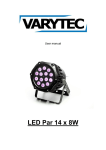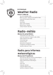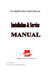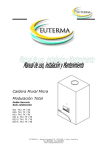
1
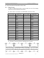
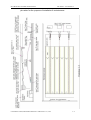
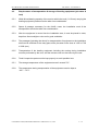
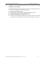
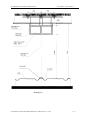
MC2 BOWLING SYSTEM USER MANUAL
SECTION 2 - Pre-Installation
SECTION 2
Pre-Installation
CONTENTS
2.1 Civil Construction & Decoration of the Center ----------------------------- 2 - 2
2.2 Power supply & Electrical Requirement -------------------------------------- 2 - 5
2.3 Lighting Requirement --------------------------------------------------------------- 2 - 8
2.4 Requirement of Civil Construction & Furnishing of
the bowling Center -------------------------------------------------------------------- 2 - 9
2.5 Requirement of Transportation & Storage of Bowling Equipment
(Pin-setter & Lanes) ----------------------------------------------------------------- 2 -10
2.6 Information to be Provided by Bowling Center before Installation
Of Bowling Equipment ------------------------------------------------------------- 2 -11
2.7 Others ------------------------------------------------------------------------------------ 2 -12
COPYRIGHT ©2004, SHANGHAI ZHONGLU INDUSTIAL CO., LTD
2-1
MC2 BOWLING SYSTEM USER MANUAL
SECTION 2 - Pre-Installation
2.1 Civil Construction & Decoration of the Center
2.1.1
Sizes of center
In order to enable the pin-setter to work normally, the size of the bowling
centermust meet the following requirements:
z
Size in width ( in accordance with ABC/WIBC standards of USA)
Qty. Of Lanes
Width (mm)
Qty. Of Lanes
Width (mm)
1
2
3
4
5
6
1867
3464
5261
6858
8655
10252
21
22
23
24
25
26
35807
37404
39201
40798
42595
44192
7
8
9
10
11
12
13
14
15
16
17
18
19
20
12049
13646
15443
17040
18837
20434
22231
23828
25625
27222
29019
30616
32413
34010
27
28
29
30
31
32
33
34
35
36
37
38
39
40
45989
47586
49383
50980
52777
54374
56171
57768
59565
61162
62959
64556
66353
67950
z
Drawing of Transverse Section of Bowling Lanes ( 4 lanes)
Drawing 2.1
COPYRIGHT ©2004, SHANGHAI ZHONGLU INDUSTIAL CO., LTD
2-2
MC2 BOWLING SYSTEM USER MANUAL
SECTION 2 - Pre-Installation
z Required Length & Height of Bowling Center ( e.g. 6 lanes)
COPYRIGHT ©2004, SHANGHAI ZHONGLU INDUSTIAL CO., LTD
2-3
MC2 BOWLING SYSTEM USER MANUAL
z
SECTION 2 - Pre-Installation
Passage: in-house passages (including the minimum 500mm wide maintenance path
beside lane)and, in-house service facilities (including pin-setter maintenance, customer
service facilities, etc) must be taken into consideration for overall arrangements by the
design & construction organization of the bowling Center.
2.1.2
The Water-Proof of the floor and the wall must be taken into
consideration during the design of the Center.
2.1.3
Safety passage must be taken into consideration during the design of the Center.
2.1.4
The side door to the pin-setter chamber must be at least 2200mm in width and
2400 mm in height so that there is sufficient room for moving the pin-setter and
the lane materials of 4500 mm long into the installation area.
2.1.5
The overall size of the pin-setter is 2850 mm in length, 1560 mm in Width and
1780 mm in height, it is 865 Kg in weight. The lane plate weighs 70 Kg/m2.
2.1.6
Effective acoustic materials must be used for the inside wall and the
ceiling of the pin-setter chamber .
2.1.7
Ventilation of the chamber must be taken into consideration.
2.1.8
Fire-proofing materials must be used for decoration.(Design &
installation must be in accordance with local safety regulations)
2.1.9
The pin-setter chamber must be equipped with fire extinguishers.
2.1.10
Air conditioning
z Room temperature of the bowling Center must be kept at 22°C-24°C, and the
relative humidity must be kept at 40% -50%.
z Room temperature of the pin-setter chamber must be kept at 22°C-28°C
z The heat generation of each pin-setter is 1000Kcal/H.
z Air-conditioning must be started 15 days prior to the installation of the lanes in
order to guarantee the quality of installation.
2.1.11
Wire pipes and other necessary pre-embedded parts must be embedded in
advance according to the electrical requirements.
2.1.12
Equipment (especially lane plates, lane wood, lane frame, etc) must be stored
in bowling Center of qualified conditions. They should stay there for 2 weeks
before being installed.
2.1.13
This equipment works under 1000 meters above sea level.
COPYRIGHT ©2004, SHANGHAI ZHONGLU INDUSTIAL CO., LTD
2-4
MC2 BOWLING SYSTEM USER MANUAL
SECTION 2 - Pre-Installation
2.2 Power supply & Electrical Requirement
2.2.1
The power distributor is shown in Drawing 2.3, the layout plan of
the operation desk and the seat system is shown in Drawing 2.4
2.2.2
Power supply of the equipment:
z
z
Capacity: single-phase 230V AC. 3Kw for each lane (excluding lighting and air
conditioning), voltage fluctuation not exceeding 10%. If these requirements can’t be
guaranteed, use a voltage regulator to guarantee the stability of the power supply.
Power supply to electrical equipment is in three-wire way, that is, two singlephase wires plus an additional protective earth wire.
2.2.3
Distribution of electrical sockets:
z
z
z
z
z
z
Electrical sockets for the pin-setter
One modulus switch box for every two lanes on the inner side of the
screen wall, with two low voltage & over voltage protection switches, 2
sockets of 230V/25A, 4 sockets of 230V/15A, all with grounding terminal.
Electrical sockets for ball-returning machine (every machine needs a
power of 550W)
Every group of lanes (two lanes) share one ball-returning machine (three
lanes need two machines. Note: usually lanes are in pairs, such as
2,4,6,etc. Special arrangements can be proposed by customers). One
socket of 230V/10A is installed at every ball-returning machine.
Electricity is supplied in single-phase three-wire method.
Voltage regulator socket at the operation table (every lane needs a
constant voltage power supply of 300W)
Power supply to the operation table must be voltage-regulated. Every
lane has one operation table. One socket of 230V/10A must be installed
in the 200 x 100 (mm) hole below the operation table, or the power wire
that is 1 meter out of the floor has a grounding.
Note: The earth wire here must be an independent grounding, separated
from the earth wire of the public power net.
Socket for the 29” monitor (each monitor needs a power of 150W)
Two 29” monitors are installed above the front side of the ball-returning
machine (one monitor for each lane). Above each holder of the monitor,
install a socket of 230V/5A.
Sockets for installation & maintenance
Install several sockets of 230V/15A on the walls or columns of the
bowling Center for the purpose of installation, maintenance & cleaning.
Sockets for pin-setter chamber
One socket of 230V/15A must be installed on the wall behind each set of
COPYRIGHT ©2004, SHANGHAI ZHONGLU INDUSTIAL CO., LTD
2-5
MC2 BOWLING SYSTEM USER MANUAL
SECTION 2 - Pre-Installation
pin-setter for the purpose of installation & maintenance.
COPYRIGHT ©2004, SHANGHAI ZHONGLU INDUSTIAL CO., LTD
2-6
MC2 BOWLING SYSTEM USER MANUAL
z
2.2.4
Sockets for front-desk:
Install several sockets of 230V/15A with earth wire at the front-desk.
Note: The grounding here must share the same grounding system of the
sockets for voltage regulator, and be separated from the public power net.
Layout of pre-embedded pipe
z
z
z
z
z
z
Two 2” PVC wire tubes must be placed on the ground of the gutter
between the pin-setter to the ball-returning machine (one for each lane)
Two 1-1/2 “PVC wire tubes must be placed between the main operation
tables and between the first main operation table and the front-desk (Note
1)
Two 1-1/2” PVC wire tubes must be placed between every main operation table
and the relevant secondary operation table. If the scoring system is Zhonglu
2000 serial, then one 1-1/2” PVC wire tube must be placed between every main
operation table and the front-desk. (Note 2)
One 2” PVC wire tube must be placed between the pin-setter and the 29”
monitor (one for every two lanes, going along the ceiling)
One 2” PVC wire tube must be placed from each side of the ball-returning
machine to the operation table (one for each lane). The tube at the operation
table must be 10mm-20mm above the floor (entering the table).
One 1-1/2” PVC tube must be pre-embedded from the main operation table to
the front-desk.
The tube of the main operation table side must be 10mm—20mm above the
floor (entering the operation table).
Remarks:
2.2.5
SECTION 2 - Pre-Installation
1) The PVC wire tubes shall be provided by the owner of
the bowling Center and will be used when installing the lane is. Each
lane is 40 meters long.
2) Main operation platform: when one scoring system controls 2 lanes
( as in QUBICA & Zhonglu 2000 serial), the left lane of the pair is the
main lane, the operation table here is the main one (computer is
installed inside this table), and the other is called the secondary
operation table; when one scoring system controls only one lane, the
relevant operation table is called the main operation table.
Requirements of grounding
The section area of the earth wire mustn’t be smaller than 4 mm2,
resistor mustn’t be over 4Ω.
COPYRIGHT ©2004, SHANGHAI ZHONGLU INDUSTIAL CO., LTD
the grounding
2-7
MC2 BOWLING SYSTEM USER MANUAL
SECTION 2 - Pre-Installation
2.3
LIGHTING REQUIREMENTS
2.3.1
The lighting brightness of the lane area must reach 300LUX – 350 LUX.
2.3.2
The lighting in the area of players and spectators must be 150LUX-200LUX
2.3.3
Two 40 W fluorescent lamps must be installed over the center line of every
two pin-setters in the pin-setter chamber.
2.1.4
The above-mentioned electrical devices must be taken into
consideration during the design, construction, installation & furnishing of the bowling
Center. They must be finished and supplied with power before the installation of
the bowling equipment and meet the above-mentioned requirements. All sockets
must be equipped with plugs. When pre-embedding the wire tubes, try to avoid
bending of the tube, and iron wires must be put inside the tubes for drawing wires.
COPYRIGHT ©2004, SHANGHAI ZHONGLU INDUSTIAL CO., LTD
2-8
MC2 BOWLING SYSTEM USER MANUAL
SECTION 2 - Pre-Installation
2.4.
REQUIREMENTS OF THE CIVIL CONSTRUCTION & FURNISHING OF THE
BOWLING CENTER
2.4.1
Because concrete nails are sometimes used during installation, the distance
between the water-proof layer and the surface of the concrete (the thickness of the
concrete layer) mustn’t be less than 60 mm in order to avoid any damage to the
water-proof layer. The flatness deviation of the concrete surface mustn’t be over
±6 mm. The grade number of the cement must be over No. 600, and the surface
of the concrete mustn’t be sandy.
2.4.2
Load bearing requirement of installation area:
z Pin-setter chamber (installing area of pin-setter) not less than 450 Kg/m2
z Lane area: not less than 300 Kg/m2
2.4.3
Installation of pin-setter & lanes must be started two weeks after the completion of
the civil construction & furnishing of the bowling Center.
2.4.4
Installation of monitor: hanging rails must be installed according to Drawing 2.2 &
Drawing 2.4 (sizes are only for reference, can differ according to different conditions
of different bowling Centers). The hanging rails must be able to bear the weight of
the monitor (60 Kg each), without any deformation or bending.
2.4.5
Installation of operation tables and seats must be started after finishing the
installation of the floor of the area of players and spectators.
2.4.6
The parquet of the seat area and the spectators’ area can be installed directly on the
concrete surface. Otherwise, use a middle layer of wood board between the
concrete surface and the parquet.
2.4.7
The power supply to the pin-setter, all kinds of sockets, pre-embedded wiring tubes
and in-house lighting must be finished to the requirements before the bowling
equipment is moved into the bowling Center for installation.
2.4.8
Except for the installation of the lane and the bowling equipment, all other works will
be designed and done by the owner of the bowling Center.
2.4.9
The installation requirements & the size of the multi-layer hanging screen are shown
in Drawing 2.6
COPYRIGHT ©2004, SHANGHAI ZHONGLU INDUSTIAL CO., LTD
2-9
MC2 BOWLING SYSTEM USER MANUAL
SECTION 2 - Pre-Installation
2.5
Requirements of transportation & storage of bowling equipment (pin-setter &
lane)
2.5.1
Width & load bearing capacity of the road on which the truck ( 8-15 tons) carrying the
bowling equipment passes must be taken into consideration
2.5.2
Space & passage necessary for the forklift, crane, the installation work & the
transportation should be taken into consideration.
2.5.3
After the equipment is moved into the installation area, it must be placed in order,
kept form direct sunlight or rain and in good ventilation.
2.5.4
The passages (including the doors) for transportation of equipment to the installation
site must be sufficient for the easy pass of the pin-setter in the sizes of 1350 x 1700
x 2000 (mm)
2.5.5
Transportation of the bowling equipment including the moving during installation
must be performed by the user, and the relevant cost is to be borne by the user.
2.5.6
Tools & expensive parts must be kept properly to avoid possible loss.
2.5.1
The storage temperature of the equipment mustn’t exceed 70℃.
2.5.8
The temperature during transportation of the equipment must be kept at
–25℃. - 55℃.
COPYRIGHT ©2004, SHANGHAI ZHONGLU INDUSTIAL CO., LTD
2 - 10
MC2 BOWLING SYSTEM USER MANUAL
2.6
SECTION 2 - Pre-Installation
Information to be provided by the owner of the bowling Center before
installation of the equipment
The following information must be provided by the owner of the bowling Center one
month prior to the installation of the bowling equipment:
z Layout plan of the bowling Center
z The plane figure & the side elevation drawing of the bowling Center
z Schedule of the in-house civil work and the furnishing
z Schedule of the installation of electrical devices
z The user must provide the plane figure of the bowling Center one and a half
months prior to the installation if the user has special requirement on the lanes.
COPYRIGHT ©2004, SHANGHAI ZHONGLU INDUSTIAL CO., LTD
2 - 11
MC2 BOWLING SYSTEM USER MANUAL
SECTION 2 - Pre-Installation
2.7
Others
2.7.1
The owner of the bowling Center is responsible for such safety measures as the
guard, the fire-protection, & the anti-burglary work
2.7.2
If wood lane is to be installed, one warehouse for dangerous goods (paint for the
lane) must be provided.
2.7.3
Arrange staff according to the contract.
2.7.4
The installation condition of the bowling Center must be in accordance with the local
requirements.
2.7.5
Before installation of the lanes, the maintenance people of the bowling Center must
be trained and be certified as qualified operator by our company.
2.7.6
Other work that requires co-operation
COPYRIGHT ©2004, SHANGHAI ZHONGLU INDUSTIAL CO., LTD
2 - 12
MC2 BOWLING SYSTEM USER MANUAL
SECTION 2 - Pre-Installation
Drawing 2.4
COPYRIGHT ©2004, SHANGHAI ZHONGLU INDUSTIAL CO., LTD
2 - 13
MC2 BOWLING SYSTEM USER MANUAL
ZL2000-Z2
SECTION 2 - Pre-Installation
Seat System Layout
Drawing 2.5.1
COPYRIGHT ©2004, SHANGHAI ZHONGLU INDUSTIAL CO., LTD
2 - 14
MC2 BOWLING SYSTEM USER MANUAL
SECTION 2 - Pre-Installation
ZL2000-Z3 Seat System Layout
Drawing 2.5.2
COPYRIGHT ©2004, SHANGHAI ZHONGLU INDUSTIAL CO., LTD
2 - 15
MC2 BOWLING SYSTEM USER MANUAL
SECTION 2 - Pre-Installation
ZL2000-Z4 Seat System Layout
Drawing 2.5.3
COPYRIGHT ©2004, SHANGHAI ZHONGLU INDUSTIAL CO., LTD
2 - 16
MC2 BOWLING SYSTEM USER MANUAL
SECTION 2 - Pre-Installation
VIA EVOLUTION ON-LANE SEATING SYSTEM
Drawing 2.5.4
COPYRIGHT ©2004, SHANGHAI ZHONGLU INDUSTIAL CO., LTD
2 - 17
MC2 BOWLING SYSTEM USER MANUAL
SECTION 2 - Pre-Installation
Multi-layer MASKING
Drawing 2.6
COPYRIGHT ©2004, SHANGHAI ZHONGLU INDUSTIAL CO., LTD
2 - 18