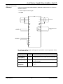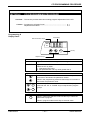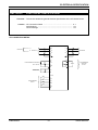
1
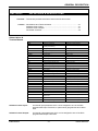
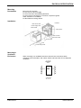
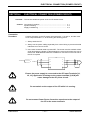
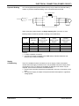
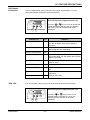
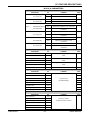
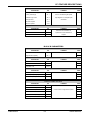
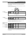
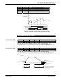
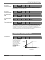
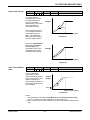
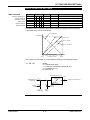
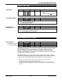
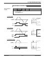
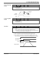
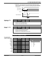
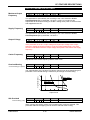
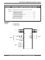
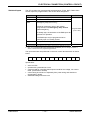
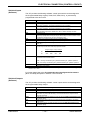
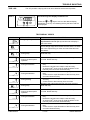
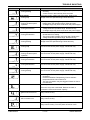
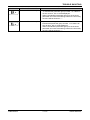
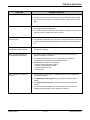
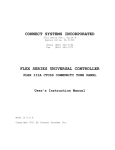
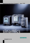
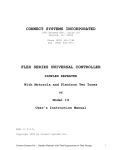
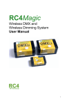
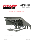
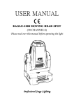
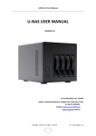
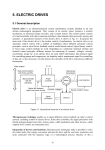
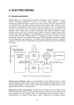
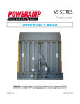
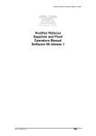
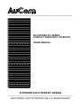
_________________________________________________________ AUCOSPEED CFI SERIES COMPACT FREQUENCY INVERTER USERS MANUAL SUPERIOR SOLUTIONS BY DESIGN __________________________________________________________________ ELECTRONIC SOFT STARTERS AND A.C.SPEED DRIVES WARNING ELECTRICAL SHOCK HAZARD ENSURE THE DSC IS COMPLETELY ISOLATED FROM THE POWER SUPPLY BEFORE ATTEMPTING ANY WORK ON THE UNIT _______________________________________________________________________ CFI USERS MANUAL THIS USERS MANUAL COVERS ALL CFI MODELS To ensure trouble free installation and commissioning it is strongly recommended that users and installers read this Users Manual completely prior to installation and commissioning. SECTION 1 CAUTION STATEMENTS Details Possible Causes Of Equipment Damage - Caution Statements SECTION 2 DEFINITIONS & DESCRIPTIONS Alphabetical Listing Of Terms Used In This Manual Abbreviations and Terminal Names Software Control Input Software Control Output Parameter Overview SECTION 3 PHYSICAL SPECIFICATION How To Physically Install The CFI - Dimensions - Weights - Mounting Precautions - Installation - Mounting In Ventilated Enclosures SECTION 4 ELECTRICAL CONNECTION (POWER CIRCUIT) How To Make Electrical Connections To And From The CFI - Connection Procedure - Dynamic Braking - Supply Conditioning SECTION 5 COMMISSIONING PROCEDURE How To Commission The CFI - Overview - Step By Step Procedure SECTION 6 CFI FEATURE DESCRIPTIONS Comprehensive Description Of Features Provided By The CFI - Overview - LED Display Parameters - Trip Log - Parameter Listing - Protection Descriptions CFI SERIES -- i -- AMV00059 REV 1.4 _______________________________________________________________________ SECTION 7 ELECTRICAL CONNECTION (CONTROL CIRCUIT) How To Connect Control Circuitry To The CFI - Input/Output Terminals Overview - Switched Input Terminals - Switched Output Terminals - Analogue Output Terminals - Software Control Input/Output Overview - Switched Inputs (Software) - Switched Outputs (Software) - Typical Connection Drawing 1 - Typical Connection Drawing 2 - Typical Connection Drawing 3 SECTION 8 CFI PROGRAMMING PROCEDURE How To Program The CFI - Programming and Display Panel - Adjustment Procedure SECTION 9 ELECTRICAL SPECIFICATION Details Electrical Specification Of The CFI - CFI Connection Detail - General Specification - Current Ratings SECTION 10 TROUBLE SHOOTING GUIDE Step by Step guide CFI SERIES -- ii -- AMV00059 REV 1.4 CAUTION STATEMENTS SECTION 1 CAUTION STATEMENTS Overview : This section highlights potential causes of equipment damage Content : CAUTION Caution List ......................................................................... 1-1 This caution symbol is used throughout the CFI Manual to draw special attention to activities which may result in equipment damage. A summary of these cautions is listed below. Such Caution Statements cannot cover every potential cause of equipment damage but can highlight common causes of damage. It is therefore the installers responsibility to adhere to all instructions in this manual, to follow good electrical practice and to seek advice before operating this equipment in a manner other than as detailed in this manual. Ensure that the CFI is completely isolated from the power supply before attempting any work on the unit. Entry of metal swarf into the cabinet can cause equipment failure. Ensure the power supply is connect to the CFI Input Terminals [L1, L2, L3]. Application of voltage to the output terminals [U,V,W] will cause damage to the CFI power circuit. Ensure the CFI is properly earthed. Ensure the CFI has adequate ventilation Observe the CFI specifications The CFI DC Bus remains charged even if the power is off. Wait at least 10 minutes after removal of power before servicing the equipment. Do not switch on the output of the CFI while it is running. At low speeds motor cooling is severely restricted and motor overheating can occur at moderate loading. Thermistor protection should be used for motors which will operate at for extended period at a reduced speed while under load. Do not connect Power Factor Correction capacitors to the output of the CFI or the motor terminals. The examples and diagrams in this manual are included solely for illustrative purposes. Users are cautioned that the information contained in this manual is subject to change at any time and without prior notice. In no event will responsibility or liability be accepted for direct or indirect or consequential damages resulting from the use or application of this equipment. CFI SERIES 1-1 USERS MANUAL CAUTION STATEMENTS CFI SERIES 1-2 USERS MANUAL GENERAL DESCRIPTION SECTION 2 DEFINITIONS & DESCRIPTIONS Overview : This section provides overview of terms used in this manual. Content : Abreviations and Terminal Names ....................................................... Software Control Input ........................................................................ Software Control Output ..................................................................... Parameter Overview ............................................................................. 2-1 2-1 2-1 2-2 Abbreviations & Terminal Names SYMBOL DESCRIPTION TYPE ATN Frequency Attained Software Control Output C SEL Ramp Selection (Primary/Secondary) Software Control Input COM Analogue Input Terminal Common Analogue Input EMS Emergency Stop Relay Input F.JOG Forward Inching Software Control Input F.RUN Forward Run Relay Input FC,FA,FB Relay Outputs Relay Output FDW Frequency Down Software Control Input FLT Trip (Fault) Software Control Output FSI 4-20mA Speed Signal Input Analogue Input Ftrq Supply Frequency FSV 0-10VDC Speed Signal Input FUP Frequency Up Software Control Input HOLD Hold (Latch) Software Control Input I DET Current Set Point [B26-1] Reached Software Control Output IFS Use IFS Speed Signal Software Control Input MC Precharging In Progress Software Control Output P10 10V Source For FSV Analogue Output PROG Activate Multi-Step Function Software Control Input PSI1 Programmable Input 1 Relay Input R.JOG Reverse Inching Software Control Input R.RUN Reverse Run Software Control Input RDY Ready Software Control Output REV Reverse Software Control Output RST Fault Reset Relay Input RUN Run Software Control Output S0, S1 Selector Switches For Multi-Step & Pattern Run Software Control Input SPD Speed Set Points Reached Software Control Output VFS Use FSV Speed Signal Software Control Input Analogue Input Software Control Input : An internal input parameter which can be assigned to one of the DSC programmable Input Terminals, or permanently programmed to be ON or OFF. Software Control Output : An internal output parameter which can be assigned to one of the DSC programmable Output Terminals. CFI SERIES 2-1 USERS MANUAL GENERAL DESCRIPTION Parameter Overview LED Display Parameters M0. Output Frequency M1. Set Frequency M2. Output Current in Amps M3. Output Current in % M4. Overload Monitor M5. D.C.Bus Voltage M6. Output Voltage Trip Log F0. F1. Most Recent Fault Previous Fault BLOCK A PARAMETERS Frequency Settings A0.0 Run Speed Standard Adjustment A0.1 Fine Adjustment A0.2 Jog Speed Standard Adjustment A0.3 Fine Adjustment A0.4 Multi-Speed Step 0 Standard Adjustment A0.5 Fine Adjustment A0.6 Multi-Speed Step 1 Standard Adjustment A0.7 Fine Adjustment A0.8 Multi-Speed Step 2 Standard Adjustment A0.9 Fine Adjustment A0.A Multi-Speed Step 3 Standard Adjustment A0.b Fine Adjustment Acceleration/Deceleration Settings A1.0 Acceleration Rate (seconds) A1.1 Deceleration Rate (seconds) A1.2 Secondary Acceleration Rate A1.3 Secondary Deceleration Rate A1.4 Jog Acceleration Rate A1.5 Jog Deceleration Rate A1.6 Time Unit Multiplier Torque Boost & DC Brake Settings A2-0 Torque Boost (%) A2-1 Square-law Torque A2-2 Auto Torque Boost Gain A2-3 Slip Compensation Gain (%) A2-4 DC Brake Voltage A2-5 DC Brake Time A2-6 Start Frequency A2-7 Stop Frequency Skip Frequency Settings A3-0 Skip Frequency 1 A3-1 Skip Band 1 A3-2 Skip Frequency 2 A3-3 Skip Band 2 A3-4 Skip Frequency 3 A3-5 Skip Band 3 Ratio Interlock Settings A4-0 Polarity Of Coefficient (A) A4-1 Polarity Of Bias (B) A4-2 Coefficient (A) Value A4-3 Bias (B) Value A4-4 Maximum Speed A4-5 Minimum Speed Speed/Current Output Signal Settings A5-0 ATN Detect Band A5-1 IDET Current Detect Level A5-2 SPD Speed Detect Level CFI SERIES BLOCK B PARAMETERS Overcurrent Limit Settings B3.0 Drive Current Limit B3.1 Regenerative Capacity Sundry Settings B4.0 Fault Reset B4.1 Load Default Values B4.2 Parameter Lock Start Interlock Settings B5.0 Start/Stop Frequencies B5.1 Start/Stop Frequency Hysterises B5.2 Interlock Frequency Control Format Settings B6.0 Run Command Format B6.1 F RUN, R RUN Stop Format B6.2 F JOG, R JOG Stop Format B6.3 Autostart B6.4 EMS Command Input Logic B6.5 EMS Stop Format Programmable Input Settings - 1 B7.0 F RUN B7.1 R RUN B7.2 F JOG B7.3 R JOG B7.4 EMS B7.5 RESET B7.6 HOLD B7.7 CSEL Programmable Input Settings - 2 B8.0 VFS B8.1 IFS B8.2 PROG B8.3 S0 B8.4 S1 B8.5 FUP B8.6 FDW B8.7 FUP/FDW Step B8.8 Relay Output Parameter Assign. B8.9 LED Display Initialisation Output Parameter Settings B9.0 Maximum Output Frequency Fmax B9.1 Supply Frequency Ftrq B9.2 Output Voltage B9.3 Carrier Frequency B9.4 Overload Setting B9.5 0Hz Overload B9.6 Input Voltage B9.7 Preset Fmax/Ftrq Pattern 2-2 USERS MANUAL PHYSICAL SPECIFICATION SECTION 3 PHYSICAL SPECIFICATION Overview : This section details mounting instructions for the CFI Series Drives. Content : Dimensions ............................................................................... Weights ..................................................................................... Mounting Precautions ............................................................... Installation ................................................................................. Ventilation : Mounting In Ventilated Enclosures ........................ 3-1 3-1 3-2 3-2 3-2 Dimensions (mm) W0 D W1 Ød H2 RUN FLT SET H1 H0 H3 MODEL CFI-2030 CFI-2042 CFI-2080 CFI-2011 CFI-0025 CFI-0036 CFI-0055 CFI SERIES Wo 105 W1 90 Ho 150 H1 134 H2 8 H3 8 D 130 Ød 4.8 Weight kg 1.2 135 118 200 150 9 41 167 5.8 2.4 -- 3-1 -- USERS MANUAL PHYSICAL SPECIFICATION Mounting Precautions Mount the CFI vertically Do not mount in direct sunlight Do not locate near heat radiating elements Do not locate in area subject to corrosive or explosive gases Allow clearance for ventilation Do Not Obstruct Cooling Airflow Installation Heatsink Main Circuit PCB Power Supply PCB Control PCB Fixing Screw Power Terminal Wire Lead In Slot Control Terminal Cover Cover Fixing Screw Mounting In Ventilated Enclosures When mounting in a ventilated enclosure ensure there is at least a 50mm clearance around the sides, and 150mm above and below the CFI for adequate ventilation. 150mm 50mm CFI 50mm 150mm CFI SERIES -- 3-2 -- USERS MANUAL ELECTRICAL CONNECTION (POWER CIRCUIT) SECTION 4 ELECTRICAL CONNECTION (POWER CIRCUIT) Overview : This section details the power circuit for CFI Series Drives. Content Connection Procedure Connection Procedure .............................................................. 4-1 Dynamic Braking ....................................................................... 4-2 Supply Conditioning .................................................................. 4-2 Connect the supply to the CFI power input terminals L1, L2 and L3, and the motor to CFI output terminals U, V, W observing the following points : 1. Always earth the CFI 2. Always run the power cabling separately from control wiring to prevent electrical interference on control circuits. 3. Use neutral screened cable to prevent RFI. The screen must be earthed at both ends. Minimising the length of cable between the motor and inverter also acts to reduce RFI. Dedicated RFI filters are available for connection on the line side of the CFI if required. CFI L1 L1 U L2 V L3 W 1Ø SUPPLY N CAUTION 3 SUPPLY M Ensure the power supply is connected to the CFI Input Terminals [L1, L2, L3]. Application of voltage to the output terminals [U,V,W] will cause damage to the CFI power circuit. Do not switch on the output of the CFI while it is running. CAUTION Do not connect Power Factor Correction capacitors to the output of the CFI or the motor terminals. CAUTION CFI SERIES -- 4-1-- USERS MANUAL ELECTRICAL CONNECTION (POWER CIRCUIT) Dynamic Braking CFI units supplied with Dynamic Brake circuitry may be fitted an external braking resistor to provide increased braking of the connected motor and load. Dynamic Braking Resistor L1 L1 L+ B U 1Ø SUPPLY N 3 SUPPLY L2 V L3 W M When using the dynamic Brake, set Regen Capacity [B3-1] for 30% or more. Braking resistor should be selected according to the table below. Model Minimum Resistance Value (Ω) CFI-2080 CFI-2110 CFI-0025 CFI-0036 CFI-0055 80 50 200 200 200 100% torque 10%ED (60Sec/10min) Register 400W 100Ω 1P 300W 150Ω 2P 300W 680Ω 1P 300W 680Ω 2P 300W 470Ω 2P 100% torque 5%ED (30Sec/10min) Register 300W 100Ω 1P 300W 150Ω 2P 200W 680Ω 1P 200W 680Ω 2P 300W 470Ω 2P 100% torque 2.5%ED (15Sec/10min) Register 300W 100Ω 1P 300W 68Ω 1P 200W 680Ω 1P 300W 330Ω 1P 200W 470Ω 2P NOTES 1. P refers to parallel connection. 2. A maximum of 800V is applied to the DBR resistor. Resistor selection and wiring must be rated accordingly. Supply Conditioning CFI SERIES The CFI is suitable for direct connection to an AC supply. There are however certain abnormal supply conditions which can potentially cause drive input power componentry to fail. To reduce the possibility of damage a line reactor may be required. A line reactor should be considered where : 1. Power Factor correction capacitors are switched in and out on the supply to the drive. 2. The electrical supply is subject to frequent transient interruptions or significant voltage spikes. -- 4-2-- USERS MANUAL COMMISSIONING PROCEDURE SECTION 5 COMMISSIONING PROCEDURE Overview : This section details commissioning procedures for a CFI installation. Content : Overview ................................................................................... 5-1 Step By Step Guide ................................................................... 5-2 Overview This section provides a step by step guide to commissioning the CFI in local control mode. Having complete commissioning to this stage, users wishing to utilise any of the CFI’s other control options or advanced features, can then refer to appropriate sections in this manual. The basic steps followed in the commissioning procedure are : Connect the Motor and Supply To the CFI, and Then Apply Power Ø Make/Verify Essential Parameter Adjustments Ø Start CFI and Prove Basic Operation In Local Mode Ø Adjust Performance Related Parameters Ø Adjust Parameters For Desired External Control Format Ø Start CFI and Prove Operation With Desired Control Configuration CFI SERIES -- 5-1-- USERS MANUAL COMMISSIONING PROCEDURE STEP 1 POWER UP THE CFI [Refer Section 4 For Electrical Connection Detail] 1. Connect the motor and supply to the CFI, and apply power to the CFI. The CFI will perform its power up checks and, when finished, the LED display will and the ‘LCL’ and Hz LEDs will illuminate. show RUN FLT STEP 2 MAKE/VERIFY ESSENTIAL PARAMETER ADJUSTMENTS [Refer Section 8 For Programming Procedures] 1. Verify Supply Voltage [B9-6] and Supply Frequency [B9-1] are set correctly for the connected supply. STEP 3 START THE CFI AND PROVE BASIC OPERATION [Refer Section 7 For Detail Of CFI Control Inputs] FORWARD RUN CFI Output Frequency F-RUN REVERSE RUN PSI1 (R RUN) ([B7-1]=4) RYO F.Run R.Run 1. With power applied to the CFI, turn ON the F.RUN control input. to display output frequency. The display The LED display will change from will increase to . This is because the local Run Speed [A0-0] is set to 10Hz as the default. Check that : 1. The motor runs smoothly 2. The motor runs in the correct direction 2. Turn OFF the F.RUN control input and stop the motor. 3. Turn ON the PSI1 (R.RUN) control input. The motor should run at 10Hz in reverse. 4. Turn OFF the R.RUN control input and stop the motor. 5. Turn ON the F.RUN control input. The motor should again run at 10Hz in the forward direction. 6. Adjust motor speed to 50Hz Select Parameter Run Speed [A0-0] using the key and then adjust motor speed using the 7. and keys. Press the SET keys. Turn OFF the F.RUN control input when the speed reaches 50Hz The LED Display will show DC Brake. CFI SERIES and at the end of the stop, indicating operation of the -- 5-2-- USERS MANUAL COMMISSIONING PROCEDURE STEP 4 ADJUST PERFORMANCE RELATED PARAMETERS [Refer Section 6 For Parameter/Function Detail] The CFI offers an extensive function set to cater for a variety of application types. These features do not need to be set unless required. Adjustment of the most commonly used features is detailed below. 1. Adjust the Acceleration Rate [A1-0] to suit the load. 2. Adjust the Deceleration rate [A1-1] to suit the load. 3. The default maximum speed is set at 50Hz. If not appropriate adjust the Maximum Frequency Setting [B9-0]. Note that the Maximum Frequency setting defaults to 50Hz each time the CFI is powered up unless this feature is over-ridden using the Supply Voltage/Frequency Setting [B9-7]. 4. STEP 5 To utilise any other the CFI’s other features refer to section 3 of this manual for features descriptions and adjustment detail. ADJUST PARAMETERS FOR DESIRED EXTERNAL CONTROL FORMAT [Refer Section 7 For CFI Control Options] The CFI can be configured for a wide range of control formats. Section 7 of this manual details the options available. STEP 6 RUN THE CFI AND PROVE OPERATION OF CONTROL CIRCUIT Once the desired external control circuitry has been connected test its operation. CFI SERIES -- 5-3-- USERS MANUAL COMMISSIONING PROCEDURE CFI SERIES -- 5-4-- USERS MANUAL CFI FEATURE DESCRIPTIONS SECTION 6 CFI FEATURE DESCRIPTIONS Overview : This section describes the purpose and operation of each feature of the CFI Series Drives. Content : Overview ............................................................................. LED Display Parameters ..................................................... Trip Log ............................................................................... Parameter Listing ................................................................ Parameter Descriptions ...................................................... Overview 6-1 6-2 6-2 6-3 6-6 CFI features are grouped into four blocks as detailed below. LED DISPLAY PARAMETERS • • • • Frequency displays Current displays Overload display Voltage displays TRIP LOG • Last Fault • Previous Fault BLOCK A • • • • • • Frequently Adjusted Settings Frequency Settings Acceleration/Deceleration Settings Torque Boost & DC Brake Settings Skip Frequency Settings Ratio Interlock Settings Speed Current Output Signal Settings BLOCK B • • • • • • CFI SERIES Infrequently Adjusted Settings Overcurrent Limit Settings Sundry Settings Start Interlock Settings Control Format Settings Programmable Input Settings Output Parameters Settings 6-1 USERS MANUAL CFI FEATURE DESCRIPTIONS LED Display Parameters The CFI digital display can be used to view a variety of parameters. To scroll through the Display Parameter list do the following : Scroll through the Display Parameter List. RUN FLT ** PARAMETER TRIP LOG or keys to move to the desired Press the display parameter (M0 thru M6). On releasing the key the value of the parameter will be displayed. SET NO COMMENT Output Frequency (Hz) M0 “OFF” will display when the CFI output is shut off. “Br” will display when the DC Brake is operating. Set Frequency (Hz) M1 The frequency command currently being followed by the CFI is displayed. Output Current (Amps) M2 Output Current (%) M3 Output current is displayed as a percentage of CFI output rating. “Br” will display when the DC Brake is operating. Overload Monitor (%) M4 An overload trip occurs when this value reaches 100% DC Bus Voltage (V) M5 Output Voltage (V) M6 “OFF” will display when the CFI output is shut off. Latest Fault F0 Refer to the Trouble Shooting Section of this manual for Previous Fault F1 detail of fault codes. The CFI provides a trip log which can show detail of the last two trip states : Scroll through the Display Parameter List. RUN FLT ** CFI SERIES or keys to move to the Press the desired display parameter (F1 & F2). On releasing the key the fault code will be displayed SET 6-2 USERS MANUAL CFI FEATURE DESCRIPTIONS BLOCK A PARAMETERS FREQUENCY SETTINGS PARAMETER Run Speed Jog Speed NO COMMENT Standard Adjustment A0-0 Adjusts Run Speed In 1Hz Increments PAGE Fine Adjustment A0-1 Adjusts Run Speed In 0.01Hz Increments Standard Adjustment A0-2 Adjusts Jog Speed In 1Hz Increments Fine Adjustment A0-3 Adjusts Jog Speed In 0.01Hz Increments Standard Adjustment A0-4 Adjusts Step 0 Speed In 1Hz Increments Fine Adjustment A0-5 Adjusts Step 0 Speed In 0.01Hz Increments Standard Adjustment A0-6 Adjusts Step 1 Speed In 1Hz Increments Fine Adjustment A0-7 Adjusts Step 1 Speed In 0.01Hz Increments Standard Adjustment A0-8 Adjusts Step 2 Speed In 1Hz Increments Fine Adjustment A0-9 Adjusts Step 2 Speed In 0.01Hz Increments Standard Adjustment A0-A Adjusts Step 3 Speed In 1Hz Increments Fine Adjustment A0-b Adjusts Step 3 Speed In 0.01Hz Increments Multi-Step Frequency Settings Step 0 Step 1 Step 2 Step 3 ACCELERATION/DECELERATION SETTINGS NO COMMENT Acceleration Rate (seconds) PARAMETER A1-0 Primary Acceleration & Deceleration PAGE Deceleration Rate (seconds) A1-1 Rates Secondary Acceleration Rate A1-2 Alternate Acceleration & Deceleration Secondary Deceleration Rate A1-3 Rates Jog Acceleration Rate A1-4 Jog Acceleration & Deceleration Jog Deceleration Rate A1-5 Rates Time Unit Multiplier A1-6 TORQUE BOOST & DC BRAKE SETTINGS PARAMETER NO COMMENT Torque Boost (%) A2-0 Square-law Torque A2-1 Auto Torque Boost Gain A2-2 Torque Boost & Slip Compensation Gain (%) A2-3 DC Brake Settings DC Brake Voltage A2-4 DC Brake Time A2-5 Start Frequency A2-6 Stop Frequency A2-7 PAGE SKIP FREQUENCY SETTINGS PARAMETER CFI SERIES NO COMMENT PAGE Skip Frequency 1 A3-0 Skip Band 1 A3-1 Frequency Settings Skip Frequency 2 A3-2 For Skip Frequency Function Skip Band 2 A3-3 Skip Frequency 3 A3-4 Skip Band 3 A3-5 6-3 USERS MANUAL CFI FEATURE DESCRIPTIONS RATIO INTERLOCK SETTINGS PARAMETER NO COMMENT PAGE Polarity Of Coefficient (A) A4-0 Polarity Of Bias (B) A4-1 Use For Conditioning Of Speed Coefficient (A) Value A4-2 Input Signals. For example Span Bias (B) Value A4-3 and Offset. Maximum Speed A4-4 Minimum Speed A4-5 SPEED/CURRENT OUTPUT SIGNAL SETTINGS PARAMETER NO COMMENT PAGE ATN Detect Band A5-0 Set Points For Activation Of IDET Current Detect Level A5-1 Speed and Current Reference SPD Speed Detect Level A5-2 Outputs BLOCK B PARAMETERS OVERCURRENT LIMIT SETTINGS PARAMETER NO Drive Current Limit B3-0 Regenerative Capacity B3-1 COMMENT PAGE COMMENT PAGE SUNDRY SETTINGS PARAMETER NO Fault Reset B4-0 Load Default Values B4-1 Parameter Lock B4-2 START INTERLOCK SETTINGS PARAMETER NO Start/Stop Frequencies B5-0 Start/Stop Frequency Hysterises B5-1 Interlock Frequency B5-2 COMMENT PAGE CONTROL FORMAT SETTINGS PARAMETER CFI SERIES NO Run Command Format B6-0 F RUN, R RUN Stop Format B6-1 F JOG, R JOG Stop Format B6-2 Autostart B6-3 EMS Command Input Logic B6-4 EMS Stop Format B6-5 6-4 COMMENT PAGE Control Circuit Configuration Options USERS MANUAL CFI FEATURE DESCRIPTIONS PROGRAMMABLE INPUT SETTINGS - 1 PARAMETER NO F RUN B7-0 R RUN B7-1 F JOG B7-2 R JOG B7-3 EMS B7-4 RESET B7-5 HOLD B7-6 CSEL B7-7 COMMENT PAGE Programable Input Assignment PROGRAMMABLE INPUT SETTINGS - 2 PARAMETER NO VFS B8-0 IFS B8-1 PROG B8-2 S0 B8-3 S1 B8-4 FUP B8-5 FDW B8-6 FUP/FDW Step B8-7 Relay Output Parameter Assign. B8-8 LED Display Initialisation B8-9 COMMENT PAGE Programable Input Assignment Programable Output Assignment OUTPUT PARAMETER SETTINGS PARAMETER CFI SERIES NO Maximum Output Frequency Fmax B9-0 Supply Frequency Ftrq B9-1 Output Voltage B9-2 Carrier Frequency B9-3 Overload Setting B9-4 0Hz Overload B9-5 Input Voltage B9-6 Preset Fmax/Ftrq Pattern B9-7 6-5 COMMENT PAGE Motor Overload Adjustment USERS MANUAL CFI FEATURE DESCRIPTIONS FREQUENCY SETTINGS Each CFI frequency setting parameter is shown in two parts. The first allows the setting to be made in 1.0Hz increments. The second allows fine adjustment in 0.01Hz increments. for example : Run Speed can be set in 1Hz steps using parameter A0-0, while finer adjustments would be made using A0-1. A0-0 Display Run Speed Standard Adjustment Fine Adjustment A0-1 Display NUMBER DEFAULT MIN MAX A0-0 A0-1 1 0. 0 0 0.10 Fmax UNIT Hz Maximum Frequency as set by the in parameter B9-0 Jog Speed Standard Adjustment Fine Adjustment NUMBER A0-2 A0-3 DEFAULT 5. 0 0 MIN MAX 0.10 Fmax UNIT Hz Sets motor speed when in jog mode. Dedicated jog acceleration and deceleration times can be set using the Jog Acceleration and Jog Deceleration functions [A1-4 and A1-5.] Multi-Step Frequency Settings Step 0 Standard Adjustment Fine Adjustment Step 1 Standard Adjustment Fine Adjustment Step 2 Standard Adjustment Fine Adjustment Step 3 Standard Adjustment Fine Adjustment NUMBER A0-4 A0-5 A0-6 A0-7 A0-8 A0-9 A0-A A0-b DEFAULT MIN MAX 1 0. 0 0.10 Fmax UNIT Hz 1 0. 0 0.10 Fmax Hz 1 0. 0 0.10 Fmax Hz 1 0. 0 0.10 Fmax Hz These parameters specify the frequency set points for the Multi-Step Function. The Multi-Step function is activated by setting the PROG software control input [B8-2] to ON. The programmed frequency settings are selected using the S0 & S1 inputs as detailed below. CFI SERIES 6-6 USERS MANUAL CFI FEATURE DESCRIPTIONS S0 OFF OFF ON ON S1 OFF ON OFF ON Selected Parameter A0-4: Program Frequency - 0 A0-6: Program Frequency -1 A0-8: Program Frequency -2 A0-A: Program Frequency -3 OUTPUT FREQUENCY [A0-A] [A0-8] [A0-0] [A0-0] [A0-6] [A0-4] PROG [B8-2] S0 [B8-3] S1 [B8-4] NOTE : F.RUN is ON, VFS and IFS are OFF ACCELERATION SETTINGS Acceleration Rate NUMBER DEFAULT A1-0 1 0. 0 MIN MAX UNIT 0.1 99.9 Sec Sets the rate of motor acceleration when the motor increases speed. The acceleration time can be further extended using the Time Unit Multiplier [A1-6]. Deceleration Rate NUMBER DEFAULT A1-1 2 0. 0 MIN MAX UNIT 0.1 99.9 Sec Sets the rate of motor deceleration when the motor decreases speed. The deceleration time can be further extended using the Time Unit Multiplier [A16]. Frequency [A2-5] [A2-4] Stop Frequency Start Frequency [A2-2] DC Braking Voltage [A2-3] DC Braking Time CFI SERIES [A1-0] Acceleration Time [A1-1] Deceleration Time [A1-2] Secondary Acceleration Time [A1-3] Secondary Deceleration Time 6-7 Note: Secondary Acceleration Rates are selected by turning on the CEL software control input. USERS MANUAL CFI FEATURE DESCRIPTIONS Secondary Acceleration Rate NUMBER A1-2 DEFAULT 1 0. 0 MIN MAX UNIT 0.1 99.9 Seconds The secondary Acceleration and Deceleration Rates are activated by turning the CSEL Software Control Input [B7-7] ON. Secondary Deceleration Rate NUMBER Jog Acceleration Rate NUMBER Jog Deceleration Rate NUMBER Time Unit Multiplier NUMBER A1-3 A1-4 A1-5 DEFAULT 2 0. 0 DEFAULT 5. 0 DEFAULT 5. 0 DEFAULT A1-6 MIN MAX UNIT 0.1 99.9 Seconds MIN MAX UNIT 0.1 99.9 Seconds MIN MAX UNIT 0.1 99.9 Seconds MIN MAX UNIT 1 100 1 Acceleration and deceleration time settings can be modified by setting the Time Unit multiplier to a value greater than one. This setting affects all acceleration and deceleration time parameters. Acceleration and Deceleration settings can be increased to a maximum of 3600 seconds. Multiplication’s exceeding 3600seconds will be automatically result in the maximum 3600 second setting. TORQUE BOOST & D.C.BRAKE SETTINGS Torque Boost NUMBER A2-0 DEFAULT 3. 0 MIN MAX 0.0 25 UNIT % This figure sets the level of torque boost at 0Hz. If the motor does not achieve breakaway torque slowly increase the value of this parameter until breakaway torque is achieved. Voltage [A2-0] Supply Frequency [B9-1] Frequency CFI SERIES 6-8 USERS MANUAL CFI FEATURE DESCRIPTIONS Square-law Torque NUMBER A2-1 DEFAULT 0. 0 This figure sets the voltage/frequency ratio for loads that follow a Square-Law torque characteristic. Use of this feature will result in increased efficiency. MIN MAX 0.0 25 Voltage [A2-1] The parameter sets the % of voltage reduction at half supply frequency. [B9-1 / 2]. Adjustment levels are determined by the load characteristics. If both the Torque Boost [A2-0] and the SquareLaw Torque [A2-1] parameters are set, the voltage/frequency ratio will reflect both settings. UNIT % Supply Frequency [B9-1] Frequency Voltage Supply Frequency [B9-1] Frequency Auto Torque Boost Gain NUMBER A2-2 DEFAULT 0. 0 Auto Torque Boost dynamically controls output voltage dependent upon motor loading. Thus optimum efficiency is automatically maintained at all times irrespective of motor loading. MIN MAX 0.0 20 UNIT % Output Voltage [A2-6] Supply Frequency [B9-1] Frequency Notes : 1. This parameter over-rides Torque Boost [A2-0] and Square-Law Torque [A2-1]. To defeat Auto-Torque Boost set to zero ([A2-6] = 0). 2. Motor rotation may become unstable or the drive may trip if the setting is too high. CFI SERIES 6-9 USERS MANUAL CFI FEATURE DESCRIPTIONS Slip Compensation NUMBER A2-3 DEFAULT 0. 0 0 MIN MAX UNIT 0.00 20.0 % This parameter allows compensation for motor slip [%] at full load. Output Frequency Output frequency is controlled according to motor load torque as shown in the graph. Load Torque Motor rotation may become unstable if the setting is too high. The maximum setting should be no greater than the motors % slip at full load. DC Brake Voltage NUMBER DEFAULT MIN MAX A2-4 5. 0 0.0 20.0 The default setting is model dependent. DC Brake Time NUMBER A2-5 DEFAULT 2. 0 UNIT % MIN MAX UNIT 0.0 20.0 Seconds The DC Brake allows the motor and load to be stopped more rapidly than with the coast to stop method. Alter the DC Brake in units of 1% or less at a time while monitoring the output current to ensure it does not exceed drive ratings. The D.C.Brake does not energise until the stop frequency is reached. [A2-7] [A2-6] Stop Frequency Start Frequency [A2-4] DC Braking Voltage [A2-5] DC Braking Time [A1-0] Acceleration Time Start Frequency NUMBER A2-6 DEFAULT 1. 0 [A1-1] Deceleration Time MIN MAX UNIT 0.1 60.0 Hz Should a load not breakaway until the output frequency has increase to a level above 1Hz, this feature can be used to step to the required frequency straight away thus avoiding unnecessary motor heating. This setting should be made in 1Hz increments and set to the minimum possible level. CFI SERIES 6-10 USERS MANUAL CFI FEATURE DESCRIPTIONS Stop Frequency NUMBER A2-7 DEFAULT 1. 0 MIN MAX UNIT 0.1 60.0 Hz [A2-7] [A2-6] Stop Frequency Start Frequency [A2-4] DC Braking Voltage [A2-5] DC Braking Time [A1-0] Acceleration Time [A1-1] Deceleration Time SKIP FREQUENCY SETTINGS Skip Frequencies Skip Freq 1 Skip Band 1 Skip Freq 2 Skip Band 2 Skip Freq 3 Skip Band 3 NUMBER A3-0 A3-1 A3-2 A3-3 A3-4 A3-5 DEFAULT 0 0. 0 0 0. 0 0 0. 0 MIN MAX 0 0.0 0 0.0 0 0.0 440.00 10.0 440.00 10.0 440.00 10.0 UNIT Hz Hz Hz Hz Hz Hz This feature allows mechanical resonance points to be avoided by skipping specified operating frequencies. Operating Frequency A3-5 A3-4 A3-3 A3-2 A3-1 A3-0 Set Frequency CFI SERIES 6-11 USERS MANUAL CFI FEATURE DESCRIPTIONS RATIO INTERLOCK SETTINGS Ratio Interlock Polarity Of Coefficient A Polarity Of Bias B Coefficient A Value Bias B Value Maximum Speed Minimum Speed NUMBER DEFAULT A4-0 A4-1 A4-2 A4-3 A4-4 A4-5 1 1 1. 0 0 0 4 4 0 0 MIN MAX UNIT 1 1 0.01 0 0 0 2 2 9.99 440 440 440 1= Positive(+) 2= Negative(-) 1= Positive(+) 2= Negative(-) Hz Hz Hz This feature can be used to manipulate the speed input signal to achieve desired output frequency control. For example : A=-1.0, B= 50Hz Fmax [B9-0] A=1.3, B= 0 A=1.0, B= 0Hz A=1.0, B= -15Hz FSV Input Voltage FSI Input Current 0V 4mA 10V 20mA The Frequency Command (Y) is calculated according to the following formula. Y = AX + B Where : X = Speed Signal Input Y = Frequency Command Followed By CFI A = Coefficient (A4-1) B = Bias (A4-3) Min & Max Speed Limit Fmax Speed Signal Input (FSV, FSI) (X) [A4-4] X Frequency Command (Y) + [A4-5] Polarity [A4-0] (A) X [A4-2] (Coefficient) CFI SERIES (B) X Polarity [A4-1] [A4-3] (Bias) 6-12 USERS MANUAL CFI FEATURE DESCRIPTIONS SPEED CURRENT OUTPUT SIGNAL SETTINGS Speed Attainment (Band Width) NUMBER DEFAULT A5-0 1. 0 MIN MAX UNIT 0.0 20.0 % [A5-0] Set Frequency Output Frequency ON ON Time ATN The speed attainment function provides indication that output frequency has reached the level called for by the speed signal. This parameter sets the band width for indication. Current Detect (Set Point) NUMBER A5-1 DEFAULT 1 0 0. MIN MAX UNIT 5. 300 % 5% Output Current [A5-1] ON IDET The Current Detection (IDET) Software Control Output provides indication that a preset current level has been reached. The Current Detect Set Point [A5-1] is set as a percentage of the rated current. The Current Detect Set Point has a 5% hysterises. CFI SERIES 6-13 USERS MANUAL CFI FEATURE DESCRIPTIONS Speed Detect (Set Point) NUMBER A5-2 DEFAULT 9 5. 0 MIN MAX 1.0 105.0 UNIT % The Speed Detect Software Control Output provides indication of attainment of a user adjustable speed set point. The setting is made as a percentage of Maximum Output Frequency [B9-0]. The Speed Detect set points have a 1% hysteresis. Output Frequency 1% A5-2 ON Time SPD OVERCURRENT LIMIT SETTINGS Drive Current Limit NUMBER B3-0 DEFAULT 1 5 0 MIN MAX UNIT 50. 300. % The CFI output current is limited by lowering the output frequency so that it does not exceed the Drive Current Limit [B3-0]. Drive Current Limit is set as a percentage of CFI rated current. Be sure to set a value higher than the motor’s no load current. Regen Capacity NUMBER B3-1 DEFAULT 2 0 MIN MAX UNIT 10 300 % The CFI will act to limit the energy regenerated during deceleration. The Regen Capacity should be set to 20% unless using the dynamic brake option. When using the dynamic brake option the Regen Capacity should be set using the following formula. Note that a minimum setting of 30% must be used when a DBR is connected. ⎡⎛ ⎤ 593 ⎞ B3 - 1 = ⎢⎜ ⎟ / Motor Capacity [kW]⎥ x 100% ⎝ ⎠ ⎣ DBR Resistance Value ⎦ CFI SERIES 6-14 USERS MANUAL CFI FEATURE DESCRIPTIONS SUNDRY SETTINGS Fault Reset NUMBER DEFAULT B4-0 Load Default Values NUMBER 0 DEFAULT B4-1 0 MIN MAX UNIT 0 255 9 = Reset Fault and Clear Trip Log 1 = Reset Fault but not Trip Log MIN MAX UNIT 0 255 9 = Load Block A default values 19 = Load all default values Parameter & Operation Locks NUMBER DEFAULT B4-2 0 MIN MAX 0 255 UNIT 37 = only A0-x settings can be changed 54 = All parameters can be changed START INTERLOCK SETTINGS Start Interlock Start/Stop Frequencies Start/Stop Freq. Hysterises Interlock Frequency NUMBER B5-0 B5-1 B5-2 DEFAULT 0. 0 0. 0 0. 0 MIN MAX UNIT 0.0 0.0 0.0 20.0 20.0 20.0 Hz Hz Hz Start/Stop Frequencies : The motor will run when the frequency setting is higher than the [B5-0] setting, and will stop when lower. (Note : normally when the frequency setting is 0, the motor will not stop completely because the output frequency will be limited to a minimum of 0.1Hz. Parameter [B5-0] can be used to stop the motor completely if required.) Interlock Frequency : If the speed input signal is higher than the [B5-2] setting when the run command is given, the motor will not start. This function is useful for situations where the initial operating speed must be low for safety reasons. Notes 1. Start/Stop Frequency [B5-0] and Interlock Frequency [B5-2] functions cannot be used simultaneously. Ensure at least one of these settings is 0. 2. Start/Stop Frequency [B5-0] and Start/Stop freq. Hysterises [B5-1] will not function during jog. 3. When Start/Stop Frequency [B5-0] and Start/Stop freq. Hysterises [B5-1] are used, the RUN lamp will flicker. CFI SERIES 6-15 USERS MANUAL CFI FEATURE DESCRIPTIONS CONTROL FORMAT SETTINGS Run Command Format NUMBER B6-0 DEFAULT MIN MAX 1 3 1 UNIT 1 = F.Run, R.Run 2 = Run, Reverse 3 = Push Button Control 1 = F.Run, R.Run FORWARD RUN CFI Output Frequency F-RUN REVERSE RUN PSI1 (R RUN) ([B7-1]=4) RYO F.Run R.Run 2 = Run, Reverse RUN CFI Output Frequency F-RUN REVERSE PSI1 (R RUN) ([B7-1]=4) F.Run (Run) RYO R.Run (Rev) 3 = Push Button Control START F-RUN Output Frequency STOP F.Run PSI1 (HOLD) ([B7-6]=4) Hold CFI SERIES RYO 6-16 USERS MANUAL CFI FEATURE DESCRIPTIONS F Run, R Run Stop Format NUMBER DEFAULT B6-1 MIN MAX 1 2 2 UNIT 1 = Coast to stop 2 = Decelerate to stop Motor speed during coast to stop Ramp down to stop Coast To Stop Output Frequency DC Brake F.Run F Jog, R Jog Stop Format NUMBER DEFAULT B6-2 MIN MAX 1 2 MIN MAX 1 3 2 UNIT 1 = Coast to stop 2 = Decelerate to stop Auto Start NUMBER DEFAULT B6-3 1 UNIT 1 = Off 2 = On - CFI will run the motor when power is applied to the CFI 3 = Restart On - In the event of a power failure, the CFI will automatically run the motor when power is turned back on. 1= OFF : CFI begins to run the motor when the Run signal is given 2= ON : If the Run command is on when power is applied to the CFI, the motor will begin to run as soon as the CFI soft charge period is complete. Power Supply Soft Charging F.Run min 100mS Output Frequency CFI SERIES 6-17 USERS MANUAL CFI FEATURE DESCRIPTIONS 3= RESTART : This causes the CFI to automatically restart after a power supply interuption. If the Run command is on when power is re-applied to the CFI, the CFI will begin to run the motor following completion of the soft charge period. Power Supply Soft Charging F.Run min 100mS Motor Speed Output Frequency Motor Speed Search 4 Sec Emergency Stop Input Logic NUMBER DEFAULT B6-4 1 MIN MAX 1 2 UNIT 1= Close To Stop (Normally Open) 2= Open To Stop (Normally Closed) Emergency Stop Format NUMBER DEFAULT B6-5 1 MIN MAX 1 3 UNIT 1= Coast To Stop without a fault output 2= Coast To Stop with a fault output 3= Ramp Down To Stop without a fault output CONTROL FORMAT SETTINGS Programmable Input Configuration F.RUN R.RUN F.JOG R.JOG EMS RESET HOLD CSEL VFS IFS PROG S0 S1 FUP FDW NUMBER B7-0 B7-1 B7-2 B7-3 B7-4 B7-5 B7-6 B7-7 B8-0 B8-1 B8-2 B8-3 B8-4 B8-5 B8-6 DEFAULT 3 4 0 0 1 2 0 0 0 0 0 0 0 0 0 MIN MAX 0 0 0 0 0 0 0 0 0 0 0 0 0 0 0 9 9 9 9 9 9 9 9 9 9 9 9 9 9 9 UNIT Value 0 Input Terminal or State OFF 1 EMS 2 RST 3 F RUN 4 PSI1 9 ON Refer Section 7 : Control Inputs for description of Input Functions CFI SERIES 6-18 USERS MANUAL CFI FEATURE DESCRIPTIONS These parameters set Software Control Inputs to ON or OFF, or links the Software Control Input to the state of one of the CFI’s Control Input Terminals. FUP/FDW Step NUMBER B8-7 DEFAULT 0. 1 0 MIN MAX UNIT 0.01 2.00 Hz This parameter sets the value of the speed increment or decrement for a single activation of the FUP or FDW inputs. The speed change will continuously increment or decrement when the FUP or FDW inputs are turned on for 3 seconds or more. Frequency B8-7 3 secs Time ON FUP ON FDW Relay Output Parameter Assign. NUMBER DEFAULT B8-8 1 MIN MAX 0 7 UNIT 0 = Run (RUN) 1 = Fault (FLT) 2 = Soft Charging (MC) 3 = Ready (RDY) 4 = Reverse (REV) 5 = Current Set Point Reached (IDET 6 = Frequency Attained (ATN) 7 = Speed Set Point 1 Reached (SPD) LED Display Initialisation NUMBER B8-9 DEFAULT 0 MIN MAX 0 6 UNIT This parameter specifies the number of the display parameter to appear on the LED Display when power is turned on. CFI SERIES 6-19 USERS MANUAL CFI FEATURE DESCRIPTIONS OUTPUT PARAMETER SETTINGS Maximum Output Frequency NUMBER B9-0 DEFAULT 5 0. 0 MIN MAX 3.0 440.0 UNIT Hz This parameter is automatically set according to the value entered in Preset Fmax/Ftrq Patter [B9-7] unless B9-7 is set to 0. If B9-7 is not set to 0 this adjustment will be reset according to the B9-7 setting when power is removed from and reapplied to the CFI. Supply Frequency NUMBER DEFAULT B9-1 5 0 MIN MAX 0 440.0 UNIT Hz This parameter is automatically set according to the value entered in Preset Fmax/Ftrq Patter [B9-7] unless B9-7 is set to 0. Output Voltage NUMBER B9-2 DEFAULT 4 0 0. MIN MAX UNIT 0. 460. V If this parameter is set at 0, output voltage will equal input voltage when output frequency equals the supply frequency. If set at a value greater than 0, the AVR function is activated so that the output voltage will equal the set value at the supply frequency. Carrier Frequency NUMBER DEFAULT B9-3 1 2. MIN MAX UNIT 3. 12. kHz Adjustment of the carrier frequency effects motor noise. Overload Setting Overload Setting (Full Speed) NUMBER B9-4 DEFAULT 1 0 0. MIN MAX UNIT 20. 105. % The characteristics of the Inverse Time Motor overload may be changed using this parameter. The overload setting is made as a percentage of inverter rating. Trip Time (minutes) 3 B9-4 = 100% 2 B9-4 = 50% 1 0 0 50% 100% 150% Output Current 0Hz Overload Overload Setting (0 Hz) NUMBER B9-5 DEFAULT 1 0 0. MIN MAX UNIT 10. 105. % When running self cooling motors at a low speed motor cooling is reduced. This parameter reduces the tripping time to cater for reduced motor cooling. CFI SERIES 6-20 USERS MANUAL CFI FEATURE DESCRIPTIONS Overload Reference B9-4 B9-5 Ftrq x 0.7 Ftrq Note : At 0.5Hz or less, the CFI will trip at 75% of the rated current in one minute. If the CFI output current exceeds 155%, the inverter will trip at 170% of the rated current in 2.5 seconds. Input Voltage . NUMBER DEFAULT B9-6 2 MIN MAX 1 5 230V MODELS 400V MODELS 190V 200V 220V 230V 240V 380V 400V 415V 440V 460V 1= 2= 3= 4= 5= UNIT When this parameter is changed, the value of B9-2 (Output Voltage) will also be automatically updated to the same value. Preset Fmax/Ftrq Pattern NUMBER DEFAULT B9-7 1 0= 1= 2= 3= 4= 5= 6= 7= 8= 9= MIN MAX 0 9 Supply Freq. [Hz] Random Setting with B9-1 50 60 50 50 50 60 60 60 60 UNIT Max Output Freq. [Hz] Random Setting with B9-0 50 60 60 75 100 70 80 90 120 Preset Supply and Maximum Output Frequency settings can be selected using this parameter, which when set automatically changes the value of parameters B9-0 and B9-1. If a suitable preset setting is not available random settings can be made using B9-0 and B9-1. CFI SERIES 6-21 USERS MANUAL CFI FEATURE DESCRIPTIONS CFI SERIES 6-22 USERS MANUAL ELECTRICAL CONNECTION (CONTROL CIRCUIT) SECTION 7 ELECTRICAL CONNECTION (CONTROL CIRCUIT) Overview : This describes the CFI's various control inputs and outputs. Content : Input/Output Terminals Overview .............................................. Switched Input Terminals ..................................................... Analogue Input Terminals .................................................... Switched Output Terminals .................................................. Software Control Input/Output Overview .................................. Switched Inputs (Software) .................................................. Switched Outputs (Software) ............................................... Typical Connection Drawing 1 ................................................. Typical Connection Drawing 2 ................................................. Typical Connection Drawing 3 ................................................. 7-1 7-2 7-3 7-4 7-5 7-6 7-6 7-7 7-8 7-9 The CFI Series drives provide three types of control input and output terminations. Input / Output Terminals Overview 1. Switched Inputs 2. Analogue Inputs 3. Switched Outputs CFI 3 SUPPLY POTENTIOMETER CONTROL OR 0-10V DC ANALOGUE INPUTS 0/4-20mA DC SPEED INPUT L1 U L2 V L3 W TO MOTOR P10 FA FSV FB COM FC RELAY SWITCHED OUTPUT FSI F RUN PSI1 RST SWITCHED INPUTS EMS RYO CFI SERIES -- 7-1-- USERS MANUAL ELECTRICAL CONNECTION (CONTROL CIRCUIT) Switched Inputs The CFI provides four programmable switched inputs, F.Run, RST, EMS & PSI1. All four inputs are programmable, with the first three assigned to LABEL F.RUN DESCRIPTION TYPE Run (default setting) RST Resets the CFI after a trip condition (default setting) EMS Emergency Stop (default setting) Initiate an emergency stop in the manner programmed in the Emergency Stop Format parameter [B6-4]. Programmable (note 1 & 2) If already stop, the activation of the EMS input will prevent CFI operation. The EMS input may be programmed to be normally open or normally closed. PSI1 Programmable Relay Input Terminal 1. RYO Relay Input Common for switched inputs. Fixed 1. See Software Input/Output Overview later in this manual for available functions. 2. Refer to the Programmable Input Configuration Parameters [B7-0 thru B8-6] description in section 3 of this manual for programming procedures. The inputs terminals are positioned on the main control terminal block as shown below. RYO PSI1 FRUN RST EMS P10 FSV FSI COM FC FB FA Specification : • active 24 VDC • operate with a potential free circuit • contacts used for controlling these inputs should be low voltage, low current rated. (Gold Flash or similar) • control wiring should be run separately from power wiring and should not exceed 50m in length. • allowable leakage current 0.5mA CFI SERIES -- 7-2-- USERS MANUAL ELECTRICAL CONNECTION (CONTROL CIRCUIT) Analogue Inputs The CFI provides three analogue inputs for connection of remote speed signals. LABEL FSV DESCRIPTION Potentiometer Speed Reference Input. This is a 0-10VDC speed reference input with analogue output terminal P10 providing the 10V source for the circuit. FSI 4-20mA speed reference input. COM Common for FSV and FSI The analogue inputs terminals are positioned on the main control terminal block as shown below. RYO PSI1 FRUN RST EMS P10 FSV FSI COM FC FB FA Typical Potentiometer Control Configuration CFI P10 POTENTIOMETER CONTROL FSV COM NOTE : The VFS software control input must be turned ON to activate the potentiometer control option ([B8-0]=9) Typical 0-10VDC Control Signal Configuration CFI COM 0-10v DC FSV NOTES : 1. The VFS software control input must be turned ON to activate the 0-10VDC control ([B8-0]=9) Typical 4-20mA Control Signal Configuration CFI COM 4-20mA TRANSDUCER INPUT FSI NOTE : The IFS software control input must be turned ON to activate the 4-20mA control option ([B8-1]=9) CFI SERIES -- 7-3-- USERS MANUAL ELECTRICAL CONNECTION (CONTROL CIRCUIT) IMPORTANT : If multiple speed control inputs are connected, and the corresponding Software Control Inputs are also ON, the speed reference signal is selected with the following priority : PROG > IFS > VFS. [Multi-Step] > [Current] > [Voltage] Specification : • use 2kΩ/2W rated potentiometer. • the maximum input rating for FSV is - 0.0 to + 10.5V • control wiring should be run separately from power wiring and should not exceed 30 meters. • use shielded cable for analogue control inputs. The shield should be connected to the COM terminal at the CFI only. • the maximum input rating for FSI is 0 to +21mA or 0 to +5.25V. • do not connect to any of the CFI relay inputs. Switched Outputs The CFI provides one programmable switched output terminal. LABEL FC, FA, FB DESCRIPTION Programmable (N.C., N.O.) 1. Refer to the Relay Output Parameter Assignment [B8-8] description in section 3 of this manual for adjustment detail. The switched output terminals are positioned on the main control terminal block as shown below. RYO PSI1 FRUN RST EMS P10 FSV FSI COM FC FB FA CFI FA FB TRIP MAX 0.2A 250V AC OR 1A 30V DC FC Specification : • FA, FB, FC : MAX 0.2A 250VAC or 1A 30VDC, 50VA 60W • control wiring should be run separately from power wiring and should not exceed 50 meters. CFI SERIES -- 7-4-- USERS MANUAL ELECTRICAL CONNECTION (CONTROL CIRCUIT) Software Inputs/Outputs Overview The CFI Series drives provide a range of software inputs and outputs which may be assigned (linked) to the programmable input output terminals, or programmed to be permanently ON or OFF. CFI SOFTWARE INPUTS/OUTPUTS 1 2 F.Run Programmable Relay Input Terminals EMS RST PSI1 F.RUN RUN R.RUN F.JOG R.JOG EMS RESET HOLD FLT MC RDY REV IDET ATN SPD CSEL VFS IFS PROG S0 RA Programable Switched Output S1 FUP FDW = Default Terminal Assignment 1. Relay Input Terminals are assigned using Programmable Input Configuration Parameters [B7-0 thru B8-6]. Refer to Section 3 of this manual for adjustment detail. 2. Switched Output Terminals are assigned using Relay Output Parameter Assignment [B8-8]. Refer to Section 3 of this manual for adjustment detail. CFI SERIES -- 7-5-- USERS MANUAL ELECTRICAL CONNECTION (CONTROL CIRCUIT) Switched Inputs (Software) The CFI provides the following software control inputs which can be assigned to the Programmable Relay Inputs (F.RUN, RST, EMS, PSI1), or permanently programmed to be ON or OFF. F.RUN Run the motor R.RUN Run the motor in reverse F.JOG Run at jog speed, as set in parameter A0-2/3, in the forward direction. Note that the F.Run and R.Run Command override the F.Jog command. R.JOG Run at jog speed, as set in parameter A0-2/3, in the reverse direction. Note that the F.Run and R.Run Command override the F.Jog command. HOLD Latch : Cause the F.Run and R.Run software inputs to latch on when closed. Turn the HOLD input off to delatch the F.Run or R.Run and stop the drive. RST Resets the CFI EMS Initiate an emergency stop, or if already stopped prevent a run condition. The user may specify either a ramp to stop or coast to stop as well as whether a fault condition is activate in the vent of an emergency stop. VFS Control motor speed according to the VFS Speed Signal IFS Control motor speed according to the IFS Speed Signal PROG Control motor speed according to the Multi-step Speed Selector Switch Settings 1 (S0, S1) S0, S1 Selector Switches For Multi-Step Frequency Settings. When PROG software control input is ON select multi-step speed as follows : S0 S1 C SEL 1 1 Prog.0 Prog.1 Prog.2 Prog.3 OFF ON OFF ON OFF OFF ON ON Select between Primary Acceleration/Deceleration Rates and Secondary Acceleration/Deceleration Rates. OFF = Primary Acceleration [A1-0] and Deceleration [A1-1] Rates Operative ON = Secondary Acceleration [A1-2] and Deceleration [A1-3] Rates Operative FUP Increase motor speed Decrease motor speed FDW 1. If all speed control inputs are on, the speed reference signal is selected with the following priority : PROG > IFS > VFS. For further detail refer to the Programmable Input Configuration Parameters [B7-0 thru B8-6] description in Section 3 of this manual. Switched Outputs (Software) The CFI provides the following software control outputs which can be assigned to the Programmable Relay Output. CFI SERIES RUN ON when the CFI is operating FLT ON when the CFI has tripped RDY ON when the CFI is ready for operation REV ON when the CFI has received a reverse run or reverse jog commend. Note that the motor may still be decelerating in the forward direction in response to the reverse command. I DET ON when the current exceeds the level set using the IDET Current Detect Level parameter [A5-1] ATN ON when the output frequency has attained the level requested by the speed input signal. SPD ON when frequency exceeds the level set using the SPD Speed Detect Level parameter [A5-2] -- 7-6-- USERS MANUAL ELECTRICAL CONNECTION (CONTROL CIRCUIT) Typical Connection 1 The CFI is installed with a Remote Speed Control Station equipped with the following controls : - Potentiometer Speed Control - Start/Stop Push Buttons - Trip Indication Lamp CFI 3 SUPPLY L1 U L2 V L3 W TO MOTOR TRIP P10 FA FSV FB COM FC CONTROL FSI START F RUN RST STOP PSI1 EMS RYO The following CFI program settings are required for correct operation of the circuit shown above. Parameter CFI SERIES Setting Comment VFS [B8-0] 9 Turns the Voltage Control Input ON Run Command Format [B6-0] 3 Configures the CFI for push button control HOLD [B7-6] 4 Assigns HOLD (latching command) to terminal PSI1 R.RUN [B7-1] 0 As a factory default setting R.Run is assigned to terminal PSI1. This default assignment must be canceled in order to avoid conflict with HOLD function. F.RUN [B7-0] 3 (default) Assigns F.RUN (Forward Run command) to terminal F.RUN Relay Out Parameter Assignment 1 (default) Assigns FLT (Fault Output) to the CFI Relay Output -- 7-7-- USERS MANUAL ELECTRICAL CONNECTION (CONTROL CIRCUIT) Typical Connection Drawing 2 The CFI local control is complemented by automatic control from a PLC. The PLC interface includes : - 0-10VDC Speed Control Signal - run signal CFI 0-10VDC FROM PLC L1 U L2 V L3 W TO MOTOR P10 FA FSV FB COM FC DRIVE RUN OUTPUT TO PLC FSI F RUN RUN SIGNAL FROM PLC PSI1 RST EMS RYO The following CFI program settings are required for correct operation of the circuit shown above. Parameter VFS [B8-0] 9 Comment Turns the Voltage Control Input ON Run Command Format [B6-0] 1 (default) Configures the CFI for a two wire run command F.RUN [B7-0] 3 (default) Assigns F.RUN (Forward Run command) to terminal F.RUN 0 Assigns RUN (RUN Output) to the CFI Relay Output Relay Out Parameter Assignment CFI SERIES Setting -- 7-8-- USERS MANUAL ELECTRICAL CONNECTION (CONTROL CIRCUIT) Typical Connection Drawing 3 The CFI is applied in a situation where it is required to run under the control of either a Manual Control Station, or an Automatic Speed Signal. Selecting the manual mode starts the drive and allows the operator to control speed via a potentiometer. In Automatic mode, the motor is started by closing the remote start input (see note 1) and the speed is controlled via the 4-20mA speed signal. CFI 3 SUPPLY POTENTIOMETER CONTROL 4-20mA SPEED SIGNAL L1 U L2 V L3 W TO MOTOR P10 FA FSV FB COM FC FSI S1 NOTE 1 a b F RUN c PSI1 RST EMS RYO LEGEND A1 S1 SWITCH S1 FUNCTION X=CLOSED = OPEN CFI SPEED DRIVE MAN-OFF-AUTO SELECTOR SWITCH Parameter POLE MAN OFF AUTO a X b X c X Setting NOTE 1 REMOTE START INPUT,CLEAN CONTACT REQUIRED FOR DRIVE OPERATION Comment VFS [B8-0] 9 Turns the Voltage Control ON IFS [B8-1] 4 Assigns IFS (4-20mA Speed Control) to terminal PSI1. Closing the PSI1 input then turns on the 4-20mA Speed Control function ON. Note that Current speed control signals have priority over voltage speed signals, so the potentiometer speed signal is ignored. CFI SERIES Run Command Format [B6-0] 1 (default) Configures the CFI for a two wire run command F.RUN [B7-0] 3 (default) Assigns F.RUN (Forward Run command) to terminal F.RUN -- 7-9-- USERS MANUAL ELECTRICAL CONNECTION (CONTROL CIRCUIT) CFI SERIES -- 7-10-- USERS MANUAL CFI PROGRAMMING PROCEDURE SECTION 8 CFI PROGRAMMING PROCEDURE Overview : This section provides instruction making program adjustments for the CFI. Content : Programming & Display Panel .................................................. 8-1 Adjustment Procedure .............................................................. 8-2 Programming & Display Panel LED Display Status Indication Lamps RUN FLT SET Set Key Adjustment Keys Status Indication Lamps Run Lights when the CFI is running or D.C.Braking FLT Lights when the CFI has detected a fault. Reset the CFI by either: 1. Operate the RST input 2. Set parameter B4-0 to any value greater then 0 Adjustment Keys When in the parameter selection mode use these keys to increment or decrement the parameter number. When in the programming mode use these keys to increment or decrement the parameter value. + SET + SET When in the parameter selection mode the “SET” key may be used with the “UP” or “DOWN” keys to step between program groups. Set Key SET When in parameter selection mode use this key to select the parameter to program. When in program mode use this key to store set value. CFI SERIES -- 8-1-- USERS MANUAL CFI PROGRAMMING PROCEDURE Adjustment Procedures The following steps detail how to program the CFI. Scroll through the parameter list to select the desired function. STEP 1 RUN FLT ** SET or keys to move to the parameter to be set. Press the On releasing the key the value of the parameter will be displayed. or keys are held down the CFI will automatically If the step from function to function, firstly at a slow pace, and after time at an increased speed. SET key while holding down either the or Pressing the keys causes a ‘jump’ to the beginning of the next parameter block. ie A0.0 - A1.0 - A2.0 etc Enter the programming mode. STEP 2 RUN Press the FLT SET * SET key to initiate parameter adjustment mode. The last digit of the current setting will flicker, indicating it can be changed. Set the desired parameter value. STEP 3 RUN ** or Using the FLT keys set the desired parameter value. SET Store the new parameter value. STEP 4 RUN Press the FLT SET key to store the new value. SET * Return To The Desired Display Parameter. STEP 5 RUN or keys return to the desired display Using the parameter. ie M1 thru M6. FLT ** CFI SERIES SET -- 8-2-- USERS MANUAL ELECTRICAL SPECIFICATION SECTION 9 ELECTRICAL SPECIFICATION Overview : This section details the general electrical specification of the CFI Series Drives. Content : CFI Connection Detail ............................................................... 9-1 Specifications ............................................................................ 9-2 Current Ratings ......................................................................... 9-2 CFI CONNECTION DETAIL CFI L1 L1 U L2 V L3 W 1Ø SUPPLY N 3Ø SUPPLY POTENTIOMETER CONTROL OR 0-10V DC 0/4-20mA DC SPEED INPUT TO MOTOR P10 FA FSV FB COM FC RELAY PROGRAMMABLE SWITCHED OUTPUT FSI F RUN PSI1 PROGRAMMABLE INPUTS RST EMS RYO CFI SERIES 9-1 USERS MANUAL ELECTRICAL SPECIFICATION SPECIFICATIONS POWER CIRCUIT Control Method All-digital sinusoidal PWM system Input Voltage Single Phase 3 Phase 200~240V ± 10% 380~460V ± 10% Input Frequency Output Voltage Output Frequency 50Hz/60Hz ± 5% Single Phase 3 Phase 200~240V max 380~460V max 0.1~440Hz Carrier Frequency 3~12kHz (User Adjustable) Output Frequency Resolution 0.01 Hz Frequency Setting Resolution Digital Input : 0.01Hz / Analogue Input : 0.1% of max frequency Frequency Accuracy Digital Setting ± 0.01% / Analogue Setting ± 0.5% CONTROL Torque Boost Automatic or Manual Acceleration / Deceleration 0.01~3,600 seconds (independently adjustable) - Primary Acceleration/Deceleration Set - Secondary Acceleration/Deceleration Set Start/Stop Control Forward Run / Reverse Run Run / Reverse Jog Mode Stop Modes Ramp To Stop / Coast To Stop / Emergency Stop DC Brake Braking Voltage : 0.1~25% Braking Time : 0.1 ± 20 seconds OPERATION Multi-Step Step Control 4 Position Frequency Limit Minimum / Maximum Speed Settings Skip Frequencies 3 Skip Bands Slip Compensation User Programmable Reverse Run Prevention Instantaneous Power Failure Restart INTERFACE Local Touch Pad Control Panel 3 Digit, 7 Segment LED Display / 2 LEDs 3 Key Parameter Programming Panel Control Inputs 4 x Programmable Inputs Switched Outputs 1 x Programmable Relay (N.C./N.O)] Remote Speed Input Signals 0 - 10 VDC / 4 - 20mA PROTECTION Protection Features Overcurrent / Overvoltage / Undervoltage / IPM Fault / Motor Overload / Drive Overtemperature / Earth Fault Trip Log Last Two Trip States CURRENT RATINGS MODEL Single Phase Input Three Phase Input CFI SERIES CFI-2030 CFI-2042 CFI-2080 CFI-2110 CFI-0025 CFI-0036 CFI-0055 9-2 CURRENT (AMPS) 3.0A 4.2A 8.0A 11.0A 2.5A 3.6A 5.5A APPROX kW 0.4 0.75 1.5 2.2 0.75 1.5 2.2 USERS MANUAL TROUBLE SHOOTING SECTION 10 TROUBLE SHOOTING GUIDE Overview : This section details the CFI diagnostic displays and provides assistance in identifying system faults. Content : Trip Log ........................................................... 10-2 Trouble Shooting Chart .................................. 10-2 READ MANUAL COMPLETELY PRIOR TO CONNECTING AND COMMISSIONING THIS EQUIPMENT Fault finding and/or repair of this equipment must be undertaken only by suitably qualified personnel. WARNING ELECTRICAL SHOCK HAZARD ENSURE THE CFI IS COMPLETELY ISOLATED FROM THE POWER SUPPLY BEFORE ATTEMPTING ANY WORK ON THE UNIT CFI SERIES -- 10-1-- USERS MANUAL TROUBLE SHOOTING TRIP LOG STEP 1 The CFI provides a trip log which can show detail of the last two trip states : Scroll through the Display Parameter List. RUN FLT * * or keys to move to the desired display Press the parameter (F1 & F2). On releasing the key the fault code will be displayed SET TRIP DISPLAY CODES DISPLAY DESCRIPTION/CAUSE Emergency Stop ACTION/TEST The EMS software input has been activated and the EMS Stop Format Parameter [B6-4] has been set to display a fault in this event. Power Module The IPM protection circuit (overcurrent, short circuit or control voltage drop) has activated. Ensure there is no earth fault in the output wiring or motor and check the fault subcode below. Damage to the main power devices may have occurred. Reset and retry. EMS PM. 1~5 Power Module - During Stop PM-1 PM-2 Power Module - During constant speed operation A sudden change in the load, or a short circuit may have occurred. Reset and retry Power Module - During acceleration 1. Increase the acceleration time setting. Adjust, reset and retry. 2. Reduce the torque boost. Adjust, reset and retry. 3. An excess GD2, short circuit or rapid fluctuation of the load may have occurred. Reset and retry. 1. Increase the deceleration time setting. Adjust, reset and retry. 2. A short circuit or rapid fluctuation of the load may have occurred. Reset and retry. 1. Reduce the brake voltage setting (A2-4). Adjust, reset and retry. 2. A short circuit in the load may have occurred. PM-3 Power Module - During deceleration PM-4 Power Module - During braking PM-5 Overcurrent - During Stop Damage to the main power devices may have occurred. Reset and retry. Overcurrent - During constant speed operation A sudden change in the load, or a short circuit may have occurred. Reset and retry Overcurrent - During acceleration 1. Increase the acceleration time setting. Adjust, reset and retry. 2. Reduce the torque boost. Adjust, reset and retry. 3. An excess GD2, short circuit or rapid fluctuation of the load may have occurred. Reset and retry. 1. Increase the deceleration time setting. Adjust, reset and retry. 2. A short circuit or rapid fluctuation of the load may have occurred. Reset and retry. OC-1 OC-2 OC-3 Overcurrent - During deceleration OC-4 CFI SERIES -- 10-2-- USERS MANUAL TROUBLE SHOOTING DISPLAY DESCRIPTION/CAUSE Overcurrent - During braking ACTION/TEST 1. Reduce the brake voltage setting (A2-4). Adjust, reset and retry. 2. A short circuit in the load may have occurred. Overvoltage - During stop The power supply voltage may have risen. Reduce the voltage within the specified range. Reset and retry. Overvoltage - During constant speed operation 1. The power supply voltage may have risen. Reduce the voltage within the specified range. Reset and retry. 2. A voltage surge may have occurred on the power supply. Overvoltage - During acceleration 1. The power supply voltage may have risen. Reduce the voltage within the specified range. Reset and retry. 2. A voltage surge may have occurred on the power supply. Overvoltage - During deceleration Overvoltage - During braking 1. The load GD2 may be too large. Increase the deceleration time setting. 2. The power supply voltage may have risen. Reduce the voltage within the specified range. Reset and retry. The power supply voltage may have risen. Reduce the voltage within the specified range. Reset and retry. Undervoltage - During stop A drop in voltage, phase loss or power supply failure may have occurred. Check power supply. Reset and retry. Undervoltage - During constant speed operation A drop in voltage, phase loss or power supply failure may have occurred. Check power supply. Reset and retry. Undervoltage - During acceleration A drop in voltage, phase loss or power supply failure may have occurred. Check power supply. Reset and retry. Undervoltage - During deceleration A drop in voltage, phase loss or power supply failure may have occurred. Check power supply. Reset and retry. Undervoltage - During braking A drop in voltage, phase loss or power supply failure may have occurred. Check power supply. Reset and retry. Overheat Overload 1. Cooling Fan Failure. Check operation and replace if necessary. 2. Excessive Ambient Temperature. Ensure ambient temperature does not exceed 50oC. 3. The vent or heatsink may be clogged. Ensure air flow is not restricted. Drive output overload I/O error - gate turnoff circuit error The motor may have overloaded. Reduce the load, or increase the motor and inverter capacity. The CFI may be malfunctioning due to external noise, or faulty control circuitry. I/O error - A/D converter error The CFI may be malfunctioning due to external noise, or faulty control circuitry. CPU error The CFI may be malfunctioning due to external noise, or faulty control circuitry. Turn the power off and on once. OC-5 OV-1 OV-2 OV-3 OV-4 OV-5 UV-1 UV-2 UV-3 UV-4 UV-5 OH OL-1 IO-1 IO-2 CP-1~CP-9 CFI SERIES -- 10-3-- USERS MANUAL TROUBLE SHOOTING DISPLAY DESCRIPTION/CAUSE Parameter Error in Group A ACTION/TEST 1. A parameter setting value is incorrect. 2. “n” indicates the parameter group number. i.e. If there is an error at A2-3, “EA.2” will be displayed. 3. Search the identified parameter group for the incorrect parameter and correct the setting. Data for the incorrectly set value will be shown as “--”. Parameter Error in Group B 1. A parameter setting value is incorrect. 2. indicates the parameter group number. i.e. If there is an error at B2-3, “BA.2” will be displayed. 3. Search the identified parameter group for the incorrect parameter and correct the setting. Data for the incorrectly set value will be shown as “--”. n EA.n n EB.n CFI SERIES -- 10-4-- USERS MANUAL TROUBLE SHOOTING SYMPTOM Motor Does Not Run CAUSE/ACTION/TEST 1. The Input/Output wiring may be incorrect check wiring 2. A phase or power failure may have occurred, check the power supply. 3. The motor may be locked, or the load to heavy. Check the motor and load. Motor Runs In Wrong Direction 1. The output terminal (U, V and W) sequence may be incorrect. Exchange the phase sequence. 2. The control circuitry to the CFI F.Run, R.Run, F.Jog or R.Jog terminals may be incorrect. Check the control circuitry. Motor Runs, But The Speed Does Not Vary 1. The load may be too heavy. Reduce the load. Motor Acceleration / Deceleration Is Not Smooth 1. The motor acceleration / deceleration time settings may be too low. Increase the settings Motor Speed Varies During Constant Speed Operation 1. The load may be fluctuating excessively or the load is too heavy. Reduce the load or fluctuation. 2. The speed input signal may be incorrect. Check the speed input signal circuit and ensure that the appropriate CFI software control inputs are on. 2. The inverter/motor ratings may not match the load. Select an inverter/motor combination that matches the load. 3. If instability still exists try the following - Lower the carrier frequency (B9-3) - Increase Torque Boost Voltage - Increase the load torque - Increase GD2 Motor Speed Is Too High Or Too Low 1. The number of motor poles, or voltage may be incorrect. Check the motor specifications. 2. The Maximum Frequency [B9-0] may be set incorrectly. Check setting. 3. The Supply Frequency [B9-1] may be set incorrectly. Check the setting. 4. The motor terminal voltage may be low. Measure motor terminal voltage and install larger output cabling if necessary. CFI SERIES -- 10-5-- USERS MANUAL TROUBLE SHOOTING CFI SERIES -- 10-6-- USERS MANUAL