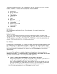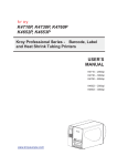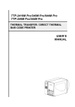
1
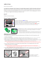
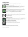
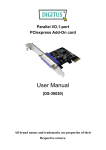
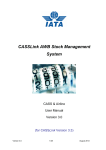
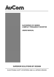
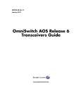
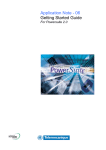
SMILODON
USERS MANUAL
Letter to User
Dear valued customers,
On behalf of the Raidmax team, thank you for purchasing our product. With the booming of the gaming market and computer cases, Raidmax would like to differentiate ourselves from other case companies by continuously providing high quality and innovative next generation cases. If you have any
critiques or comments, please feel free to send us and email. After all, we are designing the cases for
you. Thank you again for purchasing our Raidmax case.
Sincerely,
Eric Lin
Raidmax General Manager
Power Supply Installation
1. Unscrew side panel.(BLUE Circles)
2. Delatch side panel by unclicking the side panel latch and pulling.
3. Insert power supply accordingly inside the computer case.
4. Screw in 4 screws at the back of the computer case.(RED Circles)
NOTE: This step maybe skipped if you computer has a preinstalled powersupply.
Accessory Box
Included with your case is a small accessory box that houses hard drive racks,small screws and necessary hardware. It is located under the hard drive rack.
1. To pull out the box; push down on the flap and then pull out.
2. To open the box; push the thumb hole area in then push up.
Motherboard Installation
Your Raidmax case supports the following motherboards: ATX, Baby ATX, Mini ATX and Micro ATX.
1. Unscrew side panel.
2. Open the side panel by unclicking the side panel latch and pulling.(Panel doesn’t need to be removed.)
3. Remove your motherboard from its packaging and match up rectangular screw brackets.
4. Remembering which rectangular screw brackets are needed, remove the motherboard and simply
click in each provided screw bracket accordingly. (brackets are located in the accessory box)
NOTE: To install screw bracket insert one end of the bracket into the rectangular hole. Once this is done, squeeze the screw
bracket together from the other end and push down. Extra holes are normal, your case supports many motherboards.
NOTE: Before screwing in the motherboard, make sure all necessary components that need to be attached to the
motherboard are attached, such as fan mounts. When screwing in the motherboard, it is recommended to use the
provided RED circular washers, though not necessary.
5. Once all the rectangular screw brackets are installed, place your motherboard on top of the
brackets and screw in accordingly.
6. Once the motherboard is secure, plug in the 20/24 pin ATX power connector from the power supply
and also plug in ATX +12V connector if necessary. Please see your motherboard manual for full installation
0.1
0.2
0.3
0.1 Rectangular screw brackets
0.2 Provided screw bracket
0.3 Motherboard installation step 4
Front Panel Wiring Installation
Your front panel has several wire connections that need to be installed. This section provides you with a
breif description of each wire and how to install them.
Front panel leads
Inside the case there are several leads that need to be plugged in; power switch lead, power LED lead,
reset switch lead, and hard drive status lead.
1. Power LED lead(power the LED “teeth”)
The blue wire is +12V and the white wire is ground.
This wire plugs into any ATX 4 pin molex connector from the power supply.
2. Power switch lead(Power Switch Plug)
3. Reset switch lead(Reset Switch Plug)
4. Hard drive LED status lead(Flashed when hard drive is in use)
The orange wire is a positive(+) charge and the white wire is a negative(-) charge
This wire plugs into the motherboard where all the front panel switch/pin connectors functions are located.
The motherboard manual will have a concise descripiton of where to plug this in, usually in the motherboard manual the location is labeled “POWER ON BUTTON or POWER SW”.
The blue wire is a + charge and the white wire is a - charge
This wire plugs into the motherboard where all the front panel switch/pin connectors functions are located.
The motherboard manual will have a concise descripiton of where to plug this in, usually in the motherboard
manual the location is labeled “RESET BUTTON or RESET SW”.
The red wire is a positive(+) charge and the white wire is a negative(-) charge
This wire plugs into the motherboard where all the front panel switch/pin connectors functions are located.
The motherboard manual will have a concise descripiton of where to plug this in, usually in the motherboard
manual the location is labeled “Hard drive LED or HDD LED”.
USB port installation
This section tells you how to connect the USB ports at the front of the case.
1. USB 2.0 Cable Description
Inside your case are 2 USB 2.0 cables. These cable are labeled on the black leads. Each cable has a 4 pin lead and a single lead. The 4 pin lead has the following connections; USB +5V, USB_P1-,
USB_P1+, and GND. The single lead is a connector labeled “NC”.
2. USB 2.0 Cable Installation
Find the “USB Headers/Pin connectors” on the motherboard.
Plug in the wires according to the motherboard manual.
Diagram 1.1 is a general diagram and may not resemble your specific motherboard.
NOTE: If you have and extra single lead labeled NC, and there is no pin for it, leave it disconnected
Audio port installation
This section tells you how to connect the headphone and microphone jack at the front of the case.
1. Audio Port Cable Description
2. Audio Port Cable Installation
Inside your case is a single ended audio cable that connects 2 cables together. This is your front
audio port connector. This wire has 7 single lead connectors labeled as the following; LINE-OUT-R,
BLINE-OUT-R, LINE-OUT-L, BLINE-OUT-L, MIC PWR, MIC2, & AGND
Find the “Front Panel Audio Headers/Pin connectors”
Plug in the wires according to the motherboard manual.
Diagram 1.2 is a general diagram and may not resemble your specific motherboard.
Peripheral Installation
This section explains how to install your 5.25”, 3.5”, PCIExpress, PCI, and AGP devices.
5.25” Device Installation
1. Remove the corresponding drive cover and metal plate from the front of the case.
2. Locate the GREEN click lock device
3. Turn the click lock device counter clock wise to unlock it.
4. Insert your 5.25” Device and make sure the screw holes line up with the case holes.
5. Insert the GREEN click lock device and turn clockwise to lock device.
3.5” Device Installation
1. Remove the corresponding drive cover and metal plate from the front of the case.
2. Locate the GREEN click lock device
3. Turn the click lock device counter clockwise to unlock it, then remove it.
4. Insert your 3.5” Device and make sure the screw holes line up with the case holes.
5. Insert the GREEN click lock device and turn clockwise to lock device.
6. Plug in wires accordingly
3.5” Hard Drive Installation
1. Locate the hard drive brackets in the accessory box.
2. Insert 1 bracket in corresponding holes, on each side of the hard drive being installed.
3. Slide hard drive into the hard drive rack until your hear a click.
4. Plug in wires accordingly
PCIExpress, AGP, PCI Card Installation
1. Remove enforce bar by pulling the button toward the front of the case then pull it out.
2. Remove corresponding expansion slot cover with a phillips screwdriver by inserting it in the + shaped hole and flipping the slot cover toward the front of the case.
3. Remove the slot cover by bending it back and forth
4. Insert PCIExpress/AGP/PCI card accordingly.
5. Screw in PCIExpress/AGP/PCI card.
6. Reinsert enforce bar by pushing it in until it clicks.
7. Push in corresponding enforce PCIE/PCI/AGP stabilization bar.
If you have any further questions or comments, feel fee to e-mail us at:
[email protected]
Thank you for your purchase!