1
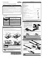
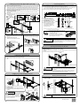
Packing List Quick-Start-Guide Make sure that the items in the following list are included in the shipping package. 43cm/17" TFT Rack Console (RC25) Preface Thank you for purchasing the 17-inch Rack Console (RC25). In this guide, you can find precautions and information about unpacking this product, checking and installing the items in the package, and connecting the cables. This guide contains important safety precautions that must be taken when you unpack/install this product and connect the cables. Carefully read and thoroughly understand this guide before performing operations. The attached CD-ROM (User's Manual) and "Safety Precautions and Other Important Information" also provide important information for using this product safely. Carefully read these documents as well before using this product, in order to ensure safe and correct use. Keep these documents handy for reference at all times. Rack Console 1 Accessories: Monitor cable (3m) PS/2 (Keyboard) cable (3m) PS/2 (Mouse) cable (3m) USB cable (3m) AC power cable (3m) Cable tie Cable management part 1 Cable management part fixing pin 1 Support bracket 1 4 2 Security lock Unlocking tool 4 1 Documents: Quick-Start-Guide (This guide) 1 CD-ROM 1 (Used for installation in an asym. PRIMERGY rack) Rack mount parts: Cage nut M5 Centering screw M5 Torx T20 (Used for installation in an asym. PRIMERGY rack) Conventions Symbols and terminology that are used in this guide are described below. This symbol indicates the possibility of physical damage (such as damage to this product) or physical injury, which may result through improper operation. CAUTION This symbol indicates comments or hints. supplemental 1 1 1 1 1 6 (User's Manual + Quick Start Guide + Warranty Sheet) 1 Safety Precautions and Other Important Information information, Double quotations Double quotation marks are used to indicate the title of a chapter or document to be referenced, or important terms. Sequential numbers Sequential numbers preceding text indicate the order of operations described by the text. Circled numbers Circled numbers in a figure indicate the order of operations. Unpacking (1) Open the package box and remove the top board. This guide is located on top of the device. (2) Remove the accessory box. Assembling the Cable Management Part (1) Remove the cable management part, monitor cable, keyboard and mouse cables (two PS/2 cables or one USB cable), AC power cable, and six cable ties from the accessory box. (2) Use cable ties to anchor the cables to point "a" on the cable management part, and continue anchoring them to points "b", "c", "d", "e", and "f". Monitor cable and keyboard and mouse cables have a white marking that indicates the point on the cable to be fixed at point "a" on Point AC power cable connector bush the cable management part. "a" There is no marking on the AC power cable. Align the end of the housing of the monitor cable with the base of the AC power cable bush, and anchor them to point "a". This will allow the cables to be installed without any Monitor cable connector slack when connected to the back of the Standard alignment position Rack Console. Attach cables on the folded cable management part without any slack in the b b e cables. a c (3) Open the plastic bag and remove the Rack Console. d c Make sure to open the plastic bag before removing the device. PS/2 cable (MS) Put your hands in the two square spaces A and B on the front and rear of the Rack Console. Firmly support the bottom of the device while removing it from the package. PS/2 cable (KB) Monitor cable f e d AC power cable Arrange the cables as shown in the figures: AC power cable on bottom with the monitor cable on top, and the keyboard and mouse cables to the side. (The figures show the cables anchored at point "a".) Top board Plastic bag Accessory box Quick-Start-Guide Rack Console PS/2 (Keyboard) cable Monitor cable Monitor cable USB cable PS/2 (Mouse) cable AC power cable AC power cable Cable tie A B Cable tie When using a USB cable for the keyboard and mouse When using PS/2 cables for the keyboard and mouse Attach cables on the folded cable management part, and arrange them as indicated without any slack in the cables between fixing points. Slack cables may dangle unnecessarily when the device is installed. Removing the RC25 Rack Mount Kits A B CAUTION When you open the package, check for damage to the product. When you remove the product from the package, open the plastic bag that covers the device and directly hold the device to lift it. Otherwise, you may drop the device and it may cause personal injury or damage the device. (1) Loosen the finger screws on the right and left front ends, and then remove the slide fixing brackets. (2) Remove the RC25 Rack Mount Kits. Outer member RC25 Rack Push the fixing springs to unlock Intermediate member Mount Kits the RC25 Rack Mount Kits, and then pull them out backwards. Rack Console (3) Unlock the intermediate member locks of the slide rails and store the intermediate members in the outer members. 固定バネ Fixing spring Intermediate member Retainer Slide fixing bracket for transport We recommend keeping the box and packing material in which the Rack Console was purchased. They may be required if you move the device to another location. If something is missing from the package, contact your supplier or local Fujitsu representative/engineer. (4) Remove the spring locks on the rear side of the RC25 Rack Mount Kits. Finger screw Spring lock Keep the removed slide fixing brackets and spring locks in a safe place. They may be required if you move the device to another location. Installing the RC25 Rack Mount Kits to the Rack Connecting Cables (1) Attach one cage nut on each of the right and left front-side rack braces, and attach another cage nut on the left rear-side rack brace. (2) Insert the two protrusions on the rear side of the RC25 Rack Mount Kits into the rear-side rack braces, so that the inserted RC25 Rack Mount Kits are at the same height unit (U). One RC25 Rack Mount Kit is for the left rear-side rack brace and the other is for the right. Find the letters LEFT or RIGHT on the side of each RC25 Rack Mount Kit and attach each RC25 Rack Mount Kit to the suitable side of the rack. (1) Turn off all devices that are connected to the RC25, except for hot-plug connections. (2) Connect the PS/2 (or USB) cable and monitor cable to this device. The Virtual Media Port (USB) is used to connect a Virtual Media KVM switch (sold separately) to this device. For more information, see the User's Manual for the KVM switch you are using. (3) Plug the AC power cable connector into the power socket on this device. (3) Keep the RC25 Rack Mount Kits horizontal at the same height unit (U) and attach them to the front-side rack braces. Check that the Easy mounting-clips and centering screws are inserted firmly into the front-side rack braces. (4) Insert the Security locks into the left and right Easy mounting-clips on the front side of the RC25 Rack Mount Kits. Easy mounting-clip Cage nut Security Rear-side lock rack braces Protrusions Front-side rack brace Cage nut Centering screw RIGHT Cage nut RC25 Rack Mount Kits Security locks Cage nut Front-side rack braces Rear-side rack brace VisualMedia MediaPort Port (U Virtual (USB)* AC power ACコード cable Monitor モニタ cable ケーブル PS/2 PS/2 cable ケーブル (KB) (KB) USB cable USB ケーブル PS/2 PS/2 cable ケーブル (MS) (MS) port Power outlet Monitor モニタポート 電源コンセント Keyboard and mouse ports キーボード・マウスポート (either USB or PS/2) (USB、PS/2どちらか一方を接続) * Remark: virtual media cable has to be ordered optionally. Connector color is gray, to distinguish from USB keyboard/touch-pad cable (black connector) Cage nut LEFT (4) Connect the cables to the monitor port, keyboard port, and mouse port on the server or a KVM switch. (5) Plug the Rack Console's power cable into the power outlet. (6) Make sure that all connections are completed before turning on the power of the Rack Console, server, KVM switch, and other devices. To remove the RC25 Rack Mount Kit: To install in an asymmetrical PRIMERGY rack: (1) Use two centering screws (M5 Torx T20) to (1) Insert the unlocking tool between the Easy mounting-clip and the Security lock as shown in install the support bracket on the left rear-side the figure, and then remove the Security lock. rack brace. (2) Install the RC25 Rack Mount Kit. See above for the installation procedure. Connect the following cables to this device as shown in this figure, so there is no slack. AC power cable on bottom Monitor cable on top If the cables are pulled too tightly after connecting the monitor cable to this device, adjust the lengths of the cables. CAUTION Left rear-side rack brace (asymmetrical PRIMERGY rack) Select either the PS/2 cable or USB cable as the cable to connect the keyboard and mouse. If both cables are connected and any operational problem occurs on the keyboard or mouse, the server must be rebooted. Centering screws M5 Torx T20 Front-side rack brace (2) Insert the unlocking tool into the opening in the Easy mounting-clip, disengage the lock, and then remove the RC25 Rack Mount Kit from the front-side rack brace. Support bracket Opening and Closing the Monitor To open the monitor (1) Grip the monitor handle and open the monitor upward. To close the monitor (1) Make sure that nothing is connected to the Virtual Media USB port on the front side of the device. (2) Hold the handle and slowly close the monitor downward. Handle Inserting the Rack Console (1) Pull out the intermediate members of the slide rails until the members are locked. (2) Pull out the retainers to the front ends of the rails. (3) Insert the Rack Console into the slide rails. Push the Rack Console until it locks on the slide rails. Retainer Virtual Media Port (USB) CAUTION When you open the monitor upward, if you cannot open it with one hand or you feel it is too heavy to open with one hand, open it with both hands. When closing the monitor, make sure there is nothing connected to the front Virtual Media USB port, and be careful to not pinch your fingers between the monitor and the keyboard. Installing the Cable Management Part (1) Secure the rear bracket of the cable management part with the finger screw on the rear protrusions of the RC25 Rack Mount Kit on the left rear-side rack brace. Storing the Rack Console (1) Push the fixing springs on the ends of the right and left slide rails, and slide the device back into the rack slowly. (2) Tighten the finger screws on the right and left front ends of the device. Rear bracket (2) Fix the front bracket to the fitting on the rear of the Rack Console. (3) Insert the pin for fixing the cable management part into the hole. Firmly push the pin until the ball lock is securely in place. If the ring for removing the pin rests on the Rack Console or RC25 Rack Mount Kit after the pin has been inserted, it might not be possible to store the Rack Console. Therefore, be sure that the ring rests on the center of the unit as shown in this figure. CAUTION Ring for removing the pin Pin for fixing the cable management part Bracket Finger screw Finger screws CAUTION Be careful not to pinch your hands or fingers in the slide rails or Rack Console itself when you stow the Rack Console. NC14010-L593-02
![SERVIS Drawer 17inch [FD-1100AT] User`s Manual](http://vs1.manualzilla.com/store/data/005815433_1-e0ce1fd89f0d0c8bc9b31edbdc395367-150x150.png)