1
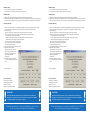
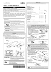
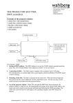
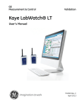
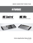
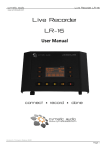
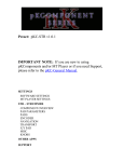
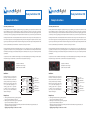
Relay SwitchBox USB
Setup Instructions
Relay SwitchBox USB
Setup Instructions
About Relay SwitcherBox USB:
About Relay SwitcherBox USB:
The Relay Switch Box USB is designed for anybody working in project, dubbing, or post production studios who needs
visual confirmation of when a recording begins or ends. This simple, precise and easy to use device is perfect for
musicians and sound engineers as well as film, tv and video editors. The device has its own visual signalling system as well
as an ability to control any signalling systems already installed in the studio. It is easy to install in any studio environment.
The Relay Switch Box USB is a small USB powered unit which controls two internal relays and one 12 V output to connection of external lights, such as Recording Display, Recording Lamp or Recording Strip. An application (Pro Tools, Cubase,
Logic Pro etc.) automatically sends information about Recording start/stop and record “ready” to the Relay Switch Box USB.
The unit is powered directly from USB. No PSU is needed in case of relays connection !
The unit is powered directly from USB. No PSU is needed in case of relays connection !
The Relay Switch Box USB takes the PunchLight product line into a new direction. You can control different devices,
e.g. speakers, a microphone or even your own light system via one small additional box. The Relay Switch Box USB can
work without a power supply, connected and powered just via a 5V USB port. In this case you can use both relays without
any limitation.
It is possible to connect one additional external light, such as the Recording Display, Lamp or PlexSign to an RJ10 output.
A 12V power supply is needed in this case. The 12V PSU is not supplied in the package.
It is possible to connect one additional external light, such as the Recording Display, Lamp or PlexSign to an RJ10 output.
A 12V power supply is needed in this case. The 12V PSU is not supplied in the package.
1) Input for a 12V DC PSU
2) Output for an external light
3) USB connection to PC/MAC
1) Input for a 12V DC PSU
2) Output for an external light
3) USB connection to PC/MAC
USB
INPUT CONTACT
SWITCHING CONTACT
(RECORD, PREROLL,
DISABLED)
CUSTOM SWITCH
ACTION RL-2
(RECORD, PREROLL,
DISABLED)
USB
RELAY 1
SWITCHING CONTACT
CUSTOM SWITCH
ACTION RL-1
TERMINAL BLOCK
(RECORD, PREROLL,
DISABLED)
CIRCUIT
OPENING CONTACT
INPUT CONTACT
The first connection is easy, just connect
the unit to an USB port on your PC or
Mac via USB cable. There are two ‘identical Relay connectors, Relay 1 and Relay 2.
Both of the relay connectors will „switch
on“ or „switch off“ depending on an
incoming signal from an application.
So devices can be connected to the
pins in a way so as to switch off devices,
instead of switching on.
CIRCUIT
OPENING CONTACT
TERMINAL BLOCK
CUSTOM SWITCH
ACTION RL-2
CIRCUIT
OPENING CONTACT
RELAY 2
(RECORD, PREROLL,
DISABLED)
TERMINAL BLOCK
CUSTOM SWITCH
ACTION RL-1
TERMINAL BLOCK
Installation:
RELAY 2
The first connection is easy, just connect
the unit to an USB port on your PC or
Mac via USB cable. There are two ‘identical Relay connectors, Relay 1 and Relay 2.
Both of the relay connectors will „switch
on“ or „switch off“ depending on an
incoming signal from an application.
So devices can be connected to the
pins in a way so as to switch off devices,
instead of switching on.
RELAY 1
Installation:
CIRCUIT
OPENING CONTACT
INPUT CONTACT
SWITCHING CONTACT
INPUT CONTACT
SWITCHING CONTACT
Example uses:
Example uses:
1. Switching off an external device, eg muting speakers
Typical connection: middle pin and „A“ pin.
2. Switching on an external device, eg turn on light system
Typical connection: middle pin and „B“ pin
Warning: the unit was approved by testing for safety to be fit for max of 50 V. We cannot guarantee the safe
usage when the voltage exceeds 50 V.
Applying a higher voltage is at the user`s own risk!
Hardware Setup
Hardware Setup
1. Connect cables from your system to green terminal plate
2. Connect the unit to an USB port on your computer using a USB cable.
1. Connect cables from your system to green terminal plate
2. Connect the unit to an USB port on your computer using a USB cable.
Software Setup
Software Setup
1. Download and run the software utility (download from www.punchlight.com/download)
2. Setup the Relay Switch Box USB as a Mackie HUI controller in your host application (Pro Tools, Logic Pro, Nuendo etc).
Please refer to the host application‘s user manual. Use the input and output ports as displayed in the utility window.
PunchLight USB Utility
PunchLight USB Utility
1. Switch on (Overrides automation) - the Red LED or Yellow LED will be on permanently, and will ignore incoming
information about recording. Switching red or yellow LED on manually disables automatic functions.
2. Relay 1 switched by:
• Red: relay 1 responds to the incoming signal from the start thru to the end of recording
• Yellow: relay 1 responds to the incoming signal depending on the application mode selected
*Pro Tools: from pre-roll to the start of recording
*Generic (e.g. Cubase, Logic etc.): from the start of the playback to the start of the recording
and from the stop of the recording to the stop of the playback
• Any: relay 1 responds to the both incoming signals
• Off: relay 1 doesn’t respond to any incoming signals
• On: manually switching the relay 1
3. Relay 2 switched by: the same as with Relay 1 function
4. Application mode - the default
application mode is set to “Pro Tools”.
“Generic (HUI)” lets the unit work with
applications such as Nuendo, Cubase,
Logic Pro, Digital Performer
or Samplitude.
5. Yellow LED automation – if disabled,
it is never on (independent on incoming
signal)
The device is ready to use.
The device is ready to use.
Technical specification
Technical specification
One device per one USB port
Input Voltage - 5V DC (USB)
Max Current 200mA
Weight - 0,2 kg (including 2m cable)
One device per one USB port
Input Voltage - 5V DC (USB)
Max Current 200mA
Weight - 0,2 kg (including 2m cable)
DISCLAIMER
DISCLAIMER
The Relay SwitchBox USB is intended for use up to a maximum power of 50 V (ELV) and 5 A.
The supplier is not responsible for its use over 50 V and 5 A, or for any alteration or adjustment
to the product, and the user proceeds at his or her own risk.
The Relay SwitchBox USB is intended for use up to a maximum power of 50 V (ELV) and 5 A.
The supplier is not responsible for its use over 50 V and 5 A, or for any alteration or adjustment
to the product, and the user proceeds at his or her own risk.
Mediaport Pro | Hradesinska 67 | 101 00 Praha 10 | Czech Republic | Tel. + 420 271 735 610
Fax. + 420 272 734 897 | [email protected] | www.punchlight.com
Mediaport Pro | Hradesinska 67 | 101 00 Praha 10 | Czech Republic | Tel. + 420 271 735 610
Fax. + 420 272 734 897 | [email protected] | www.punchlight.com