1
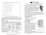
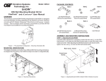
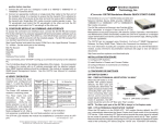
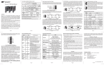
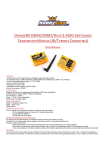
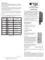
4) Verify Operation
Once the module has been installed and configured, per steps 1 - 3, verify the module
is operational by viewing the status of the LED indicators. The table below provides a
description for each indicator.
iConverter® NMM2
Network Management Module
The Power LED indicates the module is receiving power from the chassis. The NMM2
has an LED indicator for each available power supply in the chassis (19-Module Chassis
has three, 5-Module Chassis has two).
The Master/Slave and Management LEDs indicate the operation and configuration
of the management channel. A blinking “Mgt” LED indicates the NMM2 is polling the
chassis.
The UTP “10” or “100” LED indicates the module has established a connection across
its UTP port. A blinking LED indicates the presence of data.
LED Function
“Legend”
Color
OFF State
ON / Blinking State
QUICK START GUIDE
The iConverter NMM2 provides real-time management, trap
notification and remote configuration of iConverter equipment.
It supports SNMPv1, SNMPv2c, SNMPv3 and Telnet protocols.
SMNPv3 provides secure access to devices by a combination
of authenticating and encrypting packets over the network.
For more information, including the complete User Manual
on the NMM2 module, access Omnitron’s documentation
download web page to view all relevant documents:
Power
“Pwr”
Green
No Power
Module has power
http://www.omnitron-systems.com/downloads_iconverter.php
Power Supply Status
“PSx”
Green
Power Supply not installed
ON: Power available
Blinking: Supply installed but not powered
Master/Slave
“Msr/Slv”
Installation Procedure
1) Configure DIP-Switches
Green
Slave Mode
ON: Chassis Master
2) Install Module in Chassis and Connect Cables
Management
“Mgt”
Green
Not polling chassis
ON: Polling chassis
3) Configure Module via Command Line Interface
10Mbps (UTP)
“10”
Green
10Mbps not selected or
disconnected
ON: Active 10Mbps UTP link
Blinking: UTP data activity
100Mbps (UTP)
“100”
Green
100Mbps is not selected or
disconnected
ON: Active 100Mbps UTP link
Blinking: UTP data activity
Full-duplex (UTP)
“FDX”
Green
Half-duplex
Full-duplex
4) Verify Operation
1) CONFIGURE DIP-Switches
DIP-Switches
The location of the DIP-switch is illustrated in Figure
A and the description is shown in Figure B.
Figure D: LED Indicators
SW1 - Pause
When the UTP port is operating in Auto-Negotiation,
its Pause operation mode is determined by the Pause
capability advertised during AN between itself and the
link partner. The port advertises its Pause capability
(Symmetrical or No Pause) during AN based on the
Pause Disable/Enable DIP-switch setting.
When a port is operating in Manual mode, its Pause
operation mode is based on the Pause Disable/
Enable DIP-switch setting.
SW2 - RESERVED
NOTE: DIP-switches marked Reserved must be kept in the Left (factory default)
position.
040-8000N-001 A
Omnitron Systems Technology * 140 Technology Dr. #500 * Irvine, CA 92618
949.250.6510 tel * 949.250.6514 fax * www.omnitron-systems.com
3/09
SW3 - UTP Auto/Manual
When this DIP-switch is in the UTP Auto Negotiate “AN” position (factory default), the
UTP port automatically determines the speed and duplex mode of the connecting UTP
device. DIP-switches SW3, SW4 and SW5 determines the speed and duplex modes
advertised by the module. See Figure C on the following page for more information.
Switch
Left (Default)
Right
SW1
OFF:
Pause Disable
PAUS:
Pause Enable
SW2
RESERVED
SW3
AN:
UTP Auto-neg.
MAN:
UTP Manual
SW4
100:
UTP 100Mbps
10:
UTP 10Mbps
SW5
FDX:
UTP Full-duplex
HDX:
UTP Half-duplex
SW6
A-DS: Disabled
Backplane Port A
A-EN: Enabled
Backplane Port A
SW7
B-DS: Disabled
Backplane Port B
B-EN: Enabled
Backplane
Port B
SW8
RESERVED
Figure B: DIP-switch Description
SW4 - UTP 10/100Mbps
When the UTP “AN/MAN” DIP-switch is in the manual “MAN” position, the “10/100”
DIP-switch determines the speed of operation for the UTP port.
SW5 - UTP Full/Half Duplex
When the UTP “AN/MAN” DIP-switch is in the manual “MAN” position, the UTP
Full/Half-Duplex “FDX/HDX” DIP-switch determines the duplex operation mode of the
UTP port.
SW3
AN
AN
AN
SW4
100
100
10
SW5
Function
FDX
The UTP port is set to Auto-Negotiation
with the following modes advertised:
100F, 100H, 10F, 10H
HDX
The UTP port is set to Auto-Negotiation
with the following modes advertised:
100H, 10F, 10H
FDX
The UTP port is set to Auto-Negotiation
with the following modes advertised:
10F, 10H
AN
10
HDX
The UTP port is set to Auto-Negotiation
with the following modes advertised:
10H
MAN
100
FDX
The UTP port is set to Manual
Negotiation and is forced to: 100F
MAN
100
HDX
The UTP port is set to Manual
Negotiation and is forced to: 100H
MAN
10
FDX
The UTP port is set to Manual
Negotiation and is forced to: 10F
HDX
The UTP port is set to Manual
Negotiation and is forced to: 10H
MAN
10
Figure C: Speed and Duplex Settings
SW6, SW7 - A/B backplane enable
The NMM2 can be configured for In-Band or Out-of-Band management. When the
Backplane Enable switch is in the “DS” position (factory default), the front-panel UTP
management port is enabled and the Backplane Ethernet Port is disabled. This is
defined as Out-of-Band management. When the DIP-switch is in the “EN” position, the
Backplane Ethernet Port is enabled. This is defined as In-Band management. This
allows Ethernet Backplane connectivity to adjacent modules via the chassis Backplane
“A” or “B” depending on the switch setting. Refer to the full version User Manual for
the appropriate A/B backplane configuration settings.
SW8 - RESERVED
NOTE: DIP-switches marked Reserved must be kept in the Left (factory default)
position.
2) Install Module in Chassis and Connect Cables
a. It is recommended that the NMM2 be installed in Slot 1. Carefully slide the module
into the open slot in the chassis. Align the module with the installation guides and
ensure that the module is firmly seated against the backplane. Secure the module
by fastening the front panel thumbscrew (push in and turn clockwise to tighten) to
the chassis front. Verify the “Pwr” LED is ON (indicating the chassis is powered).
b. Connect the UTP port via a Category 5 cable to a 10BASE-T or 100BASE-TX
Ethernet device (Management Station).
3) Configure Module via Command Line Interface
To access the Command Line Interface (CLI), connect the NMM2 RS-232 Serial Console
Port to the COM port of a computer equipped with terminal emulation software such as
HyperTerminal. The Console Port (DCE) is a mini DIN-6 female connector which can
be changed to a DB-9 connector with the included adapter. The NMM2 Console Port
is a standard RS-232 asynchronous serial interface.
Start HyperTerminal and select the correct COM Port in the HyperTerminal “Connect
To:” window. Set the serial port to the following:
Bits Per Second 57,600
Stop Bits 1
Data Bits 8
Parity
NONE
Hardware Flow Control
NONE
Once connected, press <ENTER> to bring up a command line prompt on the attached
PC. A new NMM2 module does not have a password, and will skip the Password Entry
screen and go straight to the Management Options screen. If a password has been set,
the Password Entry screen will be displayed. Type the password and press <ENTER>,
the NMM2 will respond with the Management Options screen.
From the Management Option screen, it recommended to configure:
•
serial port password - option 3 from the Management Options screen
•
telnet password - option 3 from the Management Options screen
•
IP address of the module - option 3 from the Management Options screen
•
SNMP parameters - option 4 from the Management Options screen
See the full version of the User Manual for more information.