1
Transportation Products CBT mVEC User Manual Table of Contents 1. mVEC Introduction Section ................................................................................................... 4 2. Quick Start Section ................................................................................................................... 6 2.1. Working with the mVEC.............................................................................................................. 6 2.1.1. mVEC Electrical Grid ........................................................................................................... 6 2.1.2. mVEC Components ............................................................................................................. 6 2.1.3. Component Descriptions...................................................................................................... 6 2.1.4. mVEC Software ................................................................................................................... 7 3. Configuring the mVEC Options ............................................................................................ 8 3.1. Hardware Options ...................................................................................................................... 8 3.1.1. mVEC Electrical Grid Configuration Options........................................................................ 8 3.1.2. External High-Side Output Option ........................................................................................ 9 3.1.3. Grid Output Connector Options............................................................................................ 9 3.1.4. Grid Input Power Connection Options.................................................................................. 9 3.1.5. Grid Label Options ............................................................................................................... 9 3.1.6. Cover Options .................................................................................................................... 10 3.1.7. Fuse Puller and Spare Fuse Options ................................................................................. 10 3.2. Software options ....................................................................................................................... 10 3.2.1. Fault Detection Options ..................................................................................................... 10 4. External Connections ............................................................................................................. 11 4.1. Control Header Connection ...................................................................................................... 11 4.1.1. Overview ............................................................................................................................ 11 Figure 8: CAN (mating) connector ................................................................................. 12 4.1.2. CAN Connector Part Numbers ........................................................................................... 12 4.1.3. CAN Connector Pin Descriptions ....................................................................................... 12 4.1.4. Ignition Connections .......................................................................................................... 13 Figure 9: Active-low ignition connections....................................................................... 14 Figure 10: Active-high ignition connections ................................................................... 15 Figure 11. CAN harness address pin connections with power reference to offset ........ 16 4.2. Bussman 32006 Series Output Connections ............................................................................ 16 4.2.1. Part Numbers ..................................................................................................................... 16 4.2.2. Output Connector Drawing ................................................................................................ 17 4.3. mVEC Power Input Connection Options................................................................................... 18 4.3.1. Bladed Power .................................................................................................................... 19 4.3.2. Studded Power .................................................................................................................. 19 Figure 14. Studded power (mating) connector.............................................................. 19 4.3.3. Input Connector Part Numbers .......................................................................................... 20 Figure 15. Bussmann 32004 VEC Input connector....................................................... 20 5. Vehicle Installation ................................................................................................................. 21 5.1. Mechanical Information ............................................................................................................ 21 5.1.1. Dimensions ........................................................................................................................ 21 Figure 18. mVEC height with cover open ..................................................................... 22 1 5.1.2. Mounting Location Selection .............................................................................................. 22 5.1.3. Electrical Connections to the Vehicle ................................................................................. 23 5.1.4. Power Connections to the mVEC: Connector Details ........................................................ 24 5.1.5. High-Side Drive (Optional) ................................................................................................. 25 5.1.6. CAN Connection ................................................................................................................ 25 Figure 21. CAN connection........................................................................................... 26 6. Application Examples ............................................................................................................ 27 6.1. Switched Fuse Load ................................................................................................................. 27 6.2. Inductive Load Protection ......................................................................................................... 27 6.3. Controlling a Motor using an H-Bridge...................................................................................... 28 Table 4. H-Bridge States for Motor Control .................................................................. 28 Figure 24. H-bridge....................................................................................................... 29 6.4. Controlling Flashers using Relays ............................................................................................ 29 6.5. High-Side Output Power Master ............................................................................................... 30 7. PROGRAMMING the mVEC (Using J1939 Messages to Set, Control, and Monitor the mVEC) ...................................................................................................................... 31 7.1. CAN Software Settings ............................................................................................................. 31 7.1.1. Proprietary A Messages..................................................................................................... 31 7.1.2. CAN Source Address ......................................................................................................... 31 Table 5. CAN Harness Address Pin States and Offsets ............................................... 33 7.1.3. Parameter Group Number (PGN) Base for Proprietary B Messages ................................. 33 7.1.4. Population Table ................................................................................................................ 34 7.1.5. Default Relay States .......................................................................................................... 35 7.1.6. Start-up Delay Time ........................................................................................................... 35 7.1.7. CAN Message Count Threshold ........................................................................................ 36 7.1.8. Software Version Number .................................................................................................. 37 7.1.9. Controlling Relays .............................................................................................................. 37 7.2. Monitoring Fuse, Relay, and System Fault States.................................................................... 38 7.2.1. Proprietary B Messages..................................................................................................... 38 7.2.2. Fuse Status Messages ...................................................................................................... 39 7.2.3. Relay Status Messages ..................................................................................................... 39 7.2.4. System Error Status Messages ......................................................................................... 39 7.3. CAN Message Definitions......................................................................................................... 40 7.3.1. Proprietary A Messages..................................................................................................... 40 7.3.1.1 Command Messages .................................................................................................. 39 Table 6. Message ID 0x12 (Command) ........................................................................ 40 Table 7. Message ID 0x80 (Command) ........................................................................ 41 Table 8. Relay State Values ......................................................................................... 41 Table 9. Message ID 0x88 (Command) ........................................................................ 42 Table 10. Message ID 0x90 (Command) ...................................................................... 42 Table 11. Message ID 0x92 (Command) ...................................................................... 41 Table 12. Message ID 0x94 (Command) ...................................................................... 43 Table 13. Message ID 0x95 (Command) ...................................................................... 44 Table 14. Message ID 0x96 (Command) ...................................................................... 45 Table 15. Message ID 0x98 (Command) ...................................................................... 44 Table 16. Message ID 0x98 (Command) ...................................................................... 46 2 Table 17. Message ID 0x99 (Command) ...................................................................... 46 7.3.1.2. Reply Messages ......................................................................................................... 45 Table 18. Message ID 0x01 (Reply) ............................................................................. 47 Table 19. Relay State Change Failure Message .......................................................... 47 Table 20. Message ID 0x13 (Reply) ............................................................................. 48 Table 21. Message ID 0x94 (Reply) ............................................................................. 48 Table 22. Message ID 0x96 (Reply) ............................................................................. 49 Table 23. Message ID 0x97 (Reply) ............................................................................. 49 7.3.2. Proprietary B Messages ............................................................................................................ 51 7.3.2.1. Fuse Status ..................................................................................................................... 51 Table 24. Fuse Status Message ................................................................................... 51 Table 25. Fuse Status Values....................................................................................... 52 7.3.2.2. Relay Status.................................................................................................................... 52 Table 26. Relay Status Message .................................................................................. 52 Table 27. Relay Status Values ..................................................................................... 53 7.3.2.3. System Error Status ........................................................................................................ 53 Table 28. Error Messages ............................................................................................ 54 8. Hardware Specifications ....................................................................................................... 56 Environmental Specification ............................................................................................................ 56 Electrical Specifications ................................................................................................................... 56 MAX Electrical Ratings Electrical Grid Ratings 12-Pin Connector Rating Transient Rating EMC Ratings 9. Troubleshooting ...................................................................................................................... 59 10. FAQ ............................................................................................................................................ 61 11. Glossary of Terms ................................................................................................................ 63 3 1. mVEC Introduction Section The multiplexed Vehicle Electrical Center (mVEC), shown in Figure 1, is an enhanced version of the Bussmann Vehicle Electrical Center (VEC) as it has a Controller Area Network (CAN) interface. The mVEC has VEC-like features (accepts plug-in components common to power distribution such as fuses, relays, circuit breakers, diodes, etc.) and is IP66 compliant. The mVEC incorporates the VEC ‘power grid’, an electrical component grid for power distribution functions, and the grid is electronically interfaced with a CAN control board that monitors the state of components and controls relays that are plugged into the grid of the mVEC. Figure 1. Multiplexed Vehicle Electrical Center The mVEC is a power distribution slave module that distributes power to other devices in a vehicle, and communicates over a CAN bus. Because it is a slave module, the mVEC relies on a master CAN module to control its relays and monitor component status messages. The mVEC is ideal for applications across numerous markets, including heavy truck, construction, agriculture, military, transit bus/coach, marine, recreational vehicle, and specialty vehicle applications. The mVEC is an excellent solution for power distribution systems that require the ability to control relays and monitor fuses and relays; and a cost effective replacement for complex, fully electronic (solid state) power distribution modules. The mVEC’s grid can be populated with industry standard plug-in components which use “280 series” terminals, including relays, fuses, circuit breakers, diodes, transorbs, resistors, and flasher modules. These components can be configured in many different ways to meet your system requirements. 4 The mVEC can be connected to 12 V or 24 V systems, or to vehicles with both voltages. The mVEC is based off the Bussmann VEC technology and it is possible to customize the mVEC (create a new variant) so that it is capable of functioning with varying electrical architectures. The mVEC can be enabled (turned-on) by battery voltage through an active-high ignition input or by ground through an active-low ignition input. The mVEC’s CAN control board is protected against over-voltage transients and reverse-voltage conditions and its relay coil drivers are protected from short-circuits. The mVEC communicates with other devices on the vehicle’s CAN bus using the SAE J1939 protocol, and can be part of a multiplexing system that eliminates the need for individual connections between switches and loads. The mVEC works by receiving messages to turn its relays “on” and “off”, and by sending messages indicating the state of its grid components. Figure 2 shows how an mVEC can be integrated into a vehicle. Figure 2. mVEC Integration Diagram 5 2. Quick Start Section 2.1. Working with the mVEC The mVEC is a power distribution slave module that distributes power to other modules in a vehicle over a Controller Area Network (CAN) bus. Because it is a slave module, the mVEC relies on other modules to monitor and control its components and software. 2.1.1. mVEC Electrical Grid The mVEC features the VEC ‘power grid’ (shown in Figure 3) internal to the unit. This VEC grid provides the electrical circuit to various components with 64 connection points, which can be utilized within the design. Figure 3: mVEC Grid Area 2.1.2. mVEC Components The mVEC electrical grid can be populated with components that have 2.8 mm blades on 8.1 mm centerlines (280-series components). mVEC components are used for controlling and/or fusing highcurrent loads on a vehicle, like relays and fuses. The mVEC components can be configured per the customer’s requirements. These various types of components can be placed on the mVEC electrical grid, including (but not limited to) relays, fuses, circuit breakers, diodes, transorbs, resistors, and flasher modules. The mVEC can only control and monitor relays; fuses and circuit breakers (type I & III) can only be monitored. Because of this, most of the manual is dedicated to using fuses and relays. Relays that are not controlled via the internal CAN board cannot be monitored as normal since the relay control signals are unknown. 2.1.2.1. Relays The mVEC can be populated with 4-terminal and 5-terminal relays that can switch power to loads. These relays can be controlled via CAN commands, which signal the internal driver to energize 6 the relay coils by pulling one side of the coil low. (See Grid Coil Current Limit in Section 8). The mVEC has the ability to control and monitor relays. • For information on how the mVEC controls relays, refer to section 7.1.9. Controlling Relays • For information on how the mVEC monitors relays, refer to section 7.2. Monitoring Fuse, Relay, and System Fault Status. 2.1.2.2. Circuit Protection – Fuses & Circuit Breakers Fuses and Circuit Breakers limit excessive current going to loads. The mVEC determines the state of each fuse / breaker by monitoring the fuse voltage through two internal digital inputs. The mVEC has the ability to monitor fuses / breakers (it cannot control them). Note Type II circuit breakers may not show open status due to the internal resistive component and should not be used in the mVEC. • For information on how the mVEC monitors fuses / breakers, refer to section 7.2. Monitoring Fuse, Relay, and System Fault Status. 2.1.3. mVEC Software The mVEC is a slave module, meaning it is controlled by a master CAN module over a Controller Area Network (CAN), using CAN messaging. OEMs / Integrators / operators are not able to create custom software for the mVEC. However, you can change some of the mVEC’s software settings. • For information on changing software settings, refer to section 7.1. CAN Software Settings. • For information on how the mVEC controls and monitors components, refer to section 7, Programming the mVEC. 7 3. Configuring the mVEC Options There are many elements of the mVEC that can be configured. Configuration options for the mVEC fall into two major categories, as follows: • Hardware configuration options. All hardware configuration options must be selected early in the design process and implemented before production. • Software configuration options. Most software configuration options do not need to be selected until production, and can be modified after production if needed. Contact your Cooper Bussmann Account Representative for more details about creating a custom configuration for your product. 3.1. Hardware Options 3.1.1. mVEC Electrical Grid Configuration Options The mVEC’s electrical grid has 64 connection points that are used for connecting components to the grid. The components you choose for the grid determine the hardware configuration of your mVEC. Once your configuration is created, you will receive a custom overlay for the grid that has cutouts for each component you selected. See Figure 4. Figure 4. Grid Component and Connector Location Diagram 8 3.1.2. External High-Side Output Option An external high-side output can be configured into the mVEC. This output is available on pin #11 on the 12-pin CAN connector, and can be used to drive low-current loads that are external to the mVEC such as relays, LEDs, or other system loads. 3.1.3. Grid Output Connector Options The configuration options for the output connectors are as follows: • You can have up to four different output connectors on your mVEC (refer to Figure 5). • Total current for each connector is 100 amps. • Output connectors can be sealed, or unsealed (sealed required for IP66 rating). • Output connectors can be configured in four different colors, with each color having a different keying (useful for ensuring the output connectors are connected to the correct harnesses). Figure 5. Grid Connector Location Diagram 3.1.4. Grid Power Connection Options The “Power Grid” of the mVEC has two options for the incoming current: studs or connectors. The maximum input amperage for an mVEC is 200 amps regardless of the input connection type. 3.1.5. Grid Label Options The mVEC internal surface has a label with cut outs to allow insertion of components in only the positions to be filled per the design. It also may have plug-in descriptions, and identifiers (e.g. fuse numbers, relay identifiers, labels, etc.) For each unique part number, the label is custom marked per the customer’s design. Custom marking may include customer/OEM logos, part numbering, circuit identifiers, etc. 9 3.1.6. Cover Options Additional marking is available on the mVEC cover. Custom laser etching may be made either on the mVEC interior of the cover (underside) or on the exterior (outside) or both. 3.1.7. Fuse Puller and Spare Fuse Options A fuse puller and up to 4 spare fuses can be included with your mVEC. If included, these items would be stored on the electrical grid as shown in Figure 6. Figure 6. Spare Fuse and Puller Locations 3.2. Software options The mVEC software configuration options are primarily in the area of base addressing, default states for relays, and population tables for components (whether to detect if they are present and to be monitored or ignored due to an empty plug in position). Some of the options must be configured at the factory before the mVEC is manufactured, and the rest can be configured by the user at anytime. 3.2.1. Fault Detection Options The mVEC is capable of detecting various faults. However, some faults may need to go unreported, and would need to be disabled in the factory at an early stage of development. An example would be a fuse that is supplied power through a relay contact. When the relay contact is open the fuse will not have power, causing the mVEC to detect a non-powered fuse fault. It is assumed that fuses always have power; therefore, the non-powered fuse fault should be disabled for this particular fuse. mVEC fault detection capabilities are detailed in the software section of this manual. See section 7 for more information. 10 4. External Connections System connections to the mVEC can be classified into three groups: • CAN Connector • Power Output Connectors • Power Input Connectors Figure 7. Connector locations 4.1. Control CAN Connection 4.1.1. Overview There is one CAN connector on the mVEC, as shown in the above picture. The CAN connector is a Tyco AMP connector that provides CAN communication, logic power, and logic ground signals for the mVEC. • The receptacle contacts on the CAN connector are each rated at 10 A. • When the CAN connector is mated to the harness, it is sealed to IP66 The following shows the different parts of the logic (mating) connector: 11 Figure 8: CAN (mating) connector 4.1.2. CAN Connector Part Numbers The following table shows the mating connector part numbers for the mVEC’s CAN connector: Table 1. CAN connector Part Numbers Component Part Number Plug housing Tyco (AMP) - 184115-1 Receptacle contact 20-14 AWG, Gold: Tyco (AMP) - 184030-1 Double lock plate Tyco (AMP) - 184058-1 Wire seal Tyco (AMP) - 184140-1 Cavity plug Tyco (AMP) - 172748-1 or 172748-2 4.1.3. CAN Connector Pin Descriptions The following table shows the pin-out for the CAN connector: Table 2. 12-Pin Connector Pin-Out Pin Number Name Function 1 VBATT 2 PWR_REF 3 GND_POWER Ground connection for the mVEC control circuitry and relay coil return path. Wire size must handle all the relay’s coil current. 4 ADDR_1 Base address offset bit #1. Internally pull low (logic 0). Connect to PWR_REF to change the offset address to logic 1. 5 CAN_SHIELD 6 CAN_HI 7 IGNITION_LOW Power / battery input to power the mVEC control circuitry. 12 or 24V capable. Voltage reference for the ADDR inputs to offset the mVEC source address. This is the connection point to the CAN shield. CAN bus high signal connection (CAN_H). Input enable pin. Pull this input to ground to enable the control circuitry. Typically switched with vehicle ignition, use either this pin or pin 8 for enable control. 12 Pin Number Name Function 8 IGNITION_HIGH Input enable pin. Pull this input to battery level to enable the control circuitry. Typically switched with vehicle ignition, use either this pin or pin 7 for enable control. 9 ADDR_2 Base address offset bit #2. Internally pull low (logic 0). Connect to PWR_REF to change the offset address to logic 1. 10 ADDR_0 Base address offset bit #0. Internally pull low (logic 0). Connect to PWR_REF to change the offset address to logic 1. 11 HS_OUTPUT 12 CAN_LO Optional high-side drive output, controlled via CAN command. CAN bus low signal connection (CAN_L). 4.1.4. Ignition Connections The mVEC offers two power-enable inputs pins within the CAN connector. • One is active high, called IGNITION_HIGH • One is active low, called IGNITION_LOW The mVEC will remain powered on when either signal is active. Once deactivated, the mVEC will power off, delaying shortly if internal memory requires updating. Note: Only one of the enable lines should to be used for normal operation. If both are enabled simultaneously, the mVEC will enter a recovery mode application (factory use only). 4.1.4.1. Active-Low Ignition Input Connection The active-low ignition input (IGNITION_LOW) enables power to the mVEC when the voltage is lower than ½ battery voltage on Pin 1. A shut-down procedure is activated when the voltage on the active-low input is higher than ½ battery voltage on Pin 1, or when the input has an open circuit condition. Caution: The minimum recommended fuse value for the active-low ignition input is 200 mA. This protection is only needed for the harnessing to the mVEC. The following shows a typical active-low ignition input connection: 13 Figure 9: Active-low ignition connections 4.1.4.2. Active-High Ignition Input Connection The active-high ignition input (IGNITION_HIGH) enables power to the mVEC when the input is higher than ½ battery voltage on Pin 1. A shut-down procedure is activated when the voltage on the active-high input is lower than ½ battery voltage on Pin 1, or when the input has an open circuit condition. Caution: The minimum recommended fuse value for the active-high ignition input is 200 mA. This protection is only needed for the harnessing to the mVEC. The following shows a typical active-high ignition input connection: 14 Figure 10: Active-high ignition connections 4.1.4.3. CAN Harness Address Pin Connections There are three pins dedicated to CAN harness addressing in the CAN connector, called ADDR_0, ADDR_1, and ADDR_2 CAN harness address pins are connected to a power reference (called PWR_REF) that is provided by the mVEC. The power reference should not be used for any other purpose other than for the CAN harness address pins. The following should be taken into consideration when connecting the CAN harness address pins to power reference: • The power reference can be spliced into the CAN harness address pins in the CAN connector. • Pins that need to be pulled high should be connected to the power reference. All other pins can be left open circuit. Note: Each mVEC on a single network must have a unique source address. The source address may be altered by configuring the source address offset through the mVEC’s CAN harness address pins. The following shows a typical CAN harness address pin connection: 15 Figure 11. CAN harness address pin connections with voltage reference. 4.2. Bussman 32006 Series Output Connections Bussman sells mVEC output connectors, designated 32006-xxx. The –xxx allows choices of color (8 options), type of connector cavity, and sealed or unsealed. There can be up to four output connectors on the mVEC, depending on your configuration. The output connectors are capable of providing 30 A maximum of continuous current per terminal (maximum 100A per connector)l. • When a sealed output connector is mated to the harness, it is sealed to IP66. • All output connector options are readily available through Distribution. • Each color connector has a different keying feature. 4.2.1. Part Numbers Because there are so many configuration options for the output connectors, there are a lot of different mating connector possibilities. Here is the part numbering scheme for the 32006 VEC connectors. M ALE OUTPUT CONNECTOR (280 SERIES) 32006-X X X SEALING OPTIONS 1 = Non-sealed 2 = Sealed CONNECTOR CAVITY CONFIGURATION 1 = For Use With Tangless Wire Terminals 2 = For Use With Tanged Wire Terminals P = Plugged PART COLOR A = Black E = Yellow J=Neutral (only B = Gray F = Red available with –JP2 C = Green G = Orange option.) D = Blue H = Brown 16 4.2.1.1. Terminal Position Assurance (TPA) mVEC connectors feature terminal position assurance. Here are the part numbers depending on your sealing configuration. OUTPUT CONNECTOR – TERMINAL POSITION ASSURANCE (TPA) 32006-TPX SEALING OPTION 1 = For Use With Non-sealed Terminals 2 = For Use With Sealed Terminals 4.2.1.2. Connector Position Assurance (CPA) The connector position assurance part number is 32006-CP. 4.2.2. Output Connector Drawing The output connector pinouts are configuration-specific. Refer to the procurement drawing for your specific mVEC configuration for more details. Figure 12. 32006 VEC Connector 17 Table 3. 32006 Mating Terminal Reference The chart below is for reference only, and is subject to changes by Delphi Packard. Delphi Packard part numbers are shown. PART NUMBERS TERMINALS DESCRIPTION CABLE RANGE (mm sq) GAUGE 12110843 280 ser. Metri-Pack Unsealed Female Terminal - Tangless .35-.50 22-20 12110844 12129424 280 ser. Metri-Pack Unsealed Female Terminal - Tangless 280 ser. Metri-Pack Unsealed Female Terminal - Tangless .80-1.0 1.0-2.0 18-16 16-14 12110842 12129663 280 ser. Metri-Pack Unsealed Female Terminal - Tangless 280 ser. Metri-Pack Unsealed Female Terminal - Tangless 2.0-3.0 3.0 14-12 12 12129425 12110846 280 ser. Metri-Pack Unsealed Female Terminal - Tangless 280 ser. Metri-Pack Sealed Female Terminal - Tangless 5.0 .35-.50 10 22-20 12110847 12129409 280 ser. Metri-Pack Sealed Female Terminal - Tangless 280 ser. Metri-Pack Sealed Female Terminal - Tangless .80-1.0 1.0-2.0 18-16 16-14 12110845 12110853 280 ser. Metri-Pack Sealed Female Terminal - Tangless 280 ser. Metri-Pack Sealed Female Terminal - Tangless 2.0-3.0 3.0-5.0 14-12 12-10 12052217 12034046 280 ser. Metri-Pack Unsealed Female Terminal - w/Tang 280 ser. Metri-Pack Unsealed Female Terminal - w/Tang .35-.50 .50-.80 22-20 20-18 12066214 12129494 280 ser. Metri-Pack Unsealed Female Terminal - w/Tang 280 ser. Metri-Pack Unsealed Female Terminal - w/Tang 1.0-2.0 2.0-3.0 16-14 14-12 12059284 12015858 280 ser. Metri-Pack Unsealed Female Terminal - w/Tang 280 ser. Metri-Pack Unsealed Female Terminal - w/Tang 3.0 3.0-5.0 12 12-10 12084201 12077411 280 ser. Metri-Pack Sealed Female Terminal - w/Tang 280 ser. Metri-Pack Sealed Female Terminal - w/Tang .35-.50 .50-.80 22-20 20-18 12077412 12129493 280 ser. Metri-Pack Sealed Female Terminal - w/Tang 280 ser. Metri-Pack Sealed Female Terminal - w/Tang 1.0-2.0 2.0-3.0 16-14 14-12 12077413 280 ser. Metri-Pack Sealed Female Terminal - w/Tang 3.0 12 PART NUMBERS SEALS DESCRIPTION/COLOR/TYPE CABLE DIA. 12015193 12010293 280 ser. Metri-Pack cable seal/Blue/Straight 280 ser. Metri-Pack cable seal/Light Gray/Straight 3.45-4.30 2.81-3.49 12015323 12041351 280 ser. Metri-Pack cable seal/Green/Ribbed 280 ser. Metri-Pack cable seal/Tan/Straight 2.03-2.85 2.03-2.42 12089679 280 ser. Metri-Pack cable seal/Purple/Ribbed 1.60-2.15 12015899 280 ser. Metri-Pack cable seal/Dark Red/Ribbed 1.29-1.70 12129381 800 ser. Metri-Pack cable seal 4.54-4.70 PART NUMBERS 12010300 CAVITY PLUGS 280 Metri-Pack Cavity plug for 32006-XX Connector PART NUMBER 12094429 TERMINAL REMOVAL TOOL 280 & 800 Ser. Metri-Pack Female Terminal Removal Tool 4.3. mVEC Power Input Connection Options There are two types of power input connectors that can be used with the mVEC (depending on your grid configuration): • • Bladed (using sealed dual-blade connectors) Studded (using ring terminals) 18 4.3.1. Bladed Power The Bussmann 32004 input connector is one option for mVEC current input. It mates with the dualbladed connector installed within the mVEC. There can be up to two input connectors on the mVEC, depending on your configuration. • Each input connector is capable of providing 60 A of continuous current per blade, totaling to 120 amps per connector. For maximum grid amperage, two input connectors must be used. • When an input connector is mated to the harness, it is sealed to IP66. • The 32004 is readily available through Distribution. mVEC input connectors offer somewhat superior protection for the mVEC when in corrosive environments, as compared to the studded inputs. Studded inputs have exposed metal and are susceptible to corrosion from contaminants such as road salt, etc. If the mVEC is to be installed in an external environment, bladed connectors are recommended as inputs. The two bladed power inputs within a single connector must be the same voltage (one can be unused). The second connector’s blades can have a different voltage. Figure 13. Bussmann 32004 VEC Input connector 4.3.2. Studded Power The studded input connector uses M8 or M6 studs, and is connected to the harness with ring terminals. • The recommended torque that should be used when attaching the studded power connector is 10-12 ft/lbs. The maximum torque is 18ft/lbs. • Bussmann recommends that if the studded input is used and the mounting of the mVEC is in a location where the vehicle could be exposed to corrosive chemicals such as road salts, that ‘after treatments’ be used to the input area including the following possible actions: Generous application of a dialectric grease to the entire stud assembly (cover the power input stud, the plate of the input area and over the ring terminal Use a epoxy / anti corrosive spray coating over the entire stud assembly (cover the power input stud, the plate of the input area and over the ring terminal The following shows a studded power (mating) connector: Figure 14. Studded power (mating) connector 19 4.3.3. Input Connector Part Numbers Male input connector (800 Series) M ALE INPUT CONNECTOR (800 SERIES) 32004–X X SEALING OPTION 1 = Non-sealed 2 = Sealed PART COLOR A = Black B = Gray The following drawing shows a 32004 Input Connector. Figure 15. Bussmann 32004 VEC Input connector 4.3.3.1. Terminal Position Assurance (TPA) mVEC Connectors feature terminal position assurance. Here are the part number depends on your sealing configuration. Input Connector - TPA 32004-TPX SEALING OPTION 1 = For Use with Non-Sealed Terminal 2 = For Use with Sealed Terminals 4.3.3.2. Connector Position Assurance (CPA) Input connector – CPA 32004-CP 20 5. Vehicle Installation Vehicle installation will vary depending on the system. Therefore, mechanical, environmental, and electrical guidelines and requirements that you should be aware of before installing the product have been provided. 5.1. Mechanical Information It is important that the mVEC be installed so that all of the mechanical components are easily accessible. 5.1.1. Dimensions The following diagrams show the dimensions of the mVEC in millimeters: Figure 16. mVEC width and depth Figure 17. mVEC height with cover closed 21 Figure 18. mVEC height with cover open 5.1.2. Mounting Location Selection Where you mount the mVEC is completely dependent on your system; however, you must take the following environmental and mechanical requirements into consideration before mounting. If you have any questions, please discuss your mounting options with a Cooper Bussmann representative. 5.1.2.1. Environmental Requirements The mVEC is designed to operate in harsh environments. When selecting an mVEC location, ensure the following environmental requirements are respected: • The mVEC is in an environment within its ambient temperature range. o Safe temperature range for the mVEC is –40°C to +85°C. • The mVEC has been designed and validated to a level of IP66. o Realize that this module contains power electronics and has a lid that allows servicing of the plug in components. o To maintain high IP rating, the unit must remain with the cover securely attached. Any damage to the housing or removal of the cover degrades the protection of the housing and may lead to eventual failure of the module if exposed to moisture or other contaminants. • Sound engineering practice dictates placement of the mVEC in a location that minimizes environmental impact and temperature extremes. Caution: Bussmann does not recommend mounting the mVEC in locations where the module may be subjected to pressure washing. The severity of a pressure wash can exceed the specifications the mVEC has been tested against due to water pressure, water flow, nozzle characteristics, and distance. Under certain conditions, a pressure wash can cut wire insulation. 22 5.1.2.2. Mechanical Requirements When selecting an mVEC mounting location, ensure the following mechanical requirements are respected: • It is highly recommended that it be mounted in locations that are not routinely exposed to direct and routine water sprays. Wherever possible, the mVEC should be placed in covered, shielded, interior locations on a vehicle. • The mVEC and its connectors are shielded from harsh impact, debris, etc, and is not designed for other mechanical purposes other than that of a power distribution module. It should not be placed where someone could step on it. • Mount the mVEC harnesses with sufficient strain relief and adequate bend radius. • The mVEC cover can be fully opened. • The mVEC mounting location / orientation should facilitate easy servicing of the plug-in power distribution components (fuses, relays, etc.) • Consider operator’s view of the mVEC labels when mounting unit. • The mVEC should not be mounted upside-down. Best position is horizontal, but the mVEC is capable of being mounted up to a 90 degree angle from the horizontal. 5.1.3. Electrical Connections to the Vehicle Depending on the design of the mVEC you plan to use, a number of vehicle-to-mVEC connections will be made that may include the following: • Power connections • Ignition connections • CAN harness address pin connections • Relay output connections • CAN connections • Fuse and breaker connections • External high-side output connections (optional) The following shows an overview of how to connect the mVEC to a vehicle: 23 Figure 19. Overview of electrical 5.1.4. Power Connections to the mVEC: Connector Details The mVEC is available for 12 V or 24 V operation (relay dependent) without internal circuitry changes. Its operating voltage range is 9V - 32V, and it can withstand double battery conditions up to 48 V for 5 minutes. The mVEC has two types of power feeds: grid power and logic power. • Grid power - provides power to the VEC power grid (typically via input connectors / studs) with the amperage exiting via output pins on the mVEC electrical grid. • Logic CAN power - provides power to the mVEC’s microprocessor and logic peripherals, and is delivered through the CAN connector. 5.1.4.1. Grid and Logic Power Connection Requirements It is important to take the following into consideration when connecting power: • • • • The mVEC harnesses and components should be fused. o Logic power should be fused to protect the harnessing between the battery and the mVEC. o Power signals should be fused based on the loads driven by the mVEC. o Connect logic power and logic ground directly to the battery. Separate the grid power and ground connections from the logic power and ground connections to ensure the power provided to the microprocessor is free of transients, and to ensure the vehicle loads do not affect the logic ground connections. Connect the ground for grid power directly to the chassis. Do not splice the grid grounds into the harness grounds or battery ground. Ensure that the power and the ignition input to the mVEC remain valid while setting any User Configured Software Options. Failure to maintain valid power and ignition during these operations may result in a non-functional unit. 24 5.1.4.2. Grid Component Connection to Loads The grid components (relays, fuses, circuit breaker, etc.) connect to load via the output terminals as per the wiring schematic. It is recommended to distribute high current loads around the mVEC’s output connectors. 5.1.5. High-Side Drive (Optional) The mVEC provides a CAN controlled output that is capable of driving high-side outputs up to 500 mA. This output is protected against short circuits. The high-side output is used for driving external loads like LEDs or relays. The following diagram shows a typical high-side output connection to an LED: Figure 20. High-side output driving an LED 5.1.6. CAN Connection The mVEC is designed to interface to a vehicle Control Area Network (CAN) that conforms to the SAE J1939 standard. For a list of J1939 connection considerations, refer to the SAE J1939 specifications available through the Society for Automotive Engineers. SAE J1939-11 covers the physical aspects of the CAN bus including cable type, connector type, and cable lengths. This section describes the components and connections necessary to create a 1939-11 industry standard CAN connection. Note: The mVEC does not have a CAN termination resistor, which is based on the assumption the CAN bus is terminated in the vehicle harness. The following lists the elements that are required for a J1939 CAN connection: • CAN Cable: A shielded-twisted-pair-cable should be used for connecting multiple modules to the CAN bus. The cable for the J1939 bus has three wires: CAN High, CAN Low, and CAN Shield 25 (which connect to the corresponding CAN_HI, CAN_LO, and CAN_SHIELD pins on the CAN connector). This cable must have an impedance of 60 Ω. o The CAN cable is very susceptible to system noise, and therefore, the CAN Shield wire must be connected according to the following: a) Connect CAN Shield to the point of least electrical noise on the CAN bus. It is recommended to connect CAN Shield to the vehicle chassis. b) Use the lowest impedance connection possible. c) Connect CAN Shield as close to the center of the CAN bus as possible Note: CAN Shield can only be grounded to one point on the network. If grounded to multiple points, a ground-loop may occur. • CAN Connectors: Industry approved CAN connectors are manufactured by ITT, Canon, and Deutsch, and come in either “T” or “Y” configuration. • CAN Harness: The CAN harness is the “main backbone” cable that is used to connect the CAN network. This cable cannot be longer than 40 meters, and must have a 120 Ω terminator resistor at each end. The 120 Ω terminator resistors eliminate CAN bus reflections and ensure proper idle-state voltage levels. • CAN Stubs: The CAN stubs cannot be longer than 1 meter, and each stub should vary in length to eliminate CAN bus reflections and ensure proper idle-state voltage levels. • Maximum Number of Modules in a System: The CAN bus can handle a maximum of 30 modules in a system at one time. The following diagram shows a typical CAN connection using the J1939 standard: CAN Network Backbone (less than 40 meters long) T Connectors 120 ohm Terminator 120 ohm Terminator Variable length Node Node Variable length Node Node Figure 21. CAN connection 26 Node 6. Application Examples The purpose of this section is to provide various examples of how the mVEC can be used for different applications. Note – these sections describe how the mVEC can support / provide CAN visibility to basic power distribution functions. Many of these features / examples are covered in existing (reused) mVEC designs, or may be utilized in new custom mVEC variants. Note: It is the system designer’s responsibility to ensure safe and correct vehicle operation under all conditions. These examples are for illustrative purposes only. 6.1. Switched Fuse Load A switched fused load can be used in the mVEC to provide power to vehicle systems (lamps, solenoids, etc.). An external controller provides the logic for switching the mVEC relay “on” or “off”. The following shows the typical connections for a switched fused load: Figure 22. Switched fused load 6.2. Inductive Load Protection When an inductive load does not include a suppression device, protective components such as diodes can be placed on the mVEC grid to provide protection from voltages induced when the inductive load is turned “on” or “off”. The following shows an example of inductive load protection: 27 Figure 23. Inductive load protection. 6.3. Controlling a Motor using an H-Bridge The mVEC can provide simple H-bridge circuit functionality, and can eliminate the need for solid state modules, or relay logic. An H-bridge is typically used to drive a DC motor. In H-bridge circuits, the polarity of the output across a load must be reversed. The customer can use a pair of relays on the mVEC to do this. Logic in an external module controlling the mVEC can switch the pair of relays to control the direction and operation of a motor. H-bridge capability can be requested over the CAN bus on a relay-by-relay basis. The relays can be driven in four unique ways (off-off, on-off, off-on, on-on), and three separate modes of operation (brake, forward, and reverse) are possible, as illustrated in Table 4. Table 4. H-Bridge States for Motor Control Relay 1 Relay 2 Motor 1 Motor 2 Motor State OFF OFF GROUND GROUND BRAKE ON OFF VBATT GROUND FORWARD OFF ON GROUND VBATT REVERSE ON ON VBATT VBATT BRAKE The following shows an example of how to connect an H-bridge to control a motor: 28 Figure 24. H-bridge 6.4. Controlling Flashers using Relays Relays in the mVEC grid can be wired to the turn signal lights, controlled by an external controller through CAN messages telling the relay to turn “on” and “off”. The following shows an example of how the mVEC could be used to power turn signals: Figure 25. Flasher function using a relay 29 6.5. High-Side Output Power Master The high-side output can be connected to a master power relay on the vehicle and feed power to other vehicle systems, including the grid power connections. This allows the mVEC to control power going to other vehicle systems, and minimize the current drawn by the system when ignition is switched “off”. Caution: If the master power relay feeds the circuit controlling the starter motor system, voltage drops can occur during ignition cranking. If the voltage drops below the operating voltage of the mVEC, the master power relay will turn “off”. When the default state of the mVEC’s high-side output is “on”, the output will turn “on” when the mVEC is powered, without requiring another controller to send a command to the mVEC to turn it “on”. The following shows an example of using the high-side output for master power: Figure 26. High-side output master power 30 7. PROGRAMMING the mVEC (Using J1939 Messages to Set, Control, and Monitor the mVEC) 7.1. CAN Software Settings A number of mVEC software settings can be viewed and changed using J1939 Proprietary A messages (refer to section 7.1.1. Proprietary A Messages). The software settings that can be changed include the following: • CAN Source Address • Parameter Group Number (PGN) for Proprietary B messages • Population Table • Default Relay states • Startup delay • CAN message count threshold and source address Note: It is recommended that the mVEC be set-up in a stand-alone environment when working with software settings. 7.1.1. Proprietary A Messages Proprietary A messages (PGN EF00) are used for viewing and changing various mVEC software settings. These messages allow you to define which module in a system is going to receive the message. • Proprietary A messages sent to the mVEC from external devices are called command messages. • Proprietary A messages sent from the mVEC in response to command messages are called reply messages. When the mVEC receives a Proprietary A command message, it responds with a Proprietary A reply message. The reply is sent to the CAN node that sent the command message. The first data byte of a Proprietary A message is the message ID. For messages that have less than 8 bytes, the unused bytes can be filled in with 0x00 or 0xFF without interfering with mVEC performance. The second data byte of a Proprietary A message may be used as a grid address if the message is grid specific. The parameter called grid address identifies a particular grid within the mVEC (for mVECs with more than one grid). An mVEC with one 8x8 grid would use 0x00 as its grid address. For a summary of all Proprietary A messages, refer to section 7.3.1. Proprietary A Messages. 7.1.2. CAN Source Address If multiple mVECs are being used in a vehicle, each must have a unique CAN source address so that other modules can identify which mVEC is sending and receiving messages. The source address on an mVEC is determined with the following equation: CAN Source Address = Source Address Base + Source Address Offset Note: The default value for the source address base is 0xB0 (176 DEC). If your system uses 8 mVECs or less, you can assign CAN source addresses using one of the following methods: 31 • Method 1 - Give each mVEC in your vehicle a unique source address base by changing the source address base value in software, and leave the source address offset (harness address pins) the same for each. Refer to section 7.1.2.2. Changing the Source Address Base for more information. • Method 2 - Give each mVEC in your vehicle a unique source address offset by configuring the CAN harness address pins in the CAN connector, and leave the source address base the same for each. Refer to section 7.1.2.3. Changing the Source Address Offset for more information. If your system uses more than 8 mVECs, you can combine different source address bases with different source address offsets to create more than 8 unique CAN source addresses. 7.1.2.1. Viewing the Source Address Base and Source Address Offset To view an mVEC’s source address base and source address offset • Send message ID 0x97 to the mVEC. See Message ID 0x97 (Command) for more details about the message. The mVEC responds with message ID 0x97, which displays the current values for the mVECs source address offset in byte 2.0 and source address base in byte 3.0. See Message ID 0x97 (Reply). 7.1.2.2. Changing the Source Address Base • To set the source address base, set the desired source address base value in byte 1.0 of message ID 0x90, and send the message to the mVEC. See Message ID 0x90 (Command). The mVEC responds with message ID 0x01, which indicates if the change was a success or failure in byte 2.0. See Message ID 0x01 (Reply). Changes made to the source address base will not take effect until the ignition power to the mVEC is cycled. Note: Byte 2.0 in message ID 0x90 is the PGN base value. If you wish to leave the PGN base value as is, then use 0xFF. 7.1.2.3. Changing the Source Address Offset The mVEC’s source address offset is assigned by configuring the CAN harness address pins (called ADDR_0, ADDR_1 and ADDR_2) in the mVEC’s CAN connector. Refer to section 5.1.6. CAN Connection for more information about connecting and configuring the CAN harness address pins. Up to 8 different source address offsets can be created using different combinations of CAN harness address pin states. There are two CAN harness address pin states: open and GND_REF. • GND_REF indicates the CAN harness address pin is connected to the GND_REF pin on the CAN connector. • Open indicates the CAN harness address pin is open circuit (not connected). Changes made to the source address offset when the mVEC is powered will not take effect until the ignition power to the mVEC is cycled. 32 The following table shows all the possible address pin states and the resulting offsets they produce: Table 5. CAN Harness Address Pin States and Offsets ADDR_2 Open ADDR_1 ADDR_0 Offset Open Open 0 Open Open GND_REF 1 Open GND_REF Open 2 Open GND_REF GND_REF 3 GND_REF Open Open 4 GND_REF Open GND_REF 5 GND_REF GND_REF Open 6 GND_REF GND_REF GND_REF 7 7.1.3. Parameter Group Number (PGN) Base for Proprietary B Messages The PGN Base identifies which type of Proprietary B message is being sent by the mVEC. The mVEC uses Proprietary B messages to send three types of information: fuse status, relay status, and error status. It may be necessary to change the PGN Base for Proprietary B messages to avoid conflicts with Proprietary B messages from other modules. The Proprietary B PGN has an upper byte and a lower byte. • The upper byte of the PGN is always 0xFF • The lower byte of the PGN is determined by adding the PGN base value and PGN offset value. The PGN base value defaults to 0xA0 (160 DEC). To change the PGN you must change the PGN base value. The PGN base can be set to any value between 0x00 and 0xF1. The PGN offset values are not configurable, and are set as follows: • Fuse status offset – 0x00 • Relay status offset – 0x01 • Error status offset – 0x02 For example, if you are using the default PGN base value of 0xA0, the PGN values would be 0xFFA0 (fuse status), 0xFFA1 (relay status), and 0xFFA2 (error status). 7.1.3.1. Viewing the PGN Base Value To view an mVEC’s PGN base value • Send message ID 0x97 to the mVEC. See Message ID 0x97 (Command) for more details about the message. The mVEC responds with message ID 0x97, which displays the current value for the PGN base in byte 7.0. See Message ID 0x97 (Reply). 33 7.1.3.2. Changing the PGN Base Value To change the status PGN base value • Set the desired PGN base value in byte 2.0 of message ID 0x90, and send the message to the mVEC. See Message ID 0x90 (Command) for more details about the message. • The mVEC responds with message ID 0x01, which indicates if the change was a success or failure in byte 2.0. See Message ID 0x01 (Reply). Note: Byte 1.0 in message ID 0x90 is the source address base value. If you wish to leave the source address base value as is, then use 0xFF. 7.1.4. Population Table The hardware configuration of your mVEC defines which components belong on the mVEC’s electrical grid, and where each component must be connected. For the mVEC to work properly, all components configured to be connected to the electrical grid must actually be connected. Note: The term “connected” in this section refers to physically plugging a component into the top of the mVEC’s electrical grid. A population table (stored in Flash memory) indicates whether or not the components are actually connected to the electrical grid. If a component is not connected (but should be according to the population table), the mVEC will generate an error in the corresponding status message, indicating the component is missing (refer to section 7.2. Monitoring Fuse, Relay, and System Fault Status for more details about status messages). To avoid errors from a missing component, you must send the mVEC a message telling it to stop controlling or monitoring the component, which is done through the population table using message ID 0x94. 7.1.4.1. Viewing the Population Table To view the population table • Send message ID 0x92 to the mVEC. See Message ID 0x92 (Command) for more details about the message. The mVEC responds with message ID 0x94, which diplays the current population values for each component: o 0 indicates the component is not controlled and monitored. o 1 indicates the component is controlled and monitored. See Message ID 0x94 (Reply). Note: If the grid address you are trying to view is invalid, the mVEC responds with message ID 0x01, and displays a value of 0 (failure) in byte 2.0. 34 7.1.4.2. Changing the Population Table To change the population table setting for a component • Set the desired population value(s) in the appropriate byte(s) of message ID 0x94, and send the message to the mVEC. See Message ID 0x94 (Command) for more details about the message. • The following population values can be used: o 0 indicates the component is not populated and does not need to be controlled and monitored o 1 indicates the component is populated and must be controlled and monitored. The mVEC responds with message ID 0x01, which indicates if the operation was a success or failure in byte 2.0. See Message ID 0x01 (Reply). Note: You cannot ‘populate’ a device that was not in the original factory configuration. You may only alter the population settings of factory-installed devices. 7.1.5. Default Relay States The default relay states are the “safe” relay states the mVEC assumes when it powers-up, and when the CAN message count threshold is breached. When the mVEC is shipped, all of the default relay states are set to “off” (0). The following sections show how to view and change the default relay states. 7.1.5.1. Viewing the Default Relay States To view the default relay states of the mVEC • Send the message ID 0x96 to the mVEC. See Message ID 0x96 (Command) for more details about the message. If the grid address is valid, the mVEC responds with message ID 0x96, which shows the default relay states in byte 4.0 to byte 5.4. See Message ID 0x96 (Reply). If the grid address is invalid, the mVEC responds with message ID 0x01, and displays a value of 0 (failure) in byte 2.0. See Message ID 0x01 (Reply). 7.1.5.2. Changing the Default Relay States To change the default relay states • Set the desired default relay states in the appropriate bytes of message ID 0x95, and send the message to the mVEC. See Message ID 0x95 (Command) for more details about the message. • The following default relay state values can be used: o 0 sets the default state to “off” o 1 sets the default state to “on” The mVEC responds with the message message ID 0x01, which indicates if the operation was a success or failure in byte 2.0. See Message ID 0x01 (Reply). 7.1.6. Start-up Delay Time The start-up delay is the number of milliseconds the mVEC waits after start-up before receiving commands, or sending messages. The start-up delay range is 0 milliseconds to 65,534 milliseconds (65.5 seconds), which is 0x0000 to 0xFFFE. 35 Note: The default start-up delay time is 1,000 ms (1 second). 7.1.6.1. Viewing the Start-up Delay Time To view the current start-up delay time • Send message ID 0x96 to the mVEC, see Message ID 0x96 (Command) for more details about the message. If the grid address is valid, the mVEC responds with message ID 0x96, which shows the values for the start-up delay in bytes 6.0 and 7.0. See Message ID 0x96 (Reply). If the grid address is invalid, the mVEC responds with message ID 0x01, and displays a value of 0 (failure) in byte 2.0. See Message ID 0x01 (Reply). 7.1.6.2. Changing the Start-up Delay Time To set the delay time • Set the desired start-up delay time values in byte 1.0 and 2.0 of message ID 0x99, and send the message to the mVEC. See Message ID 0x99 (Command) for more details about the message. The mVEC responds with message ID 0x01, which indicates success or failure in byte 2.0. See Message ID 0x01 (Reply). 7.1.7. CAN Message Count Threshold The CAN message count threshold refers to the minimum number of messages that must be received by the mVEC every two seconds. If the mVEC does not receive enough messages over two seconds, it switches all relays to their default state. The relays will remain in the default state until the mVEC receives a message ID 0x80 or message ID 0x88 with different relay state information, or until ignition power is cycled (for more details on default relay states, see 7.4.2. Relay Status). There are two ways you can use the CAN message count threshold: • The same CAN message count threshold can be applied to all modules communicating with the mVEC by not setting a specific CAN timeout source address. • A specific CAN message count threshold can be applied to one module communicating with the mVEC by using a specific CAN timeout source address. If this is used, the mVEC will only count messages from the indicated module. 7.1.7.1. Viewing the CAN Message Count Threshold To view the CAN message count threshold • Send message ID 0x97 to the mVEC. See Message ID 0x97 (Command) for more details about the message. The mVEC responds with message ID 0x97, which displays the values for the CAN message count threshold in byte 4.0 (LSB) and byte 5.0 (MSB), and the CAN timeout source address in byte 6.0. See Message ID 0x97 (Reply). 36 7.1.7.2. Changing the CAN Message Count Threshold To change the CAN message count threshold • Set the desired CAN message count threshold in byte 1.0 (LSB) and byte 2.0 (MSB), and CAN timeout source address in byte 3.0 of message ID 0x98, and send the message to the mVEC, see Message ID 0x98 (Command) for more details about the message. The following are things to consider when setting the CAN message count threshold: • Setting the CAN message count threshold to a value of “0” will disable the CAN timeout feature. Any value other than “0” will be the actual CAN message count threshold. • Setting the CAN timeout source address to 0xFF will apply the same CAN message count threshold to all modules communicating with the mVEC. If you only want the mVEC to count messages received from one module, you must provide the CAN timeout source address for that specific module. The mVEC responds with message ID 0x01, which indicates success or failure in byte 2.0. See Message ID 0x01 (Reply). 7.1.8. Software Version Number It may be necessary to indicate the software version number for your mVEC when corresponding with Cooper Bussmann. 7.1.8.1. Viewing the Software Version Number To determine the mVEC’s software version number • Send the message message ID 0x12 to the mVEC. See Message ID 0x12 (Command) for more details about the message. The mVEC responds with the message message ID 0x13. See Message ID 0x13 (Reply). The values that are returned depend on the operating mode of the mVEC. The operating mode is indicated in byte 1.0 of message ID 0x13. o If the operating mode is 0 (Run), the software version number will be shown in byte 2.0 and 3.0, and the bootloader version number will be shown in byte 4.0 and 5.0. o Operating mode is 1 is reserved. o If the operating mode is 2 (Test Mode), the software version number will be the same as that in mode 0 (Run). 7.1.9. Controlling Relays The mVEC’s relays are controlled by CAN messages received from external devices that tell the mVEC to turn the relays “on” or “off”. The following sections describe how to view and change the state of a relay. 7.1.9.1. Viewing Relay States To determine the state of the mVEC’s relays • Send message ID 0x96 to the mVEC. See Message ID 0x96 (Command) for more details about the message. If the grid address is valid, the mVEC responds with message ID 0x96, which shows the state of the mVECs relays (and high-side drive, if installed) in bytes 2.0 to 3.4. See Message ID 0x96 (Reply). 37 If the grid address is invalid, the mVEC responds with message ID 0x01, and displays a value of 0 (failure) in byte 2.0. See Message ID 0x01 (Reply). 7.1.9.2. Changing Relay States There are two messages that can be used when changing the state of a relay, as follows: • Message ID 0x80 - does not provide a diagnostic reply message from the mVEC indicating if the message was a success or failure. • Message ID 0x88 – does provide a diagnostic reply message from the mVEC indicating if the message was a success or failure. 7.1.9.3. Changing Relay States Using Message ID 0x80 To change the state of a relay and not receive a diagnostic reply, set the desired relay states in the appropriate bytes of message ID 0x80, and send the message to the mVEC, see Message ID 0x80 (Command) for more details about the message. Each relay state value will have one of the bit settings described in Table 7 listed for message ID 0x80. See Message ID 0x80 (Command) for more details about the message. If the message fails because it is too short, contains an invalid grid address, or is trying to control a relay that is not in a controlled and monitored component location, message ID 0x80 will be ignored. 7.1.9.4. Changing Relay States Using Message ID 0x88 To change the state of a relay and receive a diagnostic reply set the desired relay states in the appropriate bytes of message ID 0x88, and send the message to the mVEC, see Message ID 0x88 (Command) for more details about the messageEach relay state value will have one of the bit settings described in Table 7 listed for message ID 0x80, see Message ID 0x80 (Command) for more details about the message. The mVEC responds with message ID 0x01, which indicates success or failure in byte 2.0, see Message ID 0x01 (Reply). If the message fails because it is short, contains an invalid grid address, or is trying to control a relay that is not in a controlled and monitored location on the grid, message ID 0x01 will have additional bytes explaining the failure, as detailed in the description for Message ID 0x01 (Reply). 7.2. Monitoring Fuse, Relay, and System Fault States Fuses, relays and errors are monitored by the mVEC, and the state of each is communicated periodically to other modules on the CAN bus using Proprietary B status messages. 7.2.1. Proprietary B Messages All Proprietary B messages start at PGN FF00. These messages do not allow you to define which module receives the message; they are broadcast to all modules on the CAN bus at the same time. The mVEC uses Proprietary B messages to communicate three types of information: fuse status, relay status, and error status. These messages are sent by the mVEC once every 1000 ms, or every time the status of a relay or fuse is changed (up to once every 25 ms). 38 Note: Error messages are only sent when the mVEC experiences an error, or when there is a specific J1939 request from another module to obtain error information (they are not sent once every 1000 ms). Once an error is detected, the error message is sent once every 1000 ms until it is corrected. Each type of Proprietary B message is identified by a Parameter Group Number (PGN) that may need to be changed to avoid message conflicts with other modules. Refer to section 7.3.2. Proprietary B Messages for more information on changing the PGN Base for Proprietary B messages. 7.2.2. Fuse Status Messages The mVEC automatically sends Proprietary B message 0xFF00 + PGN base (defaults to 0xFFAO) indicating the fault state of its fuses once every 1000 ms, or every time the state of a fuse is changed (up to once every 25 ms). Refer to section 7.3.2.1. Fuse Status for more details about this message. • The state of each fuse on the mVEC is represented by a two-bit value. See Table 25. Note: You have the option of disabling the “Not Powered” fuse fault. Doing so will prevent fuses downstream from a relay from generating error messages when the relay is “off” (because they are not receiving power). Disabling the “Not Powered” fuse fault must be done during production at the factory, and cannot be implemented once the product is shipped. 7.2.3. Relay Status Messages The mVEC automatically sends Proprietary B message 0xFF01 + PGN base (defaults to 0xFFA1) indicating the fault state of its relays once every 1000 ms, or every time the state of a relay is changed (no more than once every 25 ms). Refer to section 7.3.2.2. Relay Status for more information about this message. • • The state of each relay on the mVEC is represented by a four-bit value. See Table 27. Some of the faults shown in the table can be disabled at the factory during production. These cannot be disabled after your mVEC is shipped. Note: If multiple faults occur on the same relay at the same time, only the first fault that is detected will be reported by the mVEC. Note: If a shorted relay coil is detected when a relay is switched “on”, the mVEC turns that relay coil driver “off” to protect the circuit and reports the “coil shorted” error. The relay will remain “off” until the mVEC receives a command to turn it “off” and then back “on”. 7.2.4. System Error Status Messages System error messages are Proprietary B messages; however, they are not sent by the mVEC on a regular basis like other Proprietary B messages. Instead, they are sent every time a system error occurs, or when there is a specific J1939 Request message from an external module to obtain System Error Status information. 39 When a system error occurs, the message 0xFF02 + PGN base (defaults to 0xFFA2) is transmitted once every 1000 ms until either the power is cycled, or CAN communication is restored, see 7.3.2.3. System Error Status for more details about the message. Note: The mVEC will send an error message at least once after CAN communication is restored. 7.3. CAN Message Definitions The mVEC uses two kinds of messages when communicating with other modules: • Proprietary A • Proprietary B The sections that follow show the settings and values for the various Proprietary A and Proprietary B messages. • Settings enclosed by round brackets (xxx) are actual values. • Settings enclosed by square brackets [xxx] are default values. 7.3.1. Proprietary A Messages When the mVEC receives a Proprietary A message from an external device, it sends a reply message back to that device using a Proprietary A message. • Messages sent from the external device to the mVEC are called command messages. • Messages sent from the mVEC back to the external device are called reply messages. 7.3.1.1. Command Messages Command messages are sent to the mVEC by external modules. The mVEC replies to every command message except message ID 0x80. All command messages have the following message format: pgn61184 – Proprietary A Transmission Repetition Rate: Data Length: Data Page: PDU Format: PDU Specific: Default Priority: Parameter Group Number: N/A, received message only As defined below, no more than 8 bytes 0 239 Destination Address (mVEC CAN Source Address) 6 61184 ( 00EF00 16 ) The data bytes of each command message are formatted as described in the following sections. 7.3.1.1.1. Message ID 0x12 (Command) Message ID 0x12 is used for viewing the mVEC’s software version number. The mVEC responds to this message with reply message ID 0x13. The following table shows the format of the data bytes of message ID 0x12: Table 6. Message ID 0x12 (Command) Byte Description Value 40 Byte Description 0 Message ID 1-7 Reserved Value Message ID (0x12) 7.3.1.1.2. Message ID 0x80 (Command) Message ID 0x80 is used to change the state of relays or the high-side drive (if installed). The mVEC does not respond to this message. Refer to section 7.3.2.2. Relay Status for the different relay state values. The following table shows the format of the data bytes of message ID 0x80: Table 7. Message ID 0x80 (Command) Byte Size (Bits) Meaning 0.0 8 Message ID (0x80) 1.0 8 Grid address (0x00) 2.0 2 Relay 1 state 2.2 2 Relay 2 state 2.4 2 Relay 3 state 2.6 2 Relay 4 state 3.0 2 Relay 5 state 3.2 2 Relay 6 state 3.4 2 Relay 7 state 3.6 2 Relay 8 state 4.0 2 Relay 9 state 4.2 2 Relay 10 state 4.4 2 Relay 11 state 4.6 2 Relay 12 state 5.0 2 High-side output state 5.2 6 Reserved Total: 6 bytes Each relay state value will have one of the following bit settings: Table 8. Relay State Values Bit Value Hex Value Action 00 0 Turn relay off 01 1 Turn relay on 10 2 Do not change relay state 11 3 Do not change relay state The “Do not change” values shown above are used when multiple modules are controlling the same mVEC to enable you to leave the state of some relays unchanged while changing the state of others with the same message. 41 7.3.1.1.3. Message ID 0x88 (Command) Message ID 0x88 is used to change the active state of relays or the high-side drive (if installed). The mVEC responds to this message with reply message ID 0x01. Refer to section 7.3.2.2. Relay Status for the different relay state values. The following table shows the format of the data bytes of message ID 0x88: Table 9. Message ID 0x88 (Command) Byte Size (Bits) Meaning 0.0 8 Message ID (0x88) 1.0 8 Grid address (0x00) 2.0 2 Relay 1 state 2.2 2 Relay 2 state 2.4 2 Relay 3 state 2.6 2 Relay 4 state 3.0 2 Relay 5 state 3.2 2 Relay 6 state 3.4 2 Relay 7 state 3.6 2 Relay 8 state 4.0 2 Relay 9 state 4.2 2 Relay 10 state 4.4 2 Relay 11 state 4.6 2 Relay 12 state 5.0 2 High-side output state 5.2 6 Reserved Total: 6 bytes Each relay state value will have one of the bit settings described in Table 8. Relay State Values listed for message ID 0x80. 7.3.1.1.4. Message ID 0x90 (Command) Message ID 0x90 is used to set: • the CAN source address base value • the PGN base value The mVEC responds to this message with reply message ID 0x01. The new setting for the CAN source address takes effect on the next power cycle. The new setting for the PGN base value takes effect immediately. The following table shows the format of the data bytes of message ID 0x90: Table 10. Message ID 0x90 (Command) Byte Size (Bits) Value 0.0 8 Message ID (0x90) 1.0 8 Source address base. Use 0xFF to indicate no change. 42 Byte 2.0 Size (Bits) 8 Value Status PGN base. Use 0xFF to indicate no change. Total: 3 bytes 7.3.1.1.5. Message ID 0x92 (Command) Message ID 0x92 is used to view the population table. The mVEC responds to this message with reply message ID 0x94 (or reply message ID 0x01 if the grid address is invalid). The following table shows the format of the data bytes of message ID 0x92: Table 11. Message ID 0x92 (Command) Byte Size (Bits) Meaning 0 1 Message ID (0x92) 1 1 Grid address (0x00) Total: 2 bytes 7.3.1.1.6. Message ID 0x94 (Command) Message ID 0x94 is used to change the population table settings. The mVEC responds to this message with reply message ID 0x01. The following table shows the format of the data bytes of message ID 0x94: Note: A value of 1 = populated and 0 = unpopulated. Table 12. Message ID 0x94 (Command) Byte Size (Bits) Meaning 0.0 8 Message ID (0x94) 1.0 8 Grid Address (0x00) 2.0 1 Fuse 1 populated 2.1 1 Fuse 2 populated 2.2 1 Fuse 3 populated 2.3 1 Fuse 4 populated 2.4 1 Fuse 5 populated 2.5 1 Fuse 6 populated 2.6 1 Fuse 7 populated 2.7 1 Fuse 8 populated 3.0 1 Fuse 9 populated 3.1 1 Fuse 10 populated 3.2 1 Fuse 11 populated 3.3 1 Fuse 12 populated 43 Byte Size (Bits) Meaning 3.4 1 Fuse 13 populated 3.5 1 Fuse 14 populated 3.6 1 Fuse 15 populated 3.7 1 Fuse 16 populated 4.0 1 Fuse 17 populated 4.1 1 Fuse 18 populated 4.2 1 Fuse 19 populated 4.3 1 Fuse 20 populated 4.4 1 Fuse 21 populated 4.5 1 Fuse 22 populated 4.6 1 Fuse 23 populated 4.7 1 Fuse 24 populated 5.0 8 Reserved 6.0 1 Relay 1 populated 6.1 1 Relay 2 populated 6.2 1 Relay 3 populated 6.3 1 Relay 4 populated 6.4 1 Relay 5 populated 6.5 1 Relay 6 populated 6.6 1 Relay 7 populated 6.7 1 Relay 8 populated 7.0 1 Relay 9 populated 7.1 1 Relay 10 populated 7.2 1 Relay 11 populated 7.3 1 Relay 12 populated 7.4 1 High-side output 7.5 3 Reserved Total: 8 bytes 7.3.1.1.7. Message ID 0x95 (Command) Message ID 0x95 is used to change the default relay states. The mVEC responds to this message with reply message ID 0x01. The following table shows the format of the data bytes of message ID 0x95: Note: A default state value of 1 = on and 0 = off. Table 13. Message ID 0x95 (Command) Byte Size (Bits) Meaning 0.0 8 Message ID (0x95) 1.0 8 Grid Address (0x00) 2.0 1 Relay 1 default state 44 Byte Size (Bits) Meaning 2.1 1 Relay 2 default state 2.2 1 Relay 3 default state 2.3 1 Relay 4 default state 2.4 1 Relay 5 default state 2.5 1 Relay 6 default state 2.6 1 Relay 7 default state 2.7 1 Relay 8 default state 3.0 1 Relay 9 default state 3.1 1 Relay 10 default state 3.2 1 Relay 11 default state 3.3 1 Relay 12 default state 3.4 1 High-side output default state 3.5 3 Reserved Total: 4 bytes 7.3.1.1.8. Message ID 0x96 (Command) Message ID 0x96 is used to view: • The start-up delay time • The default relay states • The current relay states The mVEC responds to this message with reply message ID 0x96 (or reply message ID 0x01 if the grid address is invalid). The following table shows the format of the data bytes of message ID 0x96 (command): Table 14. Message ID 0x96 (Command) Byte Size (Bits) Meaning 0 1 Message ID (0x96) 1 1 Grid address (0x00) Total: 2 bytes 7.3.1.1.9. Message ID 0x97 (Command) Message ID 0x97 is used to view: • The mapping board configuration • The CAN source address offset • The CAN source address base • The PGN base value • The CAN message count threshold • The CAN timeout source address The mVEC responds to this message with reply message ID 0x97. The following table shows the format of the data bytes of message ID 0x97 (command): 45 Table 15. Message ID 0x97 (Command) Byte 0 Size (Bits) Meaning 1 Message ID (0x97) Total: 1 byte 7.3.1.1.10. Message ID 0x98 (Command) Message ID 0x98 is used to change: • The CAN message count threshold (set both bytes to zero to disable) • The CAN timeout source address The mVEC responds to this message with reply message ID 0x01. The following table shows the format of the data bytes of message ID 0x98 (command): Table 16. Message ID 0x98 (Command) Byte Size (Bits) Value 0.0 8 Message ID (0x98) 1.0 8 CAN message count threshold (LSB) 2.0 8 CAN message count threshold (MSB) 3.0 8 CAN timeout source address [0xFF = count all messages from all addresses] Total: 4 bytes 7.3.1.1.11. Message ID 0x99 (Command) Message ID 0x99 is used for setting the start-up delay time. The mVEC responds to this message with reply message ID 0x01. The following shows the format of the data bytes of message ID 0x99: Table 17. Message ID 0x99 (Command) Byte Size (Bits) Value 0.0 8 Message ID (0x99) 1.0 8 Start-up delay (LSB) 2.0 8 Start-up delay (MSB) Total: 3 bytes 7.3.1.2. Reply Messages Reply messages are sent by the mVEC after it receives command messages from external modules. All reply messages have the following message format: pgn61184 – Proprietary A Transmission Repetition Rate: Data Length: Data Page: PDU Format: PDU Specific: Default Priority: As required, in response to command messages 8 bytes 0 239 Destination Address (address of node that sent command) 6 46 Parameter Group Number: 61184 ( 00EF00 16 ) The data bytes of the reply messages are formatted as described in the following sections. 7.3.1.2.1. Message ID 0x01 (Reply) Message ID 0x01 is a diagnostic message that indicates success or failure. The following table shows the format of the data bytes of message ID 0x01: Table 18. Message ID 0x01 (Reply) Byte Size (Bits) Value 0.0 8 Message ID (0x01) 1.0 8 Message ID being responded to 2.0 8 0 = failure 1 = success 3.07.0 8 Reserved If the diagnostic reply message is in response to a Message ID 0x88, and that message failed because it was short, contained an invalid grid address, or was trying to control a relay that is not in a controlled and monitored location on the grid, message ID 0x01 will have additional bytes explaining the failure, as detailed in the following table: Table 19. Relay State Change Failure Message Byte Size (Bits) Value 3.0 8 Default: Grid Address requested Or 0xE0 = Message is too short 0xE1 = Invalid offset 4.0 1 Relay 1 unable to change state as requested 4.1 1 Relay 2 unable to change state as requested 4.2 1 Relay 3 unable to change state as requested 4.3 1 Relay 4 unable to change state as requested 4.4 1 Relay 5 unable to change state as requested 4.5 1 Relay 6 unable to change state as requested 4.6 1 Relay 7 unable to change state as requested 4.7 1 Relay 8 unable to change state as requested 5.0 1 Relay 9 unable to change state as requested 5.1 1 Relay 10 unable to change state as requested 5.2 1 Relay 11 unable to change state as requested 5.3 1 Relay 12 unable to change state as requested 5.4 1 High-Side Output unable to change state as requested 5.5 3 Reserved 6.07.0 8 Reserved Total: 8 bytes 47 7.3.1.2.2. Message ID 0x13 (Reply) Message ID 0x13 is sent by the mVEC after receiving the command message ID 0x12. The following table shows the format of the data bytes of message ID 0x13: Table 20. Message ID 0x13 (Reply) Byte Description Value 0 Response Message ID (0x13) 1 Operating Mode 0 = Run (application) 1 = Reserved 2 = Test Mode (bootloader) 2-3 Software Version Software version 4-5 Alternate Version Bootloader version. 6-7 Reserved 7.3.1.2.3. Message ID 0x94 (Reply) Message ID 0x94 is sent by the mVEC after receiving command message ID 0x92. The following table shows the format of the data bytes of message ID 0x94: Table 21. Message ID 0x94 (Reply) Byte Size (Bits) Meaning 0.0 8 Message ID (0x94) 1.0 8 Grid address (0x00) 2.0 1 Fuse 1 populated 2.1 1 Fuse 2 populated 2.2 1 Fuse 3 populated 2.3 1 Fuse 4 populated 2.4 1 Fuse 5 populated 2.5 1 Fuse 6 populated 2.6 1 Fuse 7 populated 2.7 1 Fuse 8 populated 3.0 1 Fuse 9 populated 3.1 1 Fuse 10 populated 3.2 1 Fuse 11 populated 3.3 1 Fuse 12 populated 3.4 1 Fuse 13 populated 3.5 1 Fuse 14 populated 3.6 1 Fuse 15 populated 3.7 1 Fuse 16 populated 4.0 1 Fuse 17 populated 4.1 1 Fuse 18 populated 48 Byte Size (Bits) Meaning 4.2 1 Fuse 19 populated 4.3 1 Fuse 20 populated 4.4 1 Fuse 21 populated 4.5 1 Fuse 22 populated 4.6 1 Fuse 23 populated 4.7 1 Fuse 24 populated 5.0 8 Reserved 6.0 1 Relay 1 populated 6.1 1 Relay 2 populated 6.2 1 Relay 3 populated 6.3 1 Relay 4 populated 6.4 1 Relay 5 populated 6.5 1 Relay 6 populated 6.6 1 Relay 7 populated 6.7 1 Relay 8 populated 7.0 1 Relay 9 populated 7.1 1 Relay 10 populated 7.2 1 Relay 11 populated 7.3 1 Relay 12 populated 7.4 1 High-side output 7.5 3 Reserved Total: 8 bytes 7.3.1.2.4. Message ID 0x96 (Reply) Message ID 0x96 is sent by the mVEC after receiving command message ID 0x96. The following table shows the format of the data bytes of message ID 0x96: Table 22. Message ID 0x96 (Reply) Byte Size (Bits) Value 0.0 8 Message ID (0x96) 1.0 8 Grid address (0x00) 2.0 1 Relay 1 state (on / off) 2.1 1 Relay 2 state (on / off) 2.2 1 Relay 3 state (on / off) 2.3 1 Relay 4 state (on / off) 2.4 1 Relay 5 state (on / off) 2.5 1 Relay 6 state (on / off) 2.6 1 Relay 7 state (on / off) 2.7 1 Relay 8 state (on / off) 3.0 1 Relay 9 state (on / off) 49 Byte Size (Bits) Value 3.1 1 Relay 10 state (on / off) 3.2 1 Relay 11 state (on / off) 3.3 1 Relay 12 state (on / off) 3.4 1 High-side output on / off 3.5 3 Reserved 4.0 1 Relay 1 default state 4.1 1 Relay 2 default state 4.2 1 Relay 3 default state 4.3 1 Relay 4 default state 4.4 1 Relay 5 default state 4.5 1 Relay 6 default state 4.6 1 Relay 7 default state 4.7 1 Relay 8 default state 5.0 1 Relay 9 default state 5.1 1 Relay 10 default state 5.2 1 Relay 11 default state 5.3 1 Relay 12 default state 5.4 1 High-side output default state 5.5 3 Reserved 6.0 8 Start-up delay (LSB) 7.0 8 Start-up delay (MSB) Total: 8 bytes 7.3.1.2.5. Message ID 0x97 (Reply) Message ID 0x97 is sent by the mVEC after receiving command message ID 0x97. The following table shows the format of the data bytes of message ID 0x97: Table 23. Message ID 0x97 (Reply) Byte Size (Bits) Value 0.0 8 Message ID (0x97) 1.0 8 Detected circuit board configuration (Read from mapping board) 2.0 8 CAN source address offset (cable select) 3.0 8 CAN source address base 4.0 8 CAN message count threshold (LSB) 5.0 8 CAN message count threshold (MSB) 6.0 8 CAN timeout source address 7.0 8 Status PGN base Total: 8 bytes 50 7.3.2. Proprietary B Messages Proprietary B messages are sent by the mVEC (to every module in the system) once every 1000 ms, or every time the state of a relay, fuse, or error is changed (up to once every 25 ms). 7.3.2.1. Fuse Status The status of the mVEC’s fuses is transmitted in message 0xFF00 + PGN base (defaults to 0xFFAO). pgn65283 – Proprietary B – Fuse Status – Transmission Repetition Rate: 1000ms Data Length: 8 bytes Data Page: 0 PDU Format: 255 PDU Specific: 0 Default Priority: 6 Parameter Group Number: 65280 ( 00FF00 16 ) (depends on PGN Base setting) The following table shows the format of the data bytes of Fuse Status message: Table 24. Fuse Status Message Byte Size (Bits) Value 0.0 8 Grid address (0x00) 1.0 2 Fuse 1 status 1.2 2 Fuse 2 status 1.4 2 Fuse 3 status 1.6 2 Fuse 4 status 2.0 2 Fuse 5 status 2.2 2 Fuse 6 status 2.4 2 Fuse 7 status 2.6 2 Fuse 8 status 3.0 2 Fuse 9 status 3.2 2 Fuse 10 status 3.4 2 Fuse 11 status 3.6 2 Fuse 12 status 4.0 2 Fuse 13 status 4.2 2 Fuse 14 status 4.4 2 Fuse 15 status 4.6 2 Fuse 16 status 5.0 2 Fuse 17 status 5.2 2 Fuse 18 status 5.4 2 Fuse 19 status 5.6 2 Fuse 20 status 6.0 2 Fuse 21 status 6.2 2 Fuse 22 status 6.4 2 Fuse 23 status 6.6 2 Fuse 24 status 51 Byte Size (Bits) 7.0 8 Value Reserved Total: 8 bytes Each fuse status value will have one of the following bit settings: Table 25. Fuse Status Values Bit Value Hex Value Meaning Option to Disable? 00 0 No Fault No 01 1 Blown No 10 2 Not Powered Yes 11 3 Not Used No 7.3.2.2. Relay Status The status of the mVEC’s relays is transmitted in message 0xFF01 + PGN base (defaults to 0xFFA1). pgn65283 – Proprietary B – Relay Status – Transmission Repetition Rate: 1000ms Data Length: 8 bytes Data Page: 0 PDU Format: 255 PDU Specific: 1 Default Priority: 6 Parameter Group Number: 65281 ( 00FF01 16 ) (depends on PGN Base setting) The following table shows the format of the data bytes of Relay Status message: Table 26. Relay Status Message Byte Size (Bits) Value 0.0 8 Grid address (0x00) 1.0 4 Relay 1 status 1.4 4 Relay 2 status 2.0 4 Relay 3 status 2.4 4 Relay 4 status 3.0 4 Relay 5 status 3.4 4 Relay 6 status 4.0 4 Relay 7 status 4.4 4 Relay 8 status 5.0 4 Relay 9 status 5.4 4 Relay 10 status 6.0 4 Relay 11 status 6.4 4 Relay 12 status 7.0 4 High-side output status 52 Byte 7.4 Size (Bits) 4 Value Reserved Total: 8 bytes Each relay status value will have one of the following bit settings: Table 27. Relay Status Values Bit Value Hex Value Meaning Option to Disable 0000 0 Okay No 0001 1 Relay coil open or relay not present No 0010 2 Coil shorted or failed relay driver No 0011 3 Normally Open (N.O) contact is open (when a N.O contact is not connected to the Common (C) terminal, but should be). No 0100 4 Normally Closed (N.C) contact is open (when a N.C contact is not connected to the Common (C) terminal, but should be). No 0101 5 The coil is not receiving power Yes 0110 6 Normally Open (N.O) contact is shorted (when a N.O contact is connected to the Common (C) terminal, but should not be). Yes 0111 7 Normally Closed (N.C) contact is shorted (when a N.C contact is connected to the Common (C) terminal, but should not be) Yes 1000 8 Reserved No 1001 9 Reserved No 1010 A Reserved No 1011 B High-side driver is reporting a fault condition. No 1100 C High-side driver has an open-load Yes 1101 D High-side driver is over voltage No 1110 E Reserved 1111 F Relay location not used No 7.3.2.3. System Error Status System error status messages are sent in message 0xFF02 + PGN base (defaults to 0xFFA2). pgn65283 – Proprietary B – System Error Status – Transmission Repetition Rate: 1000ms Data Length: 8 bytes Data Page: 0 PDU Format: 255 PDU Specific: 2 Default Priority: 6 Parameter Group Number: 65282 ( 00FF02 16 ) (depends on PGN Base setting) 53 The following table shows the format of the data bytes of System Error Status message: Table 28. Error Messages Byte Size (Bits) Meaning Corrective Action 0.0 8 Grid address (0x00) 1.0 1 mVEC contains invalid configuration information. mVEC must be re-configured by Cooper Bussmann. 1.1 1 Internal electrical grid identifier values have changed since power-up. Note: Initial error may have no effect, but functionality may change on next power-up. mVEC must be serviced by Cooper Bussmann. 1.2 1 CAN Harness address input pin values have changed during operation. Check harness connections. If no result, contact Cooper Bussmann. 1.3 1 CAN Rx communication error. This happens when the mVEC receives an insufficient number of messages. Adjust CAN message count threshold. Check module harnesses in the system that are sending the mVEC messages. 1.4 1 CAN Tx communication error. This happens when a message sent by the mVEC is not received by an external module. Cycle vehicle power. Check terminators in the harness. If no result, contact Cooper Bussmann. 1.5 1 Unexpected reset, or watchdog timer reset. Check power and ground connections on the CAN connector. Refer to Section 11. Troubleshooting for more details. 1.6 1 Over voltage Batt+ is greater than about 43v. Reduce input voltage. 1.7 1 SPI error Internal error. 2.0 1 Short message received Erase Region command incomplete. Check host application. 2.1 1 Bad FLASH address Invalid address specified for Erase Region or Write Memory command. 2.2 1 Invalid length Invalid data length specified for Write Memory command. 2.3 1 Checksum failure Invalid checksum for received data for Write Memory command. 2.4 1 FLASH miscompare FLASH data doesn’t match received data after Write Memory command. 2.5 1 Reserved 54 Byte Size (Bits) Meaning 2.6 1 Reserved 2.7 1 Reserved 3.07.0 8 Reserved Corrective Action 55 8. Hardware Specifications Environmental Specification Characteristic Parameter Unit Notes: Operating Temperature -40 to +85 °C EP455 (R2008), Section 5.1.1 Storage Temperature -40 to +125 °C EP455 (R2008), Section 5.1.2 Thermal Shock -40 to +85 °C SAE J1455 (RJUN2006), Sec. 4.1.3.2 Temperature Life +85 °C 100 hour at temperature, CEI IEC 68-2-2 Vibration SAE J1455 (R2006), Section 4.10.4.2 Mechanical Shock SAE J2030 (RDEC2002), Section 6.16 Temperature/Humidity °C -40 to +85 SAE J1455 (RJUN2006), Sec. 4.2.3 Salt Fog Subject the mVEC to a ninety-six (96) hour period of salt fog per ASTM B117-94, Salt Fog Test Chemical Resistance Brake Fluid, AT Fluid, Antifreeze, Windshield Wash Fluid, PS Fluid, Oil Ingress Protection IP66 Low and High Pressure Spray, Splash Bombardment Test 24 Hour of Dust, Sand, and Gravel Label Test 24 Hour Temperature/Humidity Electrical Specifications Maximum Ratings Maximum ratings establish the maximum electrical rating to which the unit may be subjected. Characteristic MIN TYP MAX Unit Notes: Standoff Voltage 48 V Voltage applied to battery terminal. Time at Standoff 15 Sec External High-Side Drive Current 500 mA Grid Coil Current Limit 350 mA Maximum continuous load on this drive output. General Unless otherwise stated, conditions apply to full temperature range and full input voltage range. Characteristic Battery Voltage MIN MAX Unit 9 32 V 1.5 mA Battery Quiescent Current Power Enable High Voltage Power Enable Low Voltage > ½ BAT_PWR < ½ BAT_PWR 56 Notes: The mVEC control will operate normally within this range of battery voltage. For the control board only when both ignition inputs are inactive. Less for 12V systems. V Enable voltage must be above this level for normal operaton. V Enable voltage must be below this level for normal operaton. Grid Ratings apply to all grid configurations. Characteristic MIN MAX Unit Dielectric Voltage Withstand 80 V Low Voltage Resistance 190 mV 200 A Total amperage limit is 200 amps. Each input stud is limited to 100 amps. 60 A 800 series input terminal, for a total of 120 amps per connector. 30 A Top grid component terminals and 280 series output terminals 100 A Total amps per output connector. 135 % 60 °C Electrical Ratings Insulation Resistance Ω 10M Notes: No evidence of insulation breakdown or arc over applied voltage between input and output terminals on the grid that are intended to be electrically isolated from each other. The maximum allowable voltage drop between input wire to output wire just beyond the crimp connection at 10A loading. Overload of any Mini Buss fuse or Buss compatible circuit breaker device without evidence of damage or distortion Temperature rise due to electrical loading at any input, output, or grid component terminal when individually subjected to the above ratings. Temperature rise is dependent upon each circuit application. With 80VDC bewteen input and output grid terminals Abnormal Conditions Ratings apply to the external 12-pin connector. Grid connections subject to application conditions. Characteristic Reverse Battery Short Circuit Protection Power Up Operational Parameter - 24 Unit Notes: V SAE J1455 (RJUN2006), duration of 5 min. Short to ground, 5 min. Short to 16VDC, 5 min. Ramp battery voltage from 0 to minimum operating voltage at 1V/ms. EP455 (R2008) Section 5.10.4 EP455 (R2008) Section 5.10.7 Transient Tests Ratings apply to the control board and its external 12-pin connector. Grid connections subject to application conditions. Characteristic Parameter Unit Notes: Accesory Noise 14 + 1.5 sin(2πf·t) V EP455 (R2008), Section 5.11.1 Alternator Field Decay 14 – 90 e-t/0.038 V V EP455 (R2008), Section 5.11.2 Batteryless Operation 6+|12.6sin(2πf·t)| V EP455 (R2008), Section 5.11.3 Inductive Load Switching 14±600e(-t/0.001) V J1455 (2003), Section 4.11.2.2.2 Load Dump 28+122e(–t/0.4s) V J1455 (2003) Mutual Coupling Power Line 14 + 200e-t/(14x10-6) V EP455 (R2008), Section 5.11.6.1 57 Mutual Coupling Signal Line ±200e-t/(14x10-6) V EP455 (R2008), Section 5.11.6.2 ESD Package and Handling ±15kV V SAE J1113-13 (RNOV2004), Sec. 5.0 ESD Powered Mode ±15kV V SAE J1113-13 (RNOV2004), Sec. 4.0 Electro-Magnetism Compliance Ratings apply to the control board. Characteristic Radiated Emissions Susceptibility Level 0.01MHz to 1GHz, Narrow band 1MHz normalized Level 1 CW 14kHz to 1GHz, VPol CW 30MHz to 1GHz, HPol 100V/m 58 Notes: EP455 (R2008), Section 5.16.3.1 and SO 14982 EP455 (R2008), Section 5.16.1 9. Troubleshooting Problem Everything is connected but there is no communication Possible Causes Possible Solutions The mVEC is not powered • Is IGNITION_HIGH connected to power or IGNITION_LOW connected to ground? The voltage on the address lines is not what it should be. • Verify the address lines are configured correctly. The CAN bus is marginal or not functional. • Use a PC-based CAN tool to verify that messages can be sent and received on the CAN bus. Are CAN_HI & CAN_LO reversed? Are CAN_HI or CAN_LO shorted to ground or to CAN_SHIELD? Are CAN_HI or CAN_LO open? Is the CAN bus terminated properly? • • • • The mVEC is communicating, but the relays will not turn “on”. The mVEC software is configured differently than it should be. • Is there “mVEC-like” communication from an unexpected source address and/or PGN? These are configurable, and if they are not what you expect, the mVEC will be broadcasting on different source addresses and PGNs. The relays do not have power. • Make sure the relay message is the version that requests a diagnostic response (message 0x88). Check the codes returned by the mVEC against the responses listed in section 7.3.2.2. Check for lack of grid power connection, blown fuse, improperly seated relay, and improperly seated fuse. • • The relay message is being rejected. • • • The mVEC resets when the loads are turned “on”. Make sure the relay message is the version that requests a diagnostic response (message 0x88). Check the codes returned by the mVEC against the responses listed in section 7.3.2.2. Check message length, offset value, and whether the component location is populated with a relay. The destination address is incorrect. • Confirm the destination address of the relay message matches the source address that is sending fuse and relay status messages. You are trying to drive 24V relays from a 12V supply. • Make sure the power supply matches the relays. A 24V mVEC will communicate when powered by 12V, but the 24V relays will not engage. Insufficient transient response from the desktop power supply. • Desktop power supplies, even if they are rated for the current requested, can sag substantially when large loads are switched “on”, a phenomenon that can be confirmed with an oscilloscope. 59 Problem Possible Causes Possible Solutions Power drop or ground lift at a high-current connection point. 60 • Make sure the CAN connector power and ground are not tied to the high-current power and ground studs. When large loads are enabled, the voltage drop (or lift at the ground) could be significant. 10. FAQ What does mVEC stand for? Multiplexed Vehicle Electrical Center. Will the mVEC still function if I remove components from its electrical grid? You must change the population table setting for components that are removed from the grid; otherwise, the mVEC will report errors for the missing component. Refer to section 7.1.4. Population Table for more details. How does a system of modules identify which message is being sent by which mVEC? Using a unique PGN base in combination with a unique CAN source address enables a system to identify which messages are being sent by which mVEC. How is the source address of the mVEC changed? Refer to section 7.1.2. CAN Source Address. What is a grid address? The grid address identifies the component grid. At present, there are no multiple-grid mVECs, so this is a reserved byte for future expansion. For mVECs with 1 grid, the grid address value should be set to 0. Do I need to fuse power going to the mVEC power studs? Though extra fusing is not required to protect the mVEC, heavy gauge wire that is not fused running through a vehicle is not a safe design practice. Does the power going to the CAN connector have to be fused? Yes; a 5 A fuse should be used. What are the recommended mounting practices for the mVEC? For recommended mounting practices see section 5.1.2 Mounting Location Selection. Can the mVEC be pressure washed or immersed in water? An unsealed mVEC should not be pressure washed or immersed in water. A sealed mVEC can handle pressure washing, but cannot be immersed in water. What is the maximum torque that can be applied to the studded power connector? The maximum torque that can be applied to the power lugs is 18 ft./lbs. Can the mVEC drive relays that aren’t actually on the mVEC’s electrical grid? The mVEC can be configured with an external high-side output, so it is possible to drive a single external relay from an mVEC. Additionally the mVEC relays could be used to drive other highercurrent relays or solenoids. What is the current capacity of the mVEC? The maximum current capacity of the mVEC is 200 A, but that is dependent on the application, type of load, etc. Can the relay outputs be pulse-width modulated (PWM’d)? Relays are mechanical devices and cannot be PWM’d at the high frequencies possible with solid state outputs; however, low frequency applications such as turn signals can be run by the mVEC. Can the external high-side output be used to control something other than a relay? Yes, as long as the load does not exceed 500 mA. 61 What are the low-side outputs protected against? Low-side outputs are protected against short-circuits and designed to withstand electrical transient pulse levels likely to be encountered on vehicles. Can the grid connection inputs for fuses be used to monitor things other than fuses? Yes, these inputs can be wired directly to output pins through the grid and can monitor active-high digital states (all inputs are tied to weak pull-down resistors). This is not the intended use of the mVEC, so care should be taken to ensure faults reported by the software will be interpreted correctly. Does the mVEC need a master module on the CAN bus to control it, or can it control itself? The mVEC is designed as a slave module, meaning it is controlled by master modules. Can the mVEC be used as an H-bridge? The mVEC can be used in an H-bridge configuration if two 5-pin relays are used. Will the mVEC work on a 42 V electrical system? No. The mVEC is designed for 12 V and 24 V systems. It is not intended for use on 42 V electrical systems. How far can the mVEC be from the controller sending it commands? The mVEC is designed to communicate on a J1939 compliant CAN bus. Refer to section 5.1.6. CAN Connection for more details about connection limitations. How many mVECs can be in a vehicle? 30 mVEC modules can be in the same system on the same vehicle. Is black the only mVEC color? Yes. Should the mVEC be disconnected when welding it to a vehicle (if welding is necessary)? Cooper Bussmann recommends that all electrical devices be disconnected during welding to avoid potential damage to them. The mVEC should not be subjected to environmental conditions that exceed the mVEC’s design limitations. 62 11. Glossary of Terms CAN Controller Area Network. A communication network designed for heavy equipment and automotive environments. CAN High One of the wires used in the shielded twisted-pair cable. It provides the positive signal that, when connected with CAN Low, provides a complete CAN differential signal. CAN Low One of the wires used in the shielded twisted-pair cable. It provides the negative signal that, when connected with CAN High, provides a complete CAN differential signal. CAN message count threshold The minimum number of messages that must be received by the mVEC every two seconds. CAN Shield A shielding that wraps around the CAN High and CAN Low “twisted pair,” which completes the shielded twisted-pair cable. CAN source address An address that identifies which mVEC on the CAN bus has sent a message. command message Messages sent to the mVEC from other modules. component A device that can be plugged into the mVEC electrical grid. Components include fuses, relays, breakers, diodes, etc. Connector Position Assurance A device that prevents you from accidentally pulling-out a connector from the mVEC. electrical grid A grid with 64 connection points that is used as the interface for plugging components into the mVEC. H-bridge A combination of two half-bridge circuits. H-bridges are used to provide current flow in both directions on a load, which allows the direction of a load to be reversed. load A load is any item that draws current from the module, and is typically switched “on” and “off” with outputs. Examples include but are not limited to bulbs, solenoids, motors, etc. multiplexing Simultaneously transmitting multiple messages over one communication channel in a local area network, which dramatically reduces the number of wires needed for switch and load connections. mVEC Multiplexed Vehicle Electrical Center. open load A fault state that occurs when a load that should be connected to an output becomes disconnected, which typically occurs because of a broken/worn wire in the wire harness or connector pin. 63 PGN Parameter Group Number. In the mVEC, the PGN is used to identify which type of Proprietary B message is being sent by the mVEC. population table Indicates which components are connected to the electrical grid. Proprietary A message A J1939 CAN message that allows you to define which module in a system is going to receive the message. Proprietary B message A range of J1939 CAN messages that are broadcast to all modules on the CAN bus at the same time. PWM Pulse Width Modulation. A type of square wave frequency signal where the ratio of “on” time vs. “off” time is determined by the duty cycle of the signal. The duty cycle refers to the percent of time the square wave is “on” vs. “off”. PWM signals are typically used to drive varying amounts of current to loads, or to transmit data. reply message Messages sent by the mVEC to other modules. shielded twisted-pair cable A type of cable that consists of two wires twisted together, and covered with a shield material to improve immunity against electrical noise. This cable is used when connecting the CAN bus. slave module A module that relies on other devices to monitor and control it. The mVEC is a slave module. start-up delay The number of milliseconds the mVEC waits after start-up before receiving commands, or sending messages. status messages Messages sent by the mVEC to other modules once every 1000 ms indicating the status of its relays, fuses and (if active) errors. Terminal Position Assurance A device that prevents you from accidentally pulling-out wire terminals from the male input and/or output connectors. 64 Power Management Power Distribution Radio Remote Control Cooper Bussmann Sure Power 10189 SW Avery St Tualatin, OR 97062 Tel: 800-845-6269 Fax: 503-692-9091 Cooper Bussmann Transportation Products 10189 SW Avery St Tualatin, OR 97062 Tel: 800-845-6269 Fax: 503-692-9091 Cooper Bussmann OMNEX Control Systems 74 - 1833 Coast Meridian Road Port Coquitlam, BC Canada V3C 6G5 Tel: 800-663-8806 Fax: 604-944-9267 Visit us online at www.cooperbussmann.com Cooper Bussmann Transportation is a part of the Cooper Industries world. Cooper Bussmann Transportation Products Headquarters: 10189 SW Avery St. Tualatin, OR 97062 Tel: 800-845-6269 www.cooperbussmann.com Printed in USA


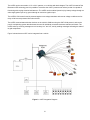


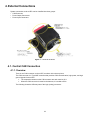


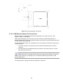


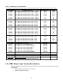

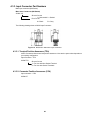


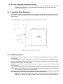

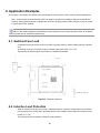


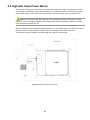


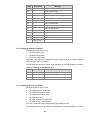


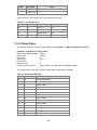
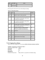


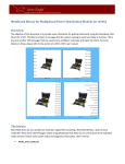


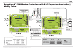


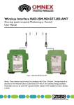


![Hospice Technical Questions & Answers [PDF 114 KB]](http://vs1.manualzilla.com/store/data/005731144_1-513883a519d0031f5bbd9acf18f18865-150x150.png)