1
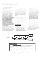
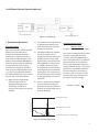
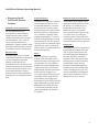
Saint-Gobain Crystals Scintillation Detector Operating Manual > Handling and care > Installation > Troubleshooting Contents Handling and Care of Crystal Scintillation Detectors Unpacking Instructions................................................................................................1 Storage and Thermal Shock........................................................................................1 Crystal Hydration...........................................................................................................1 UV Exposure....................................................................................................................1 Light Leaks.......................................................................................................................1 Beryllium Windows.......................................................................................................2 Cleaning and Decontamination.................................................................................2 Installation Procedures Packaged Crystal Scintillator Detectors...................................................................2 Single Integrally Mounted or Demountable Crystals/PMT Detectors......... 2,3 X-ray Probes....................................................................................................................4 Photodiode Scintillation Detectors...........................................................................4 Multiple PMT Detectors...............................................................................................5 Electronic Adjustments Voltage Divider Adjustment Potentiometers.........................................................6 Balancing Procedure.....................................................................................................6 Ground Loop....................................................................................................................6 Performance Testing .............................................................................................................. 7 Diagnosing Crystal Scintillation Detector Problems ...................................................... 8 Troubleshooting Tips ........................................................................................................ 9,10 Physical Properties of Common Inorganic Scintillators...............................................11 Warranty................................................................................................................................12 Important Note on the Safe Handling of NaI(Tl) Crystal Material A sodium iodide [NaI(Tl)] crystal is activated by the addition of a very low concentration of thallium iodide (TlI). We asked our law firm to give us an opinion whether this product should be treated as a hazardous material for labeling purposes. A quote from their response dated November 29, 1984, follows. “We have examined the Dangerous Goods Regulations effective 1 January 1985, as promulgated by the International Air Transport Association and the Hazardous Materials Regulations promulgated by the U.S. Department of Transportation, Research and Special Programs Administration, Materials Transportation Bureau. It is our opinion, based upon our review of these materials, that your products containing sodium iodide crystals with traces of thallium iodide are not considered hazardous or poisonous.” However, thallium iodide as a pure chemical is toxic. One of our suppliers tells us that amounts of more than 1 gram per person can cause death. Another supplier states the LD-50 is 28 milligrams per kilogram body weight. On a more practical basis, there is the personnel hazard that exists from a damaged, and possibly leaking, crystal container. A thallium-activated sodium iodide crystal on average is 99.8% sodium iodide and 0.2% thallium iodide. The weight of a 2-inch diameter by 0.25 inch thick NaI(Tl) crystal is 47.24 grams including 0.094 grams of TlI. Casual contact with the small fraction of this material which might leak from a damaged container is not a serious hazard. If a container is damaged, handle with disposable rubber gloves. Dispose of the detector materials according to local and federal regulations at an approved site. If you are unable to do so, please call Saint-Gobain Crystal’s customer service department for a Return Materials Authorization (RMA) number so the damaged detector can be returned to us for proper disposal. Scintillation Detector Operating Manual > Handling and Care of Crystal Scintillation Detectors Unpacking Instructions – CAUTION . . . DO NOT OPEN PACKAGE UNTIL DETECTOR REACHES ROOM TEMPERATURE! If the detector package comes into the laboratory from a truck or warehouse where the temperature differs by 5°C (10°F) or more from that of the laboratory, allow the package to reach room temperature before opening. This will prevent fracturing the crystal from thermal shock. A good practice is to leave the package in the laboratory overnight before opening. If damage to the shipping carton is apparent, ask that the carrier’s agent be present when the detector is unpacked, or otherwise document the damage. Saint-Gobain Crystals cannot replace a detector damaged in shipment without this damage report. Inspect the detector for mechanical damage, scratches, dents, etc. Check any mechanical or thermal shock indicators that may be packed with the detector. Storage and Thermal Shock – NEVER STORE THE DETECTOR NEAR A HEATING ELEMENT, SUN-WARMED SURFACE, RADIATOR OR AIR CONDITIONER! Unless specifically designed to withstand other conditions, Saint-Gobain Crystals detectors are intended for use in a normal laboratory environment. They will operate reliably between 4°C and 43°C (40°F and 110°F), provided the rate of temperature change does not exceed 8°C (15°F) per hour. Crystal Hydration – Some crystals are hygroscopic (see chart on page 12) which means they are easily damaged when exposed to moisture in air at normal humidity levels. Some bare crystals can dissolve in room humidity. The hermetic seals used in these assemblies must be protected at all times. For this reason, avoid using strong organic solvents which may dissolve or soften epoxy seals. Similarly, never expose the detector to mechanical shock that may crack or chip the seals. In NaI(Tl) crystals, hydration first appears as yellow/green spots on the surface and later as a distinct tint to the crystal. Because the hydration is yellow/green, it is an excellent absorber of blue scintillation light and will significantly degrade light output and thereby resolution. Except at low energies, counting efficiency is not normally impaired if the proper electronic adjustments are made. In CsI(Na), hydration first deactivates the surface of the crystal. Damage produced by a small amount of hydration is not visible to the eye and does not affect resolution at high energies. At low energies, the resolution and efficiency of the detector are drastically impaired — as much as 40% up to 120 keV for a 1mm hydrated layer. In the BrilLanCe® scintillators [LaCl3(Ce) and LaBr3(Ce)] , discoloration may not be noticeable, but the detector performance deteriorates. Other scintillators that are not hygroscopic are also affected by excessive moisture. CsI(pure), CsI(Tl), and BaF2 crystal surfaces are easily damaged by drops of moisture or excessive condensation. In general, deterioration of energy resolution or of the absolute efficiency is an indicator of detector degradation. UV Exposure – Ultraviolet radiation in sunlight or fluorescent lighting can produce discoloration and phosphorescence in scintillation crystals. The coloration produced by UV radiation appears in the bulk of the crystal rather than the surface and is most noticeable in large crystals. For this reason, open window detectors or unpackaged crystals should be stored in darkness when not in use. In NaI(Tl), the damage usually appears as a slightly muddy brown color and produces a loss of resolution. BGO is also very sensitive and its performance deteriorates quickly. BGO and NaI(Tl) should be protected from UV and should be stored in the dark. Counting efficiency is not generally impaired, though pulse height decreases and resolution deteriorates. Light Leaks – A light leak into the photomultiplier tube (PMT) assembly will cause continuous emission of photoelectrons from the PMT’s photocathode when high voltage is on. In the D.C. current mode of operation, this will result in an increased signal that can be detected by switching the room lights on and off. In the pulse mode of operation, light leaks can be detected by looking at the system’s output with an oscilloscope. Set the sweep speed at approximately 5 µsec/cm and trigger on the smallest possible pulse (high vertical gain, but above the electronic noise level). Switch the room lights 1 Scintillation Detector Operating Manual on and off again, looking for changes in the trigger rate. Beryllium Windows – As with any thin radiation entrance window, take care not to puncture or stress the beryllium windows used in many X-ray and low-energy detectors. Also, avoid touching the window surface as the mild acid from oil in fingerprints can etch through the beryllium causing a loss of hermeticity. Cleaning and Decontamination – We recommend using a mild detergent solution made with water for cleaning exterior surfaces of your detector. A soft sponge or lint-free cloth can be used to wipe the detector (a cotton swab is useful for cleaning wells). The cloth or swab may be moistened with methyl alcohol to remove contamination or dirt from metallic or glass surfaces. A quick temporary package may be made by coupling the crystal to a light-shielded PMT and then wrapping the combined unit with two or more wraps of black tape from crystal container to tube, overlapping both. Note: All parts of the PMT glass bulb must be in the dark. Optical couplings to the PMT may be made with silicone optical grease, silicone rubber pads, or other optically transparent compounds. The coupling should be as thin as is practical and free of excess compound for optimum resolution. The PMT also should be surrounded by one or two wraps of conetic foil or other magnetic shielding. A more permanent package can be made by using a mu-metal light shield over the PMT. To operate the PMTs, you will need a compatible plug-on voltage divider or voltage divider/preamplifier and appropriate connecting cables. Note: Some 14-pin PMTs are only 8-stage and require a special voltage divider. Refer to “Basic Connections” for further installation instructions. > Installing Single Integrally Mounted or Demountable Crystal/PMT Detector Assemblies Saint-Gobain Crystals supplies a number of different detector configurations that come with a single PMT. The scintillator and PMT can be mounted in the same container or the detector assembly can feature separate, demountable scintillator and PMT housings. On request we can integrate hard-wired voltage dividers or voltage divider/preamps within these detectors. However, most detectors terminate in a phenolic PMT base with 12 or 14 connecting pins. If the detector is not hermetically sealed (e.g., some BGO and BaF2), care should be taken that no liquid enters into the interior volume where it can wet the scintillator surface or the reflector material. To install these detectors, you will need a compatible plug-on voltage divider or voltage divider/preamplifier and appropriate connecting cables. Avoid exposing the detector to acetone as it may cause chemical damage to the hermetic seals and, upon evaporation, thermal shock to the detector. 1) Unless you have a detector with integrated voltage divider or voltage divider/preamplifier, press a plug-on voltage divider onto the PMT base. (Be sure to align the keyway before pressing.) Basic Connections – Pictured are various standard packaged crystals and single crystal/PMT detector assemblies. > Installing Packaged Crystal Scintillator Detectors A packaged crystal scintillator is sealed by itself in a lightweight aluminum can with a single optical window. The photomultiplier tube (PMT) is normally supplied separately. CAUTION: DO NOT EXPOSE CRYSTAL TO ULTRAVIOLET RADIATION FROM FLUORESCENT LAMPS OR SUNLIGHT. Saint-Gobain can also provide voltage divider and voltage divider/preamplifier assemblies. 2) Using RG-59/U or equivalent coaxial cable, connect the positive high voltage supply (800 to 1300 volts) to the SHV (or MHV) connector as shown in Figure 1 or Figure 2. The connector is marked “HV.” The “SHV” can be recognized by its overall length or the “MHV” by the inner Teflon® insulation extending higher up than that 2 Scintillation Detector Operating Manual in the signal connector. See the Quality Assurance (Q.A.) Sheet supplied with your detector for a typical HV value. 3) Connect the system electronics to the BNC signal connector (marked “S”) using RG-58/U or RG-59/U coaxial cable again as shown in Figure 1 or Figure 2. (Cable length of less than 10 feet is recommended.) Note: If you are using a voltage divider/preamplifier, no external preamp is required in your system electronics (Figure 2). However, you will need a separate power supply to provide negative (-)24 volts through the 9-pin connector’s pin 6 and ground (common) on pin 1. unit’s rear panel. If your amplifier does not have this capability, you can use an appropriate, laboratory D.C. power supply. Many NIM-Bin mounted amplifiers have this voltage available in a matching 9-pin connector on the Negative-going Signal— Preamp Amplifier Scintillator plus PMT & Volt Divider HV Power Supply Single or Multi-Channel Analyzer Readout Figure 1 Positive-going Signal— Amplifier Scintillator plus PMT & VD/Preamp HV Power Supply Single or Multi-Channel Analyzer Readout Figure 2 -24V Supply High Voltage – caution: The voltages applied to and the currents used with photomultiplier tubes are hazardous. Detectors must be operated at positive high voltage unless specially modified for negative high voltage operation. A detector’s outer metallic housing serves as a light and electrostatic shield. For proper operation and as a necessary safety precaution, the metallic housing should be attached to a good or solid ground connection. If the PMT is operated at negative (-) high voltage, an additional electrostatic shield is attached to the PMT to prevent electrostatic degradation of the glass bulb. 3 Scintillation Detector Operating Manual > Installing X-ray Probes Saint-Gobain Crystals’ X-ray probes consist of a packaged crystal scintillator X-ray detector mounted behind a collimator in a common housing with an integrally mounted photomultiplier tube and voltage divider. The probe is usually purchased with an integrated FET preamp. Each probe comes with 12 ft. long cables hard-wired to the voltage divider or preamp and terminating in appropriate connectors. Basic Connections – 1) Connect the high voltage connector to any commercial power supply designed to provide positive high voltage to photomultiplier tubes. The cable is marked “HV.” The connector is usually “SHV” and can be recognized by its overall length. If it is “MHV”, the inner Teflon® insulator is similar to but extends higher up than that in the signal connector. 2) Adjust the voltage to yield the desired amplification. The Q.A. Sheet will list a safe operating voltage. Generally, any voltage between 700 and 1400 volts will produce satisfactory performance. 1500 volts is the maximum voltage that a typical PMT can take without damage. Some PMTs can handle higher voltage. If in doubt, check the PMT manufac-turer’s data sheet for their specifications. 3) Connect the BNC signal connector to the system preamplifier’s input, as shown in Figure 1 on page 3, or directly to the system amplifier’s input for the probe packaged with an FET preamp (Figure 2). Note: no external preamp is required in your system electronics when using a the probe packaged with an FET preamp. 4) If you are using the probe/ preamp detector package, supply negative (-)24 volts to the FET preamp through pin 6 and ground (common) through pin 1 of the 9-pin connector. Many NIM-Bin mounted amplifiers have this voltage available in a matching 9-pin connector on the unit’s rear panel. If your amplifier does not have this capability, you can use an appropriate, laboratory D.C. power supply. >Installing Photodiode Scintillation Detectors Cable Output – If cables are provided with your photodiode detectors: 1) Connect the cable marked “signal” to the amplifier; 2) Connect the cable marked “B” to the low voltage(+24V) power supply. The cable shield is grounded. Connector Output – If your detector has only connectors at the back of the detector housing: 1) Using coaxial cable, connect the “signal” connector marked “S” to the amplifier; 2) Supply the connector marked “B” with +24V bias voltage; 3) Supply the dual pin connector usually marked +/-12V with +/- 12V power. 4 Scintillation Detector Operating Manual > Installing Multiple PMT Detector Assemblies In multiple PMT detector assemblies, the photomultiplier tubes are demountable by removing the socket head screws on the flange of each PMT housing. The tube may be lifted from its optical window by gently pressing and sliding or twisting the housing. Caution: Make sure high voltage is disconnected before disassembling detector. Silicone optical grease forms the optical coupling between PMT and window. PMTs should not be removed unless absolutely necessary because recoupling and alignment is sometimes difficult. Most multiple PMT detectors have PMTs that terminate in a phenolic base with connecting pins. To operate these detectors you usually will need a plug-on voltage divider for each PMT. Use 12-pin voltage dividers with 12-pin PMT bases (1.5” PMTs) and 14-pin voltage dividers with 14pin PMTs (2”, 3”, 3.5” and 5”). Other plug-ons are available for other types of PMT bases. Note: Some 14-pin PMTs are only 8-stage and require an appropriate 14-pin plug-on voltage divider. When two or more PMTs are used on one detector, their signals must be summed into one signal input. Do this by connecting the plug-on voltage dividers in parallel — signal (S) to signal (S) and high voltage (HV) to high voltage (HV). Basic Connections – 1) Press a plug-on unit onto each PMT base. 2) Using RG-58/U or RG-59/U coaxial cable, connect the positive high voltage supply (800 to 1300 volts) to the high voltage (HV) connector of each voltage divider or the network. An “SHV” connector can be recognized by the overall length or an “MHV” by the inner Teflon® insulation extending higher up than that in the signal connector. T-connectors (or a fan-out box) simplify making parallel connections (Figure 3). See the Q.A. sheet supplied with your detector for a typical HV value. 3) Connect the preamplifier from the system electronics to the signal connectors (S) using RG58/U or RG-59/U coaxial cable (and T-connectors or fan-out box, if required) again as shown in Figure 3. Figure 2 shows a block diagram of a complete system. Standard plug-on voltage dividers use SHV connectors for high voltage and BNC connectors for signal. HV Power Supply Figure 3 Divider #1 Divider #2 Divider #3 Preamp Positive High Voltage – Caution: probes AND detectors must be operated at positive high voltage unless specially modified for negative high voltage operation. The detector’s outer metallic housing serves as a light and electrostatic shield. It is good practice to ground the metallic housing. Note: For voltage divider and preamplifier schematics and design information, please request our Voltage Divider Design Considerations. 5 Scintillation Detector Operating Manual > Electronic Adjustments Adjustment Potentiometers – The one turn gain balance potentiometer (marked “G”) may be used as a variable gain adjustment to balance pulse heights from two or more phototubes. Turning it fully clockwise yields maximum gain. Further gain adjustment may be accomplished by changing the high voltage although extreme settings may lead to low level noise or loss in resolution. 1000 volts D.C. is usually optimum for 2”, 3”, 3.5” and 5” PMTs, and 900 volts for 1.5” PMTs. The one turn focus potentiometer (marked “F”) on 14-pin voltage dividers and 14-pin voltage divider/ preamplifiers should be adjusted to yield the best resolution (not necessarily highest pulse height). This may be accomplished by taking four spectra at quarter turn intervals on the pot and measuring the resolution of a suitable gamma-ray peak (normally the 137Cs 662 keV gamma line) at each setting. Choose the best setting by interpolation. Balancing Procedure – For detectors with more than one PMT, the signals can be summed into a single output. Operation is then much like that of a single tube. First, each tube gain must be adjusted so that its output pulse height is identical to the other tubes on the assembly. This adjustment is called BALANCING. 1) Connect the signal cable to the counting electronics (all PMTs in parallel). For best results, balancing should be done with a multichannel analyzer. The balancing is done with all cables in place in parallel so that changes in pulse height due to cable capacitance variation is eliminated. 2) Place a source (typically 5µCi of 137Cs) on the axis of the detector at a distance of about twice the diameter of the detector. The count rate needs to be appreciably higher than background rates, but not so high as to cause electronic pile-up. A few thousand counts per second is usually adequate. 3) Set the high voltage power supply to the required voltage. Turn all voltage divider gain balance potentiometers fully clockwise to maximum gain. Examine the output of each PMT separately with a pulse height analyzer (collect a spectrum). To sample each tube, leave the HV on or connected only to the tube being checked. The signal cables should be connected to all the tubes at all times. This prevents impedance changes and, therefore, gain changes. 4) Compare the channel number or voltage (pulse) height of the gamma line from each spectrum. Leave the PMT with the lowest gain alone and adjust (reduce) the gain of the other tubes to match. Do this by incrementally turning the voltage divider gain balance potentiometer counter clockwise, collecting a spectrum, and checking the channel number for each remaining PMT in turn until their gains match that of the one with the original lowest pulse height. 5) Reconnect the HV wiring harness and apply voltage to all tubes. The tube array is now balanced at the supply voltage used in this procedure. Operation at another voltage may necessitate some rebalancing of the array, since individual tube gains do not track uniformly with increasing and decreasing voltages. Ground Loop – The block diagram (Figure 4) shows the normal ground configuration in a system with a sensor or probe at some distance from the readout electronics: 1) The signal ground is connected to the earth ground at the readout end of the system only. The HV, amplifier and MCA grounds are all connected through the power plugs to a local ground. See Figure 4. 2) At the sensor end, the case is connected to the local ground, but the signal ground is kept isolated from the local ground. This eliminates a ground loop geometry that can lead to the pickup of electromagnetic waves. These waves show up as noise. The ground loop is formed when the signal ground at the voltage divider (or PMT) is connected to the case ground. The signal ground is connected at both ends to the earth ground and this completes the loop through the earth ground. For those applications where this is not a problem, the case ground can be connected to an unused pin, #12 in the 14 pin base, or to the photocathode which is at ground in the +HV systems. 6 Scintillation Detector Operating Manual NaI(Tl) Crystal Voltage Divider HV PMT Preamp Amplifier MCA case ground only case and signal ground Figure 4. Ground Loop > Performance Resolution Resolution Testing – After your detector has been installed properly, the resolution can be checked. A scintillation detector’s performance is typically stated as a value of pulse height resolution, full width at half maximum (FWHM) for a particular gamma-ray peak. Although any gamma emission line may be used, the most frequently specified value is for the 662 keV gamma ray of 137 Cs. (For an X-ray probe or detector, the most specified value is the 5.9 keV X-ray of 55Fe). Proceed as follows: 1) Apply a positive high voltage (check our Q.A. sheet for appropriate voltage) to the phototubes, and allow 15 minutes to an hour for the gain to stabilize. 2) Set the time constant of the main or spectroscopy amplifier to 4 times the decay time (see chart on page 12) or greater. 3) Uniformly irradiate the entrance face of the crystal with an appropriate radiation source (0.1 to 10.0 microcuries), but avoid high counting rates greater than about 8000 cps. If pulse pile-up or amplifier saturation occurs, the resolution value will not be a meaningful measure of detector performance. The “dead time” of the multichannel analyzer should be kept below 10%, less than 5% if possible. 4) Collect a spectrum and calculate the resolution by dividing the peak channel into the number of channels at the full width at half of the peak height. Calculating the Resolution – Channel C - Channel A Resolution = X 100% Channel B There must be adequate counts under the peak to yield good statistical accuracy--normally 5,000 counts or more in the peak channel is sufficient. Resolution values are not constant with energy. A detector having 7.5% energy resolution for the 137Cs 662 keV gamma line may exhibit resolutions of 15% at 122 keV (57Co) and 6% at 1172 keV (60Co). As a rule of thumb, the resolution varies with one over the square root of the energy. Resolution = constant x 1 √E Counts per Channel Maximum Counts Half Maximum Counts Channel ABC 0 Counts (background subtracted) Figure 5. Calculating Resolution 7 Scintillation Detector Operating Manual > Diagnosing Crystal Scintillation Detector Problems PHR Differs from Report Values – You may experience minor discrepancies in measured pulse height resolution (PHR) and the numbers reported on the test sheet for each detector. This is normal and is caused by differences in phototubes. However, should a major discrepancy become evident, contact Saint-Gobain Crystals immediately. Moisture Leaks – For hygroscopic crystals, moisture leaks produce hydration on the crystal surface and degrade resolution. Hydrate usually appears as a discoloration on or in the crystal. The effect on performance can sometimes be similar to that of a fracture. It can be distinguished from a fracture, however, because the performance degrades over an extended period of time. Crystal Fracturing – Extraneous Peaks in the Spectrum – Sometimes, if a crack is not excessive and has proper orientation, it will not impair performance. However, fractured crystals usually produce asymmetrical peaks and may exhibit multiple peaks for a single gamma line. A fracture is normally stable and will not propagate. If a crack is noticed, check performance and call the factory. Note: The thin, cleaved crystals used in X-ray detectors often exhibit cleave marks. These marks look like cracks, but have no effect on detector performance. If unidentified peaks appear in your spectrum in counting times of under 60 minutes, it is unlikely they are produced by the detector. If the width of the peaks are narrower than a gamma peak of equal energy, it is certain to be a result of your electronic system. If the peak is the same width as a gamma line, look for unshielded sources near the detector. Noise – Noise in a spectrum is generally defined as the extraneous events counted near the zero energy end of the spectrum. It is nearly always a product of the photomultiplier due to spontaneous emission from the photocathode and other phenomena within the tube. It appears as a near-exponentially decreasing curve extending into the spectrum that often obscures low energy peaks. Acceptable noise level varies with the type of phototube used, but would probably be considered excessive if it extended far enough into the spectrum to obscure 15 to 20 keV X-ray peaks. Background – Saint-Gobain crystals are grown from highly purified, low potassium salts and, in a given circumstances, will have low background. Background from the detector is usually not significant unless one hour or more counting times are taken in heavily shielded (4 to 6 inches of lead) chambers. Background spectra are complex and are the result of many sources, including cosmic rays and natural radioactivity. If background appears to be a problem, call SaintGobain Crystals for assistance. 8 ❚ Troubleshooting Crystal Scintillation Detectors ❚ problem / Probable Cause corrective procedure No Output 1. No radioactive source. 1. Place radioactive source near detector and check response. 2. PMT voltage is off, too high, too low or wrong polarity. 2. Refer to appropriate instrument manual or instruction sheet. Check current capacity of HV supply. 3. Defective cables or connectors. 3. Substitute known good cables. Service may be indicated contact Saint-Gobain Crystals for instructions. 4. Short circuit or loss of vacuum in photomultiplier tube(s). 5. Wrong hook-up. 4. Substitute known good tubes if demountable. Service may be indicated - contact Saint-Gobain Crystals for instructions. 5. See Basic Connections section of this manual. Resolution does not meet specifications 1. Radioactive source type, location, or activity has changed. 2. Tubes are not properly balanced. 1. Check radioactive source type, location and activity. 2. Refer to balancing procedure. See Q.A sheet supplied with your detector for typical values. 4. Improper electronic pulse shape between detector and analyzer. 3. Refer to appropriate instrument manual or instruction sheets. (NOTE: Channel zero must correspond to zero pulse height or zero energy, or appropriate corrections must be made.) 5. Focus potentiometer of tube(s) not adjusted correctly. 4. Refer to appropriate instrument manual or instruction sheets and check pulse polarity. 6. Defective interface between crystal and photomultiplier tube. 5. Adjust for minimum pulse height resolution. 3. Analyzer/Electronics not properly zeroed. 7. Defective tube or improper operating voltage. 8. Photomultiplier tube or electronic drift during measurements. 6. Clean face plate of the detector and the tube and apply fresh optical coupling compound. 7. Refer to appropriate instrument manual. Service may be indicated. Contact Saint-Gobain Crystals for instructions. 9. Light leak in assembly. 8. Allow longer warm-up. Service may be indicated. Contact Saint-Gobain Crystals for instructions. 10. Cracked crystal. 9. Use black tape or black felt for emergency repair. 11. Hydrated crystal. 10. Detector may function in an acceptable manner. If not, contact Saint-Gobain Crystals for instructions. 12. UV damage to crystal. 13. Various scintillators have different decay constants. 11. Contact Saint-Gobain Crystals for instructions. 12. Contact Saint-Gobain Crystals for instructions. 13. Adjust amplifier time constants (normally 4 times decay constant of scintillator). Check Q.A. Report of scintillator in question. 9 ❚ Troubleshooting Crystal Scintillation Detectors ❚ problem / Probable Cause corrective procedure Low Count Rate 1. Improper electronic settings (peak not in window). 2. Excessive dead time in electronics or pulse height analyzer. 1. a) Refer to appropriate instrument manual. Check lower level discriminator (LLD), upper level discriminator and signal output by scope. b) Improper lower level discriminator setting may result in low count rate. If the LLD is set properly, refer to resolution troubleshooting. 2. Refer to appropriate instrument manual. 3. Light leak causing excessive dead time. 3. Use black tape or black felt for emergencies. 4. Cracked crystal. 4. This will probably show up as poor resolution too. Refer to resolution troubleshooting. 5. Intermittent high voltage supply. 5. Should also show up as poor resolution or drifting peak. Refer to appropriate instrument manual. High Count Rate 1. Lower level discriminator (or threshold) set too low. Probably below the detector noise level. 1. Reset LLD (or threshold) after checking appropriate instrument manual. 2. Tube noise too high - possible light leak. 2. Check for light leak. Use black tape or black felt for emergency repair. 3. Light leak causing excessive dead time. 3. Use black tape or black felt for emergencies. 4. Analyzer threshold too low. 5. HV breakdown in cable(s) or voltage divider(s). 6. Line noise/interference. 7. Excessive background radiation. Inability to Balance Tube(s) 4. Check appropriate manual. Check D. C. levels. 5. Service may be indicated - contact us for instructions. 6. Refer to appropriate instruction manual. 7. Shield detector - check for other sources - move to quiet location. 1. Replacement PMT not matched to rest of set. 1. Contact Saint-Gobain Crystals if replacement PMT cannot be matched. 2. Improper operating voltage. 2. Refer to appropriate instrument manual. 3. Tube(s) have aged or deteriorated. 3. Service may be indicated - contact us for instructions. Extraneous Peaks in Spectrum 1. Electronic overloads at preamplifier (peaks are narrower than gamma lines). 2. Background radiation (all building materials contain trace amounts of natural uranium, thorium and potassium). 1. Refer to appropriate instrument manual. 2. a) Be sure detector and surroundings are “clean.” See instructions in “Handling and Care” section of this manual. b) For optimum low background, shield the detector. Note: For voltage divider and preamplifier schematics and design information, please request our Voltage Divider Design Considerations. 10 41 32 12 - 15 19 54 8 - 10 8 2 1.8 CsI(Na) PreLude™420 Lu1.8Y.2SiO5(Ce) CdWO4 CaF2(Eu) CsI(Tl) BGO YAG(Ce) Y3Al5O12(Ce) CsI(pure) ZnS(Ag) ~50 10 3 49 BrilLanCe™350 LaCl3(Ce) BaF2 4-6 38 Polyscin®NaI(Tl) 130 16 15 20 45 50 30 - 50 75 85 70 - 90 100 100 38 NaI(Tl) 165 63 BrilLanCe™380 LaBr3(Ce) Scintillator Light yield (photons/keV) Light ouput (%) of NaI(Tl) bialkali pmt -0.6 -1.1 0 -0.3 -- -1.2 0.01 -0.33 -0.1 -0.28 -0.05 0.7 -0.3 -0.3 0 Temperature coefficient of light output (%/C) 25°C to 50°C 110 630 0.6 - 0.8 16 70 300 1000 940 14000 41 630 28 250 250 16 1/e Decay time (ns) (10-3µs) 450 310 220 (195) 315 550 480 550 435 475 420 420 350 415 415 380 Wavelength of maximum emission γm (nm) 2.36 1.50 1.54 1.95 1.82 2.15 1.79 1.47 ~2.3 1.81 1.84 ~1.9 1.85 1.85 ~1.9 Refractive index at γm -- 1.9 1.9 2 2 1 2 2.9 1 1.1 2 2.3 2.5 2.5 1.8 Thickness to stop 50% of 662 keV photons (cm) -- <111> <111> none none none none <111> <010> none none <100> none <100> <100> Cleavage plane -- 3 3 2 8.5 5 2 4 4 - 4.5 2 2 2 Hardness (Mho) 4.09 4.88 4.88 4.51 4.55 7.13 4.51 3.18 7.9 7.1 4.51 3.85 3.67 3.67 5.08 Density g/cm3 no slightly slightly slightly no no slightly no no no yes yes yes yes yes Hygroscopic Multicrystal, 15µ stops 5.5 MeV α (n detection with 6Li) Slow component Fast component (subnanosecond) High Z, fast emission β-ray, X-ray counting, electron microscopy High Z, compact detector, low afterglow High Z, rugged, good match to photodiodes Low Z, α & β detection High Z, low afterglow, for use with photodioides Bright, high Z, fast, dense, background from 176Lu activity High Z, rugged General purpose, excellent energy resolution Polycrystalline NaI(Tl), for extra strength General purpose, good energy resolution General purpose, best energy resolution, rate of change of light output w/ temperature is small Comments The data presented are believed to be correct but are not guaranteed to be so. -- 18.4 18.4 54 ~80 7 54 19.5 10.2 -- 54 11 47.4 47.4 8 Thermal expansion (°/C) x 10-6 Physical Properties of Common Inorganic Scintillators The Saint-Gobain Crystals Warranty Inorganic Scintillation Detectors Saint-Gobain Crystals will repair or replace, at no charge, any detector which fails within a period of two years* from date of shipment as a result of faulty construction or failure of the hermetic seal(s). This warranty does not apply to any detector which fails as a result of rough handling, mishandling, being dropped, being submerged in water or being exposed to a non-laboratory environment. A normal laboratory environment is defined as air at normal pressure and any humidity, at a temperature between +40°F and +110°F (+4°C to +43°C) which temperature does not change at a rate greater than 15°F(8°C) per hour and which does not heat or cool any region of the detector such as to produce a temperature gradient of greater than 5°F(3°C) across the affected region. Detector assemblies designed for use in specific applications where severe environmental conditions may be encountered carry a specific warranty. Please contact sales/customer service for further explanation of warranties. Photomultipliers For photomultipliers (PMTs), Saint-Gobain Crystals passes on to the customer the PMT manufacturer’s warranty, which in most cases is one year. General This warranty applies only to the original purchaser of the detector and only to product with serial numbers still legible. This warranty does not apply to any detector whose performance fails as a result of misuse, mishandling, abuse, accident, physical damage, improper installation, exposure to vacuum, or submersion in water. This warranty does not apply if the product has been modified or altered without Saint-Gobain Crystals’ express approval. Saint-Gobain Crystals’ obligation hereunder shall be limited to the repair or replacement, at our option, of any detector or any part thereof which, upon receipt and examination, proves to have been defective within the specified warranty period. Saint-Gobain Crystals is not responsible for damages of any kind including incidental or consequential damages. To the extent permitted by law, this warranty is in lieu of all other warranties, express or implied, and constitutes the fulfillment of Saint-Gobain Crystals obligations to the purchaser. Instructions for Returning Product to Saint-Gobain Crystals A claim against the Saint-Gobain Crystals warranty must be made by the original purchaser within the warranty period. The purchaser must obtain a Return Materials Authorization (RMA) number from Saint-Gobain Crystals’ sales/customer service organization (440/834-5600) prior to shipment. The RMA number must be referenced on the packing list and other documentation. All detectors being returned for warranty repair should be adequately packaged; use of original Saint-Gobain Crystals shipping material and container will help assure that no damage occurs in transit or storage. Product claimed to be defective or non-conforming must be returned to Saint-Gobain Crystals freight prepaid by the purchaser with a statement identifying the reason(s) for the return, the Saint-Gobain Crystals part number and serial number. Please ship against a return purchase order rather than a debit memo. Product returned to Saint-Gobain Crystals that is found to be in good working order or damaged for causes not covered by this warranty will be subject to a service charge. Upon completion of repairs, detectors will be returned to the purchaser freight prepaid. *one year for BrilLanCe® series detectors The information in this manual is believed to be accurate but is not guaranteed to be so. Nothing herein shall be construed as suggesting the use of our product in violation of any laws, regulations, or rights of third parties. Buyer should evaluate suitability and safety of product for buyer’s use. We cannot assume liability for results that buyer obtains with our products since conditions of use are not under our control. 12 These other inorganic scintillator technical notes are available upon request and on our web site. USA Saint-Gobain Crystals 17900 Great Lakes Parkway Hiram, OH 44234 Tel: (440) 834-5600 Fax: (440) 834-7680 Europe Saint-Gobain Crystals 104 Route de Larchant BP 521 77794 Nemours Cedex, France Tel: 33 (1) 64 45 10 10 Fax: 33 (1) 64 45 10 01 P.O. Box 3093 3760 DB Soest The Netherlands Tel: 31 35 60 29 700 Fax: 31 35 60 29 214 Japan Efficiency Calculations for Selected Scintillators FWHM Analysis for Arbitrary Peak The Change of Gamma Equivalent Energy with Temperature for Scintillation Detector Assemblies Measuring Performance of Anti-Compton Shield Measuring Radiation: An Introductory Discussion Performance of NaI(Tl) Scintillation Pulse Height Shift with Detector Counting Rate Radioisotopes Chart Simulating Scintillation Pulses with an LED Light Pulser Voltage Divider Design Considerations Saint-Gobain KK, Crystals Division 3-7, Kojimachi, Chiyoda-ku, Tokyo 102-0083 Japan Tel: 81 (0) 3 3263 0559 Fax: 81 (0) 3 5212 2196 China Saint-Gobain (China) Investment Co, Ltd 15-01 CITIC Building 19 Jianguomenwai Ave. Beijing 100004 China Tel: 86 (0) 10 6513 0311 Fax: 86 (0) 10 6512 9843 Visit our web site: www.crystals.saint-gobain.com to view our Library (data sheets, technical literature, news releases, current events, etcetera) India Saint-Gobain Crystals and Detectors Sy. No. 171/2, Maruthi Industrial Estate Hoody Rajapalya, Whitefield Main Road Bangalore 560048 India Tel: 91 80 42468989 Fax: 91 80 28416501 BrilLanCe, PreLude and “It’s what’s Inside that Counts” are registered trademarks of Saint-Gobain Ceramics & Plastics, Inc. Patents pending on BrilLanCe materials. www.crystals.saint-gobain.com The data presented are believed to be correct but are not guaranteed to be so. ©2004-2014 Saint-Gobain Ceramics & Plastics, Inc. All rights reserved. (06-14)