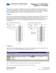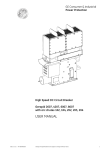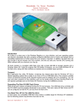
1
Installation Instructions 0100234-01A
InView Communication Modules
Catalog Number: 2706-PENET1-SC
2
InView Communications Modules Installation Instructions
About This Publication
This publication shows how to connect the InView communication module to the InView display.
Important User Information
Solid state equipment has operational characteristics differing from those of electromechanical
equipment. Because of this difference, and also because of the wide variety of uses for solid state
equipment, all persons responsible for applying this equipment must satisfy themselves that each intended
application of this equipment is acceptable.
In no event will Spectrum Controls, Inc. be responsible or liable for indirect or consequential damages
resulting from the use or application of this equipment.
The examples and diagrams in this manual are included solely for illustrative purposes. Because of the
many variables and requirements associated with any particular installation, Spectrum Controls, Inc.
cannot assume responsibility or liability for actual use based on the examples and diagrams.
No patent liability is assumed by Spectrum Controls, Inc. with respect to use of information, circuits,
equipment, or software described in this manual.
Reproduction of the contents of this manual, in whole or in part, without written permission of Spectrum
Controls, Inc., is prohibited.
Throughout this manual, when necessary, we use notes to make you aware of safety considerations.
WARNING
WARNING
IMPORTANT
ATTENTION
Identifies information about practices or circumstances that can cause
an explosion in a hazardous environment, which may lead to personal
injury or death, property damage, or economic loss.
Identifies information that is critical for successful application and
understanding of the product.
Identifies information about practices or circumstances that can lead to
personal injury or death, property damage, or economic loss. Attentions
help you to identify a hazard, avoid a hazard, and recognize the
consequences.
SHOCK HAZARD
Labels may be on or inside the equipment, for example, a drive or
motor, to alert people that dangerous voltage may be present.
BURN HAZARD
Labels may be on or inside the equipment, for example, a drive or
motor, to alert people that surfaces may reach high temperatures.
Installation Instructions 0100234-01A
InView Communications Modules Installation Instructions
3
Table of Contents
ABOUT THIS PUBLICATION ..................................................................................................................................... 2
IMPORTANT USER INFORMATION ......................................................................................................................... 2
OVERVIEW ............................................................................................................................................................. 4
WHY USE THE INVIEW ETHERNET TCP/IP MODULE? .............................................................................................. 4
DESCRIPTION OF THE INVIEW ETHERNET TCP/IP MODULE .................................................................................... 4
WIRING THE ETHERNET TCP/IP MODULE TO THE INVIEW DISPLAY ........................................................................ 5
MOUNTING MODULE TO THE 2706-P42-SC AND 2706-P44-SC DISPLAYS................................................................ 6
MOUNTING MODULE TO THE 2706-P72-SC AND 2706-P74-SC DISPLAYS................................................................ 6
SETTING THE IP ADDRESS ....................................................................................................................................... 6
GATEWAY ADDRESS AND SUBNET MASK SETUP .................................................................................................... 9
ADDITIONAL RESOURCES ..................................................................................................................................... 10
GETTING TECHNICAL ASSISTANCE ........................................................................................................................ 10
Installation Instructions 0100234-01A
4
InView Communications Modules Installation Instructions
Overview
A serial server is an electronic device that provides Ethernet connections for signs and other serial devices
by converting serial data to, and from, Ethernet format.
A serial server is an economical way to add InView Displays to an existing LAN. Instead of running
separate cabling to create a sign network, InView displays can be attached to an existing Ethernet LAN
using serial servers. This allows you to use the InView ActiveX control for triggering messages and
updating variables from RSView32 or other ActiveX containers.
Why Use the InView Ethernet TCP/IP Module?
The serial server connects devices directly to the Ethernet network, which conserves physical ports on the
host, allows the terminal to access more than one host, and simplifies terminal cabling.
The InView Ethernet TCP/IP module comes with serial cabling and a NEMA Type 4x
enclosure to connect your InView Display to Ethernet.
Description of the InView Ethernet TCP/IP Module
The primary component of the InView Ethernet TCP/IP module is the Lantronix MSS Lite B Ethernet-toserial converter.
Below is a picture and description of the InView Ethernet TCP/IP module and its connectors with relation
to an InView Display.
Installation Instructions 0100234-01A
InView Communications Modules Installation Instructions
5
Wiring the Ethernet TCP/IP Module to the InView Display
WARNING Hazardous voltage.
Contact with high voltage may cause death or serious injury.
Always disconnect power to the InView display prior to servicing.
1. Disconnect power to the InView display.
2. Remove the power supply cover by unscrewing its 6 screws. Set the screws and cover aside
for later step.
3. Feed the serial cable through the cable grip (shipped with module).
4. Insert the serial wires through the right conduit opening on either the top or the bottom of the
InView display.
5. Mount the cable grip to the InView display housing. Tighten the locknut finger-tight and
rotate an additional 1/2 turn.
6. Connect the incoming serial and power wires to the TB1 terminal block.
TIP
Be sure to place the wires so they are not caught by
screws when replacing the power supply cover, and
also so that they do not interfere with fan operation.
7. Torque the cable grip cap until the cap is completely seated.
8. Replace the power supply back-cover with the 6 screws. Torque the screws to 2.7 Nm (24 inlbs).
9. Connect the power supply to a power source.
Installation Instructions 0100234-01A
6
InView Communications Modules Installation Instructions
Mounting Module to the 2706-P42-SC and 2706-P44-SC Displays
The InView Ethernet TCP/IP module is designed to mount to the track of the InView 2706-P42-SC and
2706-P44-SC displays. The back plate of the module has tabs for attaching to the track. Tighten mounting
screws until they bottom out against the back plate.
Mounting Module to the 2706-P72-SC and 2706-P74-SC Displays
The 2706-P72-SC and 2706-P74-SC InView displays do not have a track for mounting the module on the
display. You can remove the back plate and mount the bottom of the enclosure to a wall or panel near the
display. Use screws (8-32 UNC-2A) measuring a minimum of 1/4” plus the thickness of the mounting
surface.
The dimensions for the 4 mounting holes are shown below.
Setting the IP Address
The Ethernet TCP/IP configuration utility is installed as part of the InView Messaging Software package.
When first opening the InView Messaging Software, you are asked to create a display and a message file.
After the display is created you can configure the IP address of the 2706-PENET1 module.
1. Select the display you created, which will use the Ethernet module. Right click on the display and
select Edit Display as shown below.
Installation Instructions 0100234-01A
InView Communications Modules Installation Instructions
TIP
7
Double-clicking on the display will take you to the same window.
2. When the Edit Display window appears, go to the Communications tab. This is where the
configuration utility is located.
3. Under the section with the heading TCP/IP settings is the Configure Communications button.
By clicking this button you will be taken to the Ethernet TCP/IP Communications window. This
is where the IP address will be set.
4. At the top of the window labeled IP Address, this is where you would put in the desired IP
address. The Port, if using a 2706-PENET1-SC module should be 3001. Under the heading,
Assign IP Address, this is where you would enter the MAC Address of the module. The MAC
Address will be found on the module itself.
5. Once the desired IP Address, Port, and MAC Address have been entered, click the Setup button
located in the section titled Assign IP Address.
Installation Instructions 0100234-01A
8
InView Communications Modules Installation Instructions
If the IP Address is already in use, an error message window will appear, like the one shown
below.
TIP
If the above window appears, just click OK and choose a different desired IP Address and
click the Setup button again.
Once a valid IP Address has been entered the following window should appear saying it is
ready to assign an IP address.
6. As the message instructs, you will need to either turn the display on or power cycle the
display if it is already turned on. Upon successfully assigning an IP Address the
following window will appear.
Installation Instructions 0100234-01A
InView Communications Modules Installation Instructions
9
Gateway Address and Subnet Mask Setup
Next, is to setup the desired Gateway Address and Subnet Mask, if needed.
Subnet Mask - This parameter interprets IP addresses when the network is divided into multiple
networks. The IP address is formatted as four sets of decimal numbers with periods between them
(255.255.255.1). The range of values for the first set of decimal numbers is 1 to 255. The range of values
for the last three sets of decimal numbers is 0 to 255. The value 0.0.0.0 is not a valid subnet mask.
Gateway Address - A unique address of the Gateway connecting two individual IP networks into a
system of networks. When a node needs to communicate with a node on another network, the Gateway
transfers the data between the two networks. The IP address is formatted as four sets of decimal numbers
(from 1 to 255) with periods between them (130.0.0.1). The first field cannot be 0 if any other fields
contain a 0.
Once the desired Gateway Address and Subnet Mask have been entered, click on the Setup button
located just below where the Subnet Mask was entered. If for some reason, the settings are not received
by the 2706-PENET1-SC module, the following error message will appear.
However, upon successfully setting up the Gateway Address and Subnet Mask, the following message
will appear telling you to cycle power to the module.
After the IP Address, Gateway Address and Subnet Mask have all been established, click the OK button
on the bottom of the Ethernet TCP/IP Communications window. This will allow the settings to be saved
and configuration is now complete.
Once the settings have been saved, they can now be viewed, by clicking on the Advanced button located
in the section titled TCP/IP settings on the Edit Display window.
Installation Instructions 0100234-01A
10
InView Communications Modules Installation Instructions
Additional Resources
Resource
Description
InView Communication Module User Manual,
Publication 0300280-01
Provides all setup information for the InView
communication module.
InView Ethernet TCP/IP Module Installation
Instructions (six languages, web-only)
0100216-02_A0
(INSTALLATION_INSTRUCTIONS_2706IN008D-MU-P)
All other InView Manuals
http://spectrumcontrols.com/InView.htm
Declaration of Conformity
http://spectrumcontrols.com/InView.htm
You can view or download publications at http://www.spectrumcontrols.com
Getting Technical Assistance
Note that your module contains electrostatic components that are susceptible to damage from electrostatic
discharge (ESD). An electrostatic charge can accumulate on the surface of ordinary wrapping or
cushioning material. In the unlikely event that the module should need to be returned to Spectrum
Controls, Inc., please ensure that the unit is enclosed in approved ESD packaging (such as staticshielding/metallized bag or black conductive container). Spectrum Controls, Inc. reserves the right to
void the warranty on any unit that is improperly packaged for shipment.
RMA (Return Material Authorization) form required for all product returns.
Please note that Spectrum Controls, Inc. contracts with Rockwell Automation TechConnect telephone
support. There is no cost to Spectrum Controls, Inc. customers to use this technical support as the service
is funded by Spectrum Controls, Inc. for all InView customers.
For further information or assistance, please contact your local distributor, or call the Spectrum Controls,
Inc. technical support at:
•
United States: 1-440-646-6900
•
United Kingdom: 01908-635230
•
Australia: 1800-809-929
•
Brazil: 011 (55) 11 3619 8800
•
Mexico: 001-888-365-8677
•
Europe: (49) 2104 960 630
or send an email to [email protected]
To order paper copies, contact your local Spectrum Controls, Inc. distributor or sales representative
Installation Instructions 0100234-01A
InView Communications Modules Installation Instructions
11
Installation Instructions 0100234-01A
©2009-2013 Spectrum Controls, Inc. All rights reserved. Specifications subject to change without
notice. The Encompass logo and ControlLogix are trademarks of Rockwell Automation.
Corporate Headquarters
Spectrum Controls Inc.
nd
1705 132 Ave NE
Bellevue, WA 98005 USA
Fax: 425-641-9473
Tel: 425-746-9481
Web Site: www.spectrumcontrols.com
E-mail: [email protected]