1
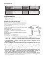
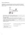
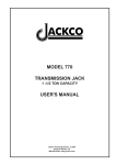
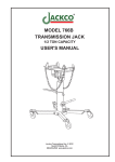
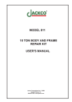
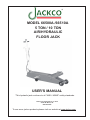
MODEL 66500A /66510A
5 TON / 10 TON
AIR/HYDRAULIC
FLOOR JACK
USER'S MANUAL
*This hydraulic jack conforms to all "ANSI / ASME" safety standards.
Jackco Transnational Inc. © 2012
South El Monte, CA
888-452-2526
To see more jackco products please visit our website at www.jackco.com
FOR YOUR SAFETY
• Read these safety instructions carefully and keep this manual in an easy to find place as
you may need to use it again.
• Non-compliance with these rules may result in injury or damage to the jack or the vehicle.
• Do not modify the jack in any way.
• Never exceed the rated capacity of the jack.
• This jack is a lifting device only and should never be used to move the vehicle.
• The jack should be supported on a solid and level ground. Never use the jack in a surface
where it may sink into the ground.
• Ensure that there are no persons inside the vehicle to be lifted. Switch off the engine and
apply the brake.
• Position the jack under the manufacturer’s recommended lifting point for the vehicle. Offcentered loads can slip and accidents may result.
• During raising and lowering of the load, precautions should be taken to avoid movement
of the vehicle. Traffic may cause the raised vehicle to rock during roadside use of the
jack.
• Never work under a raised vehicle without supporting it with mechanical/jack stands.
• Never position any part of your body near the movable parts of the jack.
• Ensure that there are no persons or obstructions underneath the vehicle prior to lowering.
• Do not adjust the overload bypass valve under any circumstance.
Use wheel chocks appropriately.
2
SPECIFICATION
Capacity:
Max Height :
Min Height :
5 Ton
560 mm/ 22 inch
150 mm / 5.9 inch
Lifting Height :
Gross Weight
Net Weight :
Capacity:
Max Height :
Min Height :
10 Ton
560 mm / 22 inch
160 mm / 6.2 inch
Lifting Height :
Gross Weight
Net Weight :
410 mm / 16.1 inch
106 kg/ 233 lbs
92 kg / 202 lbs
400 mm / 15.7 inch
156 kg / 343 lbs
139 kg / 306 lbs
SETUP
Assemble the handle
1. Loosen the bolt on the handle socket.
2. Insert the handle.
3. Tighten the bolt.
Bleed Air From the Service Jack
Air can accumulate within a hydraulic system during
shipment or after prolonged use. This entrapped air
causes the jack to respond slowly or feel “spongy”
To remover the air:
1. Open the release valve by turning the release knob
counterclockwise.
2. Pump the jack handle six full strokes.
3. Close the release valve by turning release know
clockwise.
4. If the jack does no immediately respond, respond,
repeat Steps1-3.
OPERATING INSTRUCTION
(Refer to the illustration above)
Control Rod in Position A: Allows you to pump the jack using the handle.
Control Rod in Position B: Locks the handle in place in three different positions.
1.C onnect the shop air supply to the jack (shop air should be clean, dry and
regulated at 85-120 psi)
2.Turn release knob completely counterclockwise, and place the control rod in
position A.
3.Position the jack under the vehicle using the manufacture’s recommended lifting
points on the chassis. The jack must be free to roll without any obstructions while
lifting or lowering the vehicle. The wheels of the vehicle must be in the straightahead position, with the emergency brake released.
4.Turn the release knob on the jack completely clockwise. Operate the air valve,
pump the jack handle, or pump the food pedal until the saddle touches the
vehicle. Check the placement of the saddle lugs. Finish lifting the vehicle.
5.Place approved safety stands under the vehicle at points that will provide support.
Before working on the vehicle, SLOWLY lower the vehicle onto the safety stands
3
by turning the release knob counterclockwise.
Preventive Maintenance
Important: Dirt is the greatest single cause of failure in hydraulic units. Keep the
service jack clean and well lubricated to prevent foreign matter from entering the
system. If the jack has been exposed to rain, snow, sand or grit, it must be cleaned
before it is used.
• Store the jack in a well-protected area where it will not be exposed to corrosive
vapors, abrasive dust, or any other harmful elements.
• Refer to the illustration, and regularly (at least once per month) lubricate the
moving parts shown.
• Add grease to upper arm grease nipple (shown) every three months.
• If necessary, add approved anti-wear hydraulic jack oil. Important: the use of
alcohol, hydraulic brake fluid, detergent motor oil, or transmission oil could
damage the seals and result in jack failure.
• Inspect the jack before each use. Take corrective action if any of the following
problems are found:
a. Cracked or damaged frame
b. excessive wear , bending, or other damage
c. Leaking hydraulic fluid d. Scored, damaged piston rod
e. Malfunctioning swivel heads or
adjusting screws
f. Loose hardware
g. Modified or altered equipment
4
TROUBLESHOOTING
Caution: To prevent personal injury, all inspection, maintenance, and repair
procedures must be performed when the jack is free of load.
Trouble
Jack does not lift
Cause
1. Release valve is open
2. Low/ no oil in reservoir
3. Air-locked system
4. Load is above capacity of jack.
5. Delivery vale and/or bypass
valve not working correctly.
6. Packing worn out of defective.
7. Leak in air line
8. Inadequate air pressure.
Solution
1. Close release valve.
2. Fill with oil and bleed system.
3. Bleed system.
4. Use correct equipment.
5. Clean to remove dirt or foreign
matter. Replace oil.
6. Install seal kit.
7. Locate leak; tighten
connections
8 Set air pressure to 85-120 psi
Jack lifts only partially
1.too much or not enough oil
1.Check oil level
Jack advances slowly
1. Pump not working correctly.
2. Leaking seals.
1. Install seal kit, or replace power
unit.
2. Install seal kit.
Jack lifts load, but
doesn’t hold
1. Cylinder packing is leaking.
2.Valve not working correctly
(suction, delivery, release, or
bypass)
3. Air-locked system.
1. Install seal kit.
2. Inspect Calves. Clean and
repair seat surfaces.
3. Bleed system.
Jack leaks oil
1. worn or damaged seals
1. install seal kit
Jack Will not retrack
1. Release valve is closed
1.open or clean release valve.
Air motor won’t run or
runs erratically
1. Leak in air line.
2. Inadequate air pressure
3. Air piston is sticking
1. locate leak, tighten
connections, or replace hose.
2. Set air pressure to 85-120 psi.
3. Lube air motor by adding a
small amount of oil to jack’s air
inlet
5
PARTS LIST
Description
Frame
Front wheel
Washer
Snap ring
Grease fitting
Rod link
Bolt
Saddle
Lock washer
Nut
Spring
Bolt
Bolt
Snap ring
Shaft
Rear wheel
Nut
Snap ring
Shaft
Washer
Pin
Connection bar
Spring
Snap ring
Shaft
Cover board
Snap ring
Washer
O-ring
Piston rod
Piston ring
Sealing washer
O-ring
O-ring retainer
Snap ring
Oil cylinder ass’y
Oil filler plug
Part No.
1-1
1-2
1-3
1-4
1-5
1-6
1-7
1-8
1-9
1-10
1-11
1-12
1-13
1-14
1-15
1-16
1-17
1-18
1-19
1-20
1-21
1-22
1-23
1-24
1-25
1-26
2-1
2-2
2-3
2-4
2-5
2-6
2-7
2-8
2-9
2-10
2-11
1
2
2
4
3
2
2
1
2
2
1
2
1
2
1
2
4
2
1
1
1
1
1
2
1
1
1
2
1
1
1
1
1
1
1
1
1
Q’ty
2-12
2-13
2-14
2-15
2-16
2-17
2-18
2-19
2-20
2-21
2-22
2-23
2-24
2-25
2-26
2-27
2-28
2-29
2-30
2-31
2-32
2-33
3-1
3-2
3-3
3-4
3-5
3-6
3-7
3-8
3-9
3-10
3-11
3-12
3-13
3-14
3-15
Part No.
Steel ball
Ball seat
Spring
Screw
Sealing washer
Bolt
Steel ball
Copper washer
Bolt
Steel ball
O-ring
O-ring
Release valve rod
Pin
Copper washer
Oil valve body
Nylon gasket
Cylinder pump
O-ring
Washer
Pin
Cylinder Pump Plunger
Handle socket
Pedal
Nut
Washer
Bolt
Handle
Sleeve
Knob
Pin
Control nod
Spring
Washer
Screw
Rod Joint
Spring
Description
1
1
1
1
1
1
1
1
1
1
1
1
1
1
2
1
1
1
2
2
1
1
1
1
1
1
1
1
2
1
1
1
1
3
3
1
1
3-16
3-17
3-18
3-19
4-1
4-2
4-3
4-4
4-5
4-6
4-7
4-8
4-9
4-10
4-11
4-12
4-13
4-14
4-15
4-16
4-17
4-18
4-19
4-20
4-21
4-22
4-23
4-24
4-25
4-26
4-27
4-28
4-29
4-30
4-31
4-32
Q’ty Part No.
Universal Joint ass’y
Convey Rod
Washer
Pin
Copper Washer
Oil Valve Body
Nylon gasket
Pump cylinder
Oil seal
Washer
Copper Washer
Nut
Bolt
Front cover
Steel ball
Air pump housing
Nut
Spring
Washer
Cylinder pump plunger
Piston body A
O-ring
Air release rod
O-ring
Piston body B
Bolt
Air seal
O-ring
O-ring
Rear cover
Snap ring
Snap ring
O-ring
Air valve
O-ring
Nylon gasket
Description
1
1
1
2
2
1
1
1
1
1
1
1
8
1
4
1
1
1
1
1
1
1
1
2
1
3
1
2
1
1
1
1
2
1
3
2
Q’ty
LIMITED ONE YEAR WARRANTY
Jackco Transnational Inc. warrants all Jackco equipment and tools to the original purchaser against any manufacturing defect in material or
workmanship for a period of one (1) year from the original date of purchase. If the defective equipment or tool is determined to be covered under
this warranty, it shall be repaired or replaced at manufacturer's discretion without charge, provided that the equipment or tool must be returned
with proof of purchase to the dealer and freight prepaid, if returned to the manufacturer. This warranty shall not apply to damage due to accident,
negligent use, and lack of maintenance, abuse or applications other than the specific function the equipment or tool is designed for.
No other warranties, expressed or implied, including those of merchantability or fitness for particular purpose shall be applicable to Jackco
except as specifically stated herein. In no event shall Jackco be liable to any party for any special, direct, indirect, consequential, punitive
damage of any nature caused by the sale or use of the equipment or tool.
Note: This warranty gives the original purchaser specific legal rights which may very from state to state.
Jackco Transnational Inc. © 2012
South El Monte, CA
888-452-2526 www.jackco.com