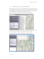
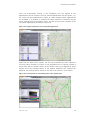
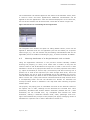
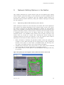
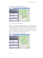
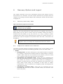
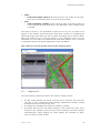
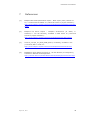
1
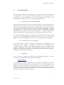
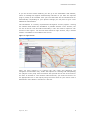
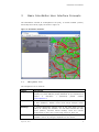
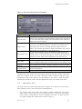
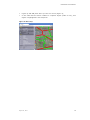
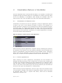
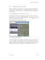
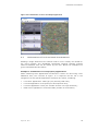
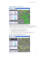
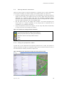
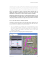
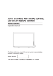
InterNetter User Manual Version 1.0 Delft, the Netherlands, August 2012 InterNetter User Manual Fred van der Wouden, Michiel Benjamins (DEMIS BV) Version 1.0 Delft, August 2012 InterNetter User Manual Contents 1 INTRODUCTION 4 1.1 Positioning of the InterNetter 4 1.2 Overview of the document 4 1.3 Support 4 2 GETTING STARTED 5 2.1 What is the InterNetter? 5 2.2 Starting up InterNetter 5 3 BASIC NETTER USER INTERFACE CONCEPTS 7 3.1 Navigation Tree 7 3.2 Vertical Toolbar 8 3.3 Working with Settings 9 3.4 Map Client Area 4 VISUALIZATION OPTIONS IN INTERNETTER 4.1 Visualization of Network Links 13 4.2 Visualization of Network Nodes 17 4.3 Combinations of Link and Node Visualizations 18 4.4 Showing Attributes of a Single Network Link or Node 20 4.5 Navigating the map with the Netter 23 5 NETWORK EDITING OPTIONS IN THE NETTER 5.1 Specifying Which Edit Action(s) Are Active 25 5.2 Editing Network Attributes 26 5.3 Editing the Network Topology 29 6 RECOVERY OPTIONS AND LOGOUT 6.1 Recovery with Undo / Redo 34 6.2 Support for network error detection 34 6.3 Logging out 35 7 REFERENCES August 14, 2012 10 13 25 34 36 3 InterNetter User Manual 1 Introduction This document contains the User Manual for the Inter Netter network editing tool as developed by Demis. The User Manual contains a full description of the functionality of the InterNetter. For a short summarized overview of the InterNetter functionality we refer to the Quick Reference Guide. 1.1 Positioning of the InterNetter The online GIS network viewer and editor InterNetter has been developed by Demis from the bicycle editor that was developed for the Dutch bicycle union. The online network application has been further developed for specific EC project needs and has been used for the EC projects REORIENT, WORLDNET, ETISPlus and RETRACK. The data collection process of the EC Framework 6 project RETRACK ([1], [2] and [3]) and the EC Framework 7 project ETISPlus have greatly contributed to the accuracy and filling of network data within the tool. The online InterNetter application provides link and node network data that was provided by the WORLDNET and ETISPlus projects (based on 2005 network data), extended with RETRACK specific for the rail network and terminal nodes. 1.2 Overview of the document In this User Manual, Chapter 2 provides an introduction to InterNetter and the terminology used. Chapter 3 describes the basics of the InterNetter user interface. Chapter 4 explains the visualizations options in the InterNetter and chapter 5 deals with the network editing options. Chapter 6 provides some features for support and network error handling within InterNetter. Chapter 7 provides an overview of the references. 1.3 Support If you require any support concerning the InterNetter application, on either technical or organizational issues, please contact Demis: [email protected] The InterNetter provides a wide variety of functionality and actions that can be applied for editing the network and its attributes. This User Manual describes all single and some combined / complex actions that can be applied in the InterNetter, but when applying more complex actions on the network, it might be useful to contact Demis to get some directions for which method works best for the specific changes you want to perform. August 14, 2012 4 InterNetter User Manual 2 Getting Started In this chapter the general principles of the InterNetter tool are described and the structure of the document is laid out. 2.1 What is the InterNetter? The InterNetter is a web based software tool that allows for viewing and editing of network related data on the internet. It is an on-line GIS that can be used by a community of users for network editing. It could be described as a network Wiki. Within multiple EC projects the InterNetter was used to gather, update, validate and complete network related data. The base network data is based on 2005 ETISPlus network data, which is extended with specific attributes for the rail network and terminal nodes. For understanding this user guide, it is imperative that the terminology such as described in the frame below is well understood: Frequently used terminology Network objects: the collection of objects of the type network links, nodes and (link) points. Network link: a segment in the (road or other) network, that connects two nodes. The trajectory of the link is defined by the network points that form the network link. The network link can be of the type sea, inlan d waterway (IWW), road or rail and has a great number of attributes. Network node: a point where two or more network links meet. The network node is related to the type of network links it connects or can be a terminal or port. Network (link) point: a point on a network link that determines it’s trajectory but has no additional attributes. Attribute: a characteristic of a network link or node also referred to as property or parameter. Attributes are dependent of the type of the object; different network links have different attributes (see annexes A and B). Trajectory: the exact path a network link follows, which is determined by the position of the network link points. 2.2 Starting up InterNetter To run the InterNetter tool you need to have a PC that has: A web browser installed; Macromedia Flash player 9 or better installed (Flash 10 is recommended); A fast internet connection (ADSL or better). August 14, 2012 5 InterNetter User Manual If you do not have Flash installed, you can go to the InterNetter web address, where a message will appear automatically that asks if you want the required plug-in (Flash) to be installed. Click yes here and Flash will be installed and run automatically. Depending on your specific settings you may have to give a few additional confirmations. The InterNetter is currently implemented throughout various projects. Viewing the network data within the InterNetter is possible without a user account, but for use of the full view and edit functionality a user will need to request a user account. From Figure 1 can be seen that without a login account, only a limited toolbar is available in the middle of the screen. Figure 1: Login screen Once you have logged in by entering the user name and password, the navigation tree becomes fully visible with options for showing and manipulating the (objects in the) map. Also the toolbar with provide the full set of functions to be used. To be able to view network nodes and links, you must first zoom in to the appropriate level in the map by using the scroll wheel on your mouse. This is described in more detail in sections 3.3 and 3.4. August 14, 2012 6 InterNetter User Manual 3 Basic InterNetter User Interface Concepts The InterNetter consists of a Navigation Tree (left), a vertical Toolbar (centre) and a Map client area (right) as shown in Figure 2. Figure 2: InterNetter elements 3.1 Navigation Tree The navigation tree is used for: Option Description Log-in To log in or out as a user. It requires you to enter a user name (usually an e-mail address) and a password. If you would like to acquire a username + password, please contact [email protected] Presentation Allows for show / hide the Legend and additional features such as hide disabled / hidden colours and merge multiple colour legends Settings To change application settings such as the scale when you are editing or viewing the network. You can also activate the map cursor position, activate mouse tooltips, store the current configuration or store the current map extent for later use Actions To define a shortcut quick reference showing the actions are available / active by using the keyboard or the mouse August 14, 2012 7 InterNetter User Manual Option Description Network To set visualization options for the network nodes and links. Here for either links or nodes you can set the colour appearance, the size appearance, the text appearance, the visibility options and the shape appearance of the nodes Map To select which map (layers) to show in the map client area. In InterNetter currently the Google Map background is used. However it is possible to visualize various NUTS level regions as separate map layers Error Shows categories of (possible) errors in the network such as overview floating nodes and overlapping (non) connected nodes Lists Shows lists containing some special features such as remarks A more detailed description of the navigation tree and its practical use can be found in chapter 4 for the visualizations options in InterNetter and chapter 5 which describes the network editing options of InterNetter. 3.2 Vertical Toolbar The vertical toolbar is used to access functions directly. This is provided a s an alternative to the Mouse menu in the navigation tree. In the mouse-over of the buttons the short-cut keys are shown also. The actions supported in InterNetter are shown in Error! Not a valid bookmark self-reference.. August 14, 2012 8 InterNetter User Manual Figure 3: InterNetter toolbar options Zoom to the previous map view (if available) Zoom to the next map view (if available) Zoom in Zoom out Move the map Show full map Undo last action (if available) Redo last action (if available) Add link point (for the trajectory) Add node Add link Move a node or link point Show information on the selected node or link Remove a node, point or link Remove a node connecting two links and join the remaining links Link properties table (for editing the attributes) Node properties table (for editing the attributes) Set same value to one object after another Copy Paste 3.3 Working with Settings After logging in, the navigation tree will show a number of ex pandable nodes that contain a great number of options. The scale settings contained within the settings node are specifically important for visualization of network data in the map client area. These are represented by the following scale bars (The vertical toolbar is used to access functions directly. This is provided a s an alternative to the Mouse menu in the navigation tree. In the mouse-over of the buttons the short-cut keys are shown also. The actions supported in InterNetter are shown in Error! Not a valid bookmark self-reference.. Figure 3): August 14, 2012 9 InterNetter User Manual Figure 4: The scale setting menu in InterNetter Option Description Showing the current scale with a scale bar to change the Current scale setting; this indicator will automatically adjust when zooming in or out. An exact scale number can be entered in the textbox to adjust the scale accurately This allows changing the visibility of the network at a certain view level. The default setting is 1:400000. By zooming in to Visible from… the appropriate level in the map area by using the mouse wheel, the network will become visible. Should the user wish to adjust the level of visibility, it can be set here This allows changing the level at which the network can be Edit mode from… edited, which is set by default to 1:50000. When editing large network links or wanting to be able to view a larger area when editing, the edit mode can be adjusted to the desired level Map position Link width Display mouse tooltips Using NumLock the map position can be copied to the clipboard With the scale bar the width of links and the size of the nodes can be changed (applying a correction factor to the default size) This checkbox will enable / disable showing the mouse tooltips Stored To store the current Netter configuration (settings) or retrieve a configurations saved configuration Stored extents To save the current map extent or retrieve a saved map extent Adjusting the scale settings may be used to visualize and edit network nodes and links at a higher level. The user should be aware however that this may significantly reduce the speed of the visualization. The zoom in and out option alternatively could be used to set the appropriate level in the map client area. 3.4 Map Client Area The map client area (the right hand area of Figure 2) is where the real work is done. What you see in the map client area depends on: 1. The current scale of the map. The network remains invisible as long as the scale shown in the map client area (bottom left) is less than the “visible from” value in the Settings \ Scale \ navigation tree item. To solve this you can either change the “Visible from” value or zoom-in; August 14, 2012 10 InterNetter User Manual 2. The visibility options set in the navigation tree under network for links and for nodes. Here you can completely hide or show all links and all nodes, but you can also have specific links or node visible through the network appearance options in the navigation tree; 3. The map that is selected under the map menu. Currently only the Google maps background map is available. However the various NUTS levels are available as additional map layers that can be selected in InterNetter. What happens in the map area depends on the action(s) you have selected via mouse, keyboard or toolbar. The action that is selected from either the actions menu of the navigation tree or in the toolbar is connected: selecting an option in the toolbar will highlight the mouse action in the navigation tree and vice versa. Some actions will have an immediate effect, such as moving the map or to undo / redo specific actions. Other actions merely set the stage for performing actions, such as edit actions. Most actions are available as keyboard shortcut and as mouse action from the toolbar. When moving over the map and over specific objects on the map, the tooltip will show the current action that is available. This will also be shown in the action menu: the available options are shown in black text for the short cut keys and for the current action the explanatory text is shown in black. Figure 5, August 14, 2012 11 InterNetter User Manual Figure 6 and Figure 7 show an example of this mechanism: When for instance the move option is selected from the toolbar, three options become available: P (add point), M (move) and O (move map); Depending on the object you are hovering over, the relevant option is highlighted in the navigation actions menu: move map when you are not over a over a network node or link (Figure 5), move node when you are over a node ( August 14, 2012 12 InterNetter User Manual Figure 6) and add point when you are over a link (Figure 7); In the case that the action relates to a specific object (node or link), this object is highlighted in the map area. Figure 5: Move map August 14, 2012 13 InterNetter User Manual Figure 6: Move point Figure 7: Add point August 14, 2012 14 InterNetter User Manual 4 Visualization Options in InterNetter The first important step in working with the Netter is to be able to visualize and navigate through the network data. The visualization of network links and nodes can be set separately in InterNetter. Both settings are available under the network menu item in the navigation tree and will be described subsequently. 4.1 Visualization of Network Links Visualization of network links can be organized by using the appearance options of colour, size, text or link visibility as shown in Figure 8. The selection of a specific attribute is limited to a set of attributes for which the appearance option is deemed useful. The network attributes Annex shows a full list of link attributes and the availability for appearance options. The links in the map area are only shown when the link check box is selected. If no specific appearance is selected, all links are shown without distinction. Figure 8: Selection of network link or node appearance When selecting a specific appearance, a legend is shown containing the values of the property of the network link. Any property (attribute) can be selected and a legend is automatically constructed based on the available values , specifically those values that are available in the current zoom area. This can vary from a simple yes / no value to a list of predefined values such as road numbers. 4.1.1 Col ou r appearan ce When selecting the colour appearance, automatically the last selected link attribute that was used by the user is shown here. In Figure 9 the network type is shown as an example of applying the colour appearance on an attribute. When links are drawn in black, the selected attribute of the link has not been given a value. In the case of the network type, this may be caused by the fact that the link has no link type value assigned (i.e. missing value). When selecting a specific appearance, also the ‘apply value’ box becomes visible if the attribute is editable. This allows for assigning a specific value to the links by selecting them. This is a specific edit action, which will be described elaborately in section 5.2.2. August 14, 2012 15 InterNetter User Manual Figure 9: Network type displayed by colour 4.1.2 Siz e appearan ce The size appearance can be assigned similar to the colour appearance, where a quantifiable property is displayed by the size of the link. This is quite useful for properties such as capacity or other link property that signifies a value within a certain range. In Figure 10 the number of lanes is selected as property for the size appearance. Figure 10: Number of lanes displayed by size 4.1.3 Text appearan ce The text appearance can be assigned similar to the colour or size appearance, where the value of the property is shown as text on the link itself. Since this is a August 14, 2012 16 InterNetter User Manual free form field, there are hardly any limitations to the properties that can be shown this way. The text itself is less distinctive in presentation than the colour or size appearance, but may well be used in addition to the before mentioned appearances. Take note that the text will only be visible when in edit mode; the user needs to be zoomed in enough to make the text show up. In Figure 11 an example of the free flow speed is shown. Figure 11: Free flow speed displayed as text 4.1.4 Vi sibility of links The visible appearance is a means of restricting the visibility of links when not conforming to a specific attribute value. For a specific attribute, the full list of values is shown with a check box that determines the visibility of links with that value. Also the ‘hide all’ option is available to hide all links that have a value for this attribute. This may be useful when making a selection of the rail network type, where the other network types should be hidden, as shown in Figure 12. Figure 12: Rail network visibly displayed August 14, 2012 17 InterNetter User Manual For corridor purposes specifically, a specific corridor can be selected for visualization. This allows for isolating visualization to the specific corridor study, as illustrated in Figure 13 the RETRACK main and alternative corridor. Figure 13: Visibility based on RETRACK Corridor Selection 4.1.5 Multiple appearan ce sel ections The InterNetter allows for selection of multiple visibility appearances. In Figure 14 below the [+] icon next to the visibility (and also available for color) selection indicates that more selections are possible. Figure 14: Multiple Visibility selections Clicking the [+] will result in extending the visibility selections by another checklist, thereby allowing making multiple visibility limitations. E.g.: the visibility of the RETRACK corridor (Main and Alternative) may be set and in addition only the railway lines with 2 or more tracks may be selected. Section 4.4 will describe some options for multiple color appearances and the use of the legend. August 14, 2012 18 InterNetter User Manual 4.2 Visualization of Network Nodes Similar to visualizing the network links, the network nodes can be organized by way of a specific appearance selection. In addition to the appearances that are available for the network links, also the shape appearance is available for network nodes. 4.2.1 Appearan ces also occu r ring in links The same basic principles are applicable to the nodes as to the network links. The colour, size, text and visibility appearance are similar to the link appearances. In Figure 15 an example is shown of the colour appearance for the number of connected roads to the node. Figure 15: Number of connected roads for nodes 4.2.2 Shape appearan ce The shape appearance is an appearance specifically applied to network nodes. In the current version of the InterNetter network the shape appearance does not have very significant added value, since only terminal and port nodes are defined. Figure 16 gives an example of a combination of colour and shape appearance: ports are shown as green squares, terminals as red circles. August 14, 2012 19 InterNetter User Manual Figure 16: Combination of colour and shape appearance 4.3 Combinations of Link and Node Visualizations Showing a single attribute of the network node or link is usually too limited for the user’s purpose. The InterNetter specifically supports showing multiple network attributes that can be chosen by the user. Below two examples are given to demonstrate this feature. Example 1: Combination of road property appearances When combining some appearances mentioned in section 4.2 and using a few additional ones, the overview of Figure 17 is acquired. On the left in the navigation tree the specific appearance selections are shown, combining: Link colour appearance: road type (only showing road links); Link size appearance: free speed (free flow speed of lane); Link text appearance: lanes (the number of lanes in a single direction) ; Node colour appearance: connected roads (number of connections). August 14, 2012 20 InterNetter User Manual Figure 17: Combination of road properties Example 2: Inland Water Way related link appearances InterNetter contains Inland Water Ways (IWW) related data, although this may not be as detailed as the road data. In Figure 18 a few IWW related features are shown, that combine the following settings in the navigation menu: Link colour appearance: Inland Water Ways type; Link size appearance: TCTonnes (transported Tonnes); Text appearance: Length (length of the link); Link visible appearance: IWW type, so only the IWW network is shown ; Node colour appearance: network type (IWW shown in yellow). Figure 18: Combination of IWW related properties August 14, 2012 21 InterNetter User Manual 4.4 Customizing colour or shape appearances As could be seen in section 4.1.5 the InterNetter allows for choosing multiple visibility appearances. Apart from that, also the colour appearance can be chosen to be applied to more than one attribute. In Figure 19 two colour appearances have applied for the attributes ‘Type’ and ‘Network Category’. Figure 19: Multiple colour appearances applied with a merged legend Alternatively when displaying multiple colours a separate display can be chosen so that colour values are shown as two separate lines as in Figure 20. Figure 20: Multiple colour appearances applied with a merged legend August 14, 2012 22 InterNetter User Manual From the presentation section in the navigation tree the legend of the appearances can be selected. Here all selected appearances will be shown, e.g. the colour and size appearance in Figure 21. When multiple colour appearances are available, it is possible to combine the colour schemes by selecting ‘merge colour-legends from the navigation menu; this will mix the colour schemes of the tow colour appearances as shown in Figure 19. Figure 21: Legend opened for colour and size appearance Apart from the basic colour options, the user can customize the colour legend to his liking. When clicking on a colour in the navigation tree or Legend, a pallet is shown from which a specific colour can be chosen. This can be applied to single colours and to the merged colours in the Legend. Whenever the schemes are adjusted, the settings will be stored for the user to be used in a next session. Figure 22: Colour pallet for customizing the colour appearance August 14, 2012 23 InterNetter User Manual The customization can also be applied to the names of the attribute values, whch is valid for colour and other appearances. Additional customization can be applied to the size appearance: when the attribute displayed is a set choice list, the size of the attribute can be chosen with a scale bar as shown in Figure 23. Figure 23: Size bar for customizing the size appearance The navigation tree contains an option for hiding hidden colours, which can be applied to attributes that are not applicable (and can be hidden) for a specific network type, e.g.: the rail network may be showing road attributes that are not applicable (these are hidden so showing as grey), so these can better be hidden. 4.5 Showing Attributes of a Single Network Link or Node Using the appearance selections in the previous sections basically enables showing one property (or more) of all visible links or nodes. It may also be useful to show or edit all attributes of a single link or node. A list of link or node attributes is shown as a popup window when the ‘list with properties and values (L)’ option is activated (or a move map / zoom action) and when hovering over a specific link or node in the map area (at a close enough zoom level). There will be two effects: the link or node is highlighted and a (non-editable) list of link or node attributes shows up. When a link or node specific action is selected such as add or remove link / node, this function is dominant and the map area will show a corresponding action and not the attribute list. Section 5.1 describes the concept of which action is available in the map area when selecting a specific toolbar option. The property list popup gives an immediate overview of the attribute values of the specific link or node, although not all attributes are included here. More specifically: attributes that contain another dimension (besides the link / node dimension) are not included here, e.g. FreeSpeed that contains the mode dimension, making a distinction between boat, coach, passenger and truck. Figure 24 illustrates the principle of the property list popup. Changing values of attributes for a specific link or node is described in section 5.2. August 14, 2012 24 InterNetter User Manual Figure 24: Showing all attributes of a specific object (link or node) 4.6 Navigating the map with the Netter In the actions menu, several mouse and keyboard options are available for navigating the map. The specific actions are also supported in the toolbar and can be activated by selecting the option either way. Although most of these actions are intuitive, they are described here for purpose of completeness. Figure 25: Navigation related toolbar options Zoom to the previous m ap view (if available) Zoom to the next m ap view (if available) Zoom in Zoom out Move the m ap Show full m ap Show or hide the m ap layer legend This set Show of navigation options are m the or hide the overview aponly options a user has available when he is not signed in asinaWorld registered Not used Netteruser. Options for getting detailed information and editing functionality only become available when logging in to the InterNetter. Not used in World Netter Undo last action (if available) Redo last action (if available) Add point (for a trajectory) Add August 14, 2012 node Add link Move a node or point 25 InterNetter User Manual Figure 25 shows the following actions as they occur in the vertical toolbar: Zoom to the previous map view (if available): the map views the user creates are stored in memory, allowing return to a previous zoom; Zoom to the next map view (if available): as above; Zoom in: this option (in the form of drawing a window to zoom in to) is also available in the scroll wheel of the mouse by scrolling up; Zoom out: this option (in the form of drawing a window to zoom out of) is also available in the scroll wheel of the mouse by scrolling down; Move the map: this is the default setting: grabbing the map and moving it in the desired direction will move the map and redraw the attributes; Show full map: in the case that the full world map needs to be shown, this option allows the full zoom. It can also be a remedy in the case the undesirable effect of a locked map occurs (where the user is unable to move the map). August 14, 2012 26 InterNetter User Manual 5 Network Editing Options in the Netter This chapter discusses the various actions that can be applied when editing network objects (links and nodes) or their attributes. First the available actions at any given moment are explained. Next the separate editing actions are described: editing network attributes, editing the network topo logy and editing the link trajectory. 5.1 Specifying Which Edit Action(s) Are Active When moving the mouse over the map area, the actions that can be applied at that moment will change depending on the network object (if any) over which the mouse is hovering, as was briefly addressed in section 3.4. The action(s) that is (are) available, are always the most logical ones given the selection of a specific functionality. When an edit function is selected, the most logical function is suggested when hovering over an object, which may not always be the selected function. The available mouse actions will be shown coloured in the mouse menu (P, M and O in Figure 26); selecting the action through the keyboard shortcut will show the shortcut in red. The specific active action’s description will be shown in black (‘add point’). For example: When ‘add point’ is selected, this generally creates a new (link) point when clicking on a link. When hovering over an existing point or node, instead the function ‘move point’ or ‘move node’ is available. When not hovering over any object, the default function ‘move map’ becomes available; Instead of the ‘add point’, also ‘move point’ or ‘move node’ may be selected from the toolbar. It has the same effect on available functions; The ‘remove’ action is more generic: it can be applied to any object that may be removed. Figure 26: Options (in left navigation menu) when the mouse is over a link August 14, 2012 27 Zoom to the next m ap view (if available) Zoom in Zoom out InterNetter User Manual Move the m ap Show full m ap 5.2 Show or hide the m ap layer legend Editing Network Attributes Show or hide the overview m ap Not usedways in World Netter There are three to edit the attributes of a network link or node, depending on the type change youNetter want to apply (see toolbar options in Figure 27): Not of used in World Using the properties table to edit one or more attributes of a specific network Undo last action (if available) object (link or node). This allows the user to open a table with (most of) the Redo last (if available) attributes of action a specific object and edit any attribute presented there; Add point a trajectory) attributes that(for contain multiple dimensions (such as FreeSpeed that contains also Add the ‘mode’ node dimension) are not available here; Set the same value to one object after another: this allows assigning the sameAdd value link for a specific attribute to any object that is selected; this is available for all (editable) attributes; Move a node or point Copy and paste all values of an object: use the copy and paste functionality Show on object the selected node or link to copy allinform valuesation of one to another. Rem ove a node or point or link Figure 27: Options for editing network attributes Rem ove a node or point or link and join rem aining network item s Link properties table (for editing the attributes) Node properties table (for editing the attributes) Set sam e value to one object after another Copy Paste 5.2.1 Using th e properti e s tabl e To edit one or more attributes of a specific network link or node, the option for editing attributes through the properties table can be selected (shortcut keys F for links and D for nodes) as shown in Figure 28. Figure 28: Editing link attributes through the link properties table August 14, 2012 28 InterNetter User Manual This allows the user to open a table with the attributes of a specific object and edit any attribute presented here. Take note that dimension dependent attributes are not available in the list; in order to change these, you must work with the ‘apply one after another’ option. The network link attributes table is shown in Figure 28; to the right of the current value the history of the last edit action is shown. The properties list shows a distinction between attributes that are editable and read-only. Attributes that are shown in grey in the list are not applicable for the selected link or node type and are therefore not editable. Although the properties list allows the user to edit almost all attributes, it is not the most practical way to modify values. This can either be done by assigning values for one attribute at a time to one (but usually more) objects or by copying and pasting all attribute values from one object to another. 5.2.2 Set same valu e to multiple obj ects The option to ‘Set the same value to one object after another’ (shown as an “S” in the navigation and properties list) allows assigning the same value for a specific attribute to any object that is selected as follows: The “S” is available in the navigation when a certain appearance is active and if the attribute is editable: selecting the “S” shown before a legend value will check the ‘apply value’ box with the indicated value set to be applied, as shown in Figure 29. The change in the attribute value is shown when hovering over the object; Figure 29: Preparations for assigning values to subsequent objects August 14, 2012 29 InterNetter User Manual Alternatively, select the attribute and value in the properties table from the previous section. Clicking the “S” next to the attribute value allows the use for other objects; the property table will automatically close; Select any node or link you wish to assign the value to for the chosen attribute. A tooltip will show the effect of the action when hovering over an object of the right type. It is possible to simultaneous edit a link and a node attribute if the ‘apply value’ is set for both a link and node attribute. 5.2.3 Copy and paste all valu es of an obj ect When all attribute values of a certain object are relevant for another object, it is useful to copy and paste the attribute values of this object by: Select the ‘Copy’ action (or keyboard key C), followed by the source object; the full list of object attributes will be shown in the navigation menu. In this list it is possible to uncheck a specific attribute to avoid copying it ; Select the ‘Paste’ action (or keyboard key V), followed by the target object; Before applying the paste action, an attribute overview will be shown when hovering over the target object, showing a list of old and new values if the paste action would be executed. When a value will be changed, the old and new values are shown in ‘bold’ character type which is shown in Figure 30. Figure 30: Attribute values list of old and new values before pasting August 14, 2012 30 InterNetter User Manual 5.3 Editing the Network Topology Apart from editing network object attributes, where the network topology remains the same, there are several actions where the positioning of nodes and links can be altered or objects can be added or removed. The specific actions designed for editing a link trajectory are described in the section 0. Here the following actions are illustrated (as shown in Error! Reference source not found.Figure 31 from the toolbar): Adding nodes or links; Removing nodes or links; Moving nodes (and thereby the links). Figure 31: Options for editing the network topology Add node Add link Move a node or link point (Show information on the selected node or link) Remove a node, point or link Remove a node connecting two links and join the remaining links 5.3.1 Adding n odes and lin ks Adding a node to the network can only be done on an existing network link. Either a new point can be created on the link or an existing point can be turned into a node. In both cases the ‘add node’ action (keyboard key K) is used by: Select the toolbar action ‘add node’ (or keyboard key K); Select a position on an existing link (which may be an existing point, but this is not necessary); The add node tool tip will appear and the related point (if any) will highlight; click the position to add the node (as is shown in Figure 32). To adjust attributes of the node, you can use the methods as described in section 5.2. August 14, 2012 31 InterNetter User Manual Figure 32: Adding a node to a network link Adding a link to the network can be done at any position on the map and it is not mandatory (although it is good practice) to connect this directly to the existing network. The following actions are needed to create the new link: Select the toolbar action ‘add link’ (or keyboard key T); Click on the map to select the starting point of the link. Every next click on the map will add link points, by which you can determine the trajectory of the link, as illustrated in Figure 33. The link is drawn in grey as long as it is not accepted or cancelled, which shows that the editing is in progress; When finished with drawing the link, you can either apply the link by pressing [Enter] or cancel by pressing [Esc] on the keyboard. When cancelling the link disappears, when applying the link is drawn in black; InterNetter will automatically turn the begin- and endpoint into a node and all intermediate points into (link) points. When the begin- or endpoint is positioned on an existing link, a node is created and the link will automatically be split in two separate links with identical attributes; After having added the link, it is possible to edit the attribute values as described in section 5.2. August 14, 2012 32 InterNetter User Manual Figure 33: Adding a link to the network 5.3.2 Removing n odes an d lin ks The ‘remove’ action can be applied to every object on the map: nodes, links and points. It is simply performed by selecting the ‘remove’ action from the toolbar (or the keyboard key X) and selecting the object subsequently (which will show the remove object tooltip) or by pressing the [Delete] button when moving over a network object. Since removing objects can have serious consequences, please take note of the following observations: Removing a link will remove the link, all its attributes and link points, but the nodes to which it is connection will not be removed; Removing a (link) point on a link will only remove the point, thereby only changing the trajectory of the link. An elaborate description of options for editing the link trajectory can be found in section 0; Removing a node will not only remove the selected node, but will also remove all links that are connected to the selected node. Since this may be highly undesirable, the ‘remove and join’ action is available, which will be described next. August 14, 2012 33 InterNetter User Manual The ‘remove and join’ action is a specific action to remove a network node, but to leave the connecting links intact. This can only be applied when: The node that connects exactly 2 links; The two links need to possess exactly the same attribute values. If one of these conditions is not met, the action will not be performed and a popup appears stating the reason why, as illustrated in Figure 34. To ensure that the two links have exactly the same attribute values, the copy and paste function may be useful to copy all attribute values of one link to the other. If the user may want to perform more complex calculations to determine the attribute values of the resulting link, it would be best to perform these first and assign the values to one of the links’ attributes. After this, the values can be copied to the other link and the remove and join action can be performed. Figure 34: Trying to apply a remove and join action 5.3.3 Movin g n odes As could be seen in the previous section in the case of deleting, actions on a node has direct consequences for the links it connects. This is also the case when moving a node: when moving a node, the dragging also shows the changes that will be applied to the (trajectory of the) links. This is illustrated in Figure 35, where a node is being moved and the black lines show the new positioning and the green lines show the former positioning of the links. August 14, 2012 34 InterNetter User Manual Figure 35: Moving a node and connected IWW links 5.3.4 Editing th e Link Trajectory When a link is not positioned well on the map, the user may want to edit the trajectory of the link using the link points. These points have no attributes and are easy to drag to alter the link position. All actions to the link points are comparable to those used for nodes (add, remove, move), but the consequences of, for example removing a link point, are less severe since it only result in changing the trajectory of the link. Figure 36 illustrates the action of moving a point: the (purple) point is dragged, where the grey line shows the new trajectory, the green link showing the current link trajectory. Figure 36: Moving a point and the connected link August 14, 2012 35 InterNetter User Manual Zoom to the previous m ap view (if available) 6 Recovery Options and Logout Zoom to the next m ap view (if available) Zoom in Zoomdescribes out This chapter some of the InterNetter features that support recovery and network error detection. The final section describes the principles that are Move the m ap related to the locking of network objects while editing the network and the effect Show of logging out.full m ap Show or hide the m ap layer legend 6.1 Recovery Undo /mRedo Show or hidewith the overview ap Not used in World Netter Figure 37: Recovery options in the toolbar Not used in World Netter Undo last action (if available) Redo last action (if available) Add point (for a trajectory) When the user has performed an action that was not intended, the Undo and Add node Redo actions can be used to recover from the situation. When the action is selected Add from linkthe toolbar (or by use of the Z or Y key), a tooltip is shown indicating which action will be performed when undoing or redoing an action. If a node point possible,Move the map willornavigate to the position where the undo / redo action will be applied. Show inform ation on the selected node or link Rem ove a node or point or link Take note that once the user logs out of the InterNetter from the login Rem ove a node or point or link and rem aining item s navigation menu, all changes arejoin accepted and network cannot be undone. Link properties table (for editing the attributes) Node properties table (for editing the attributes) Support for network error detection 6.2 Set sam e value to one object after another The Netter provides support for detecting possible errors to the network. In the Copy form of producing a few lists the following (possible) errors are made visible: Paste Nodes: Floating nodes: the basic assumption is that nodes should be connected to a network; otherwise the network cannot be used sensibly for network models. When nodes are not connected to the network, these are listed here; clicking a node in the list will link to its location; Overlapping non-connected nodes: nodes that are overlapping but that are not connected may be a result of double nodes being present in the network. Of course it is possible that nodes are overlapping, for instance a terminal and a port that are located at the same point, but these nodes would usually be connected to each other to enable transshipment. This list detects the overlapping nodes and displays the node pairs involved; Overlapping connected nodes: nodes that are overlapping but are connected may still be the result of double nodes; this overview lists these node pairs; August 14, 2012 36 InterNetter User Manual Links: Links with length equal to 0: these links are not visible on the map, but may be unnecessary links or have the wrong length; Lists: Links containing remarks: these links may have received a remark by a user because of some peculiarity in the attributes, which implies action is needed. The whole overview is not generated to point out errors, but to improve the quality of the network by providing the users with a means of evaluating the network through issues that may not be visible by looking at the network maps. Figure 38 shows the error overview options in the navigation menu. The list presented here can easily be extended with some data specific error overviews or dedicated lists for the specific application of the InterNetter. Figure 38: Error overview and list options in the navigation menu 6.3 Logging out The logout action in particular ends a user session, which involves: All (last used) settings are saved, so these will be used the next time the user logs in. This includes the scale settings, appearances settings, legend settings and the zoom of the map area; All changes are accepted and cannot be undone or redone; All objects that the user has made changes to were locked for other users during his user session (to prevent more users working on the same objects simultaneously). When signing out, these objects are unlocked, so other users can work on them as well. August 14, 2012 37 InterNetter User Manual 7 [1] References ETISplus D2 Draft Specification Report - Main report (Chen, Newton et al): v3 R20100326 available on (restricted access to project members): http://www.etisplus.eu/documents/restricted/Restricted%20Documents/F orms/ [2] ETISplus D2 Annex Report – ETISplus Architecture (R. Smith, P. Grashoff, F. van der Wouden), available in WP5 folder on (restricted access to project members): http://www.etisplus.eu/documents/restricted/Restricted Documents [3] General_concept_for_ETIS_BASE_data (P. Grashoff), available in the (restricted) WP 11 folder on: http://www.etisplus.eu/documents/restricted/Restricted Docum ents [4] ETISNetter Quick Reference Guide (F. van der Wouden, M. Benjamins), available in Retrack Knowledge Base: http://retrack.demis.nl/RotterdamConstanza/SitePages/Documents.aspx August 14, 2012 38