1
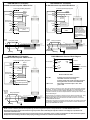
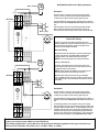
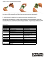
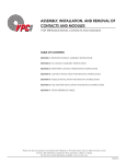
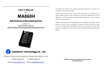
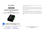
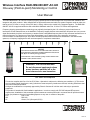
Wireless Interface RAD-ISM-900-SET-AC-UD
One-way (Point-to-point) Monitoring or Control
User Manual
The RAD-ISM-900-SET-AC-UD is a Frequency Hopping Spread Spectrum radio designed for the professional installation and
integration with other products. When installed with an approved antenna and cable, the system integrator needs to make sure
that the unit's FCC label, or a copy of that FCC label, is clearly visible on the outside of the integrated product. The RAD-ISM900-SET-AC-UD is approved within the 902 to 928 MHz ISM Band under Part 15 of the FCC Rules and Regulations.
Frequency hopping spread spectrum technology was originally developed by the U.S. military to prevent interference or
interception of radio transmissions on the battlefield. Frequency hopping devices concentrate their full power into a very narrow
signal and randomly hop from one frequency to another within a designated frequency band. If they encounter interference on a
particular frequency, the devices error check the affected data, hop to another point on the spectrum, and resume
communications on subsequent hops. Since there are always spaces without interference somewhere in the allotted radio
spectrum, a frequency hopping device will use those spaces to complete a transmission.
)
)
)
)
)
)
)
)
)
NOTICE
These devices must be wired in accordance with Class I, Division 2
wiring methods as described in the National Electrical Code, Article
501-4(b) or the authority having jurisdiction.
Transmitter unit is to be used with a purely resistive antenna when
installed in Class I, Division 2 areas.
WARNING: EXPLOSION HAZARD
Do not disconnect equipment unless
power has been switched off or the
area is known to be non-hazardous
FCC Rules and Compliance
This device complies with Part 15 of the FCC Rules. Operation is subject to the following two conditions: (1) This device
may not cause harmful interference, and (2) this device must accept any interference received, including interference that
may cause undesired operation.
Changes or modifications not expressly approved by Phoenix Contact will void the user's authority to operate the
equipment.
This product is intended for fixed installation applications. In order to comply with FCC/ISC adopted RF exposure
requirements, installation of this transmitter system's antennas must be performed in a manner that will provide at least a
6 foot (2m) clearance from the front radiating aperture to any user or member of the public.
FCC
Part 15.247
ISC
RSS 210
UL
Class I, Div 2 (Groups A,B,C,D)
Rev 1.8
RAD-ISM-900-AC Transmitter
4-20mA Current Loop with 2-Wire Device
RAD-ISM-900-AC Transmitter
4-20mA Current Loop with 3-Wire Device
Customer Supplied Wiring & Equipment
Customer Supplied Wiring & Equipment
Ground
Green
Neutral
White
(Power Neutral)
100 to 240VAC
Black
Green
Ground
White
(Power Neutral)
Neutral
100 to 240VAC
Black
0.5A Fast
Blow Fuse
Gray (Discrete
Inputs Common)
Gray (Discrete
Inputs Common)
Discrete Input 1
Orange
+
-
Red
Blue
Brown
Red
Blue
Brown
4-20mA Current Loop
(2-wire)
Current
Source
Brown
Used in 3 and 4 Wire Current Loops
Red
Blue
Discrete Input Common
-
Green
White
Black
Grey
Ground
Neutral
100 to 240VAC
+
Ground
Neutral
Discrete Output 1
10
11
Discrete Output 2
12
+
-
RF LED
4-20mA Current Loop
(4-Wire) Externally Powered Power
LED's 1 & 2
Brown
N/C
Used in 3 and 4 Wire Current Loops
Red
Blue
Discrete Input Common
Discrete Input 1
Discrete Input 2
Floating
Yellow
NO
COM
NC
NO
COM
NC
NO
COM
NC
1
2
RF Link
3
4
4-20mA Output
5
Ground (power and 4-20mA)
6
9 to 30VDC Power
- Flashes once every two seconds when
transmitter is OFF or out of range
- Flashes rapidly when signal strength is marginal
- Solid green when a secure link is established
- Show status of discrete inputs 1 & 2. Solid
green = ON
RF Link: Internal dry contact Form C relay. May be wired as Normally Open (NO) or Normally
Closed (NC). This relay is activated when a good Radio (RF) Link is established between the
Receiver and its matched Transmitter. DEFAULT STATE: When Link is lost between the
Transmitter and Receiver, this discrete output defaults to the normal position as shown in the
Receiver Block Diagram.
Analog Input (4-20mA)
+
Orange
Receiver Indicator LED's
Discrete Input 2
Yellow
8
9
Discrete Input 1
Orange
Neutral
Floating
7
0.5A Fast
Blow Fuse
Gray (Discrete
Inputs Common)
Grey
Ground
100 to 240VAC
RAD-ISM-900-AC Receiver Block Diagram
100 to 240VAC
Black
Green
White
Black
Discrete Input 2
Customer Supplied Wiring & Equipment
-
Blue
Discrete Input Common
Signal
Common
White
(Power Neutral)
Used in 3 and 4 Wire Current Loops
Red
RAD-ISM-900-AC Transmitter
4-20mA Current Loop with 4-Wire Device
Externally
Powered
Current
Source
Brown
Discrete Input 1
Floating
Red
Blue
Brown
Analog Input (4-20mA)
Yellow
Discrete Input 2
NOTE: DC Power Supply
Output on Red Wire is
rated at 25mA max.
If end device requires
more than 25mA then an
additional Power Supply
will be required to meet
the manufacturers
requirements for the end
device.
4-20mA Device
(3-Wire)
Orange
Discrete Input 1
Green
Discrete Input 2
Yellow
Analog Input (4-20mA)
+
Discrete Input 1
Orange
Discrete Input 2
Yellow
Current
Source
0.5A Fast
Blow Fuse
Green
White
Black
Grey
Orange
Yellow
Ground
Neutral
100 to 240VAC
Discrete Outputs 1 & 2: Internal dry contact Form C relays. May be wired as NO or NC. These
relays are activated when voltage is applied to Discrete Inputs 1 & 2 at the Transmitter.
DEFAULT STATE: When Link is lost between the Transmitter and Receiver, these discrete
outputs MAINTAIN LAST STATE.
Analog Output: The 4-20mA Current Output replicates the status of the 4-20mA Current Input at
the Transmitter. DEFAULT STATE: When Link is lost between Transmitter and Receiver, the
analog output MAINTAINS LAST STATE.
NOTE: Incorrect antenna placement and positioning can have a significant impact on the performance of the RAD-ISM-900-SET-AC-UD.
Keep the Omni antenna vertical and mounted as high as possible. Extra cable may be required to achieve Line-of-Sight (L.O.S.) between the
Transmitter and the Receiver.
For applications that require the antenna to be mounted away from the Transmitter, please contact your Distributor for cable and antenna options.
Always follow the mounting instructions and proper grounding procedures as outlined in the antenna manuals.
RAD-ISM-900-AC Receiver Wiring Examples
Meter (4-20mA)
+
Example A
- - +
Receiver
+
6
5
3
4
2
RF Link Contact is wired to a warning light using the (NC)
Contact. As soon as the RF Link has been established, this
contact will go to Open and the warning light will go out.
DC
OK
- - + +
1
POWER
+24V
GND 4-20mA
RF LINK
NO
NC
COM
- - OUT
+
DC
OK
+
+
+
24V
1A
The 4-20mA Analog output has been wired directly to a meter or
RTU/PLC device and will MAINTAIN LAST STATE if the RF Link is
lost.
Discrete Output 1 has been wired through the (NO) Contact.
When voltage is applied to the Discrete Input 1 side of the
Transmitter, this contact will go closed, and the Pump will start.
-
MINI-POWER
Warning Light
RF
2
+
22.5 - 28.5
V DC
DC
OK
-
If either one or both of the Discrete Outputs and or the
Analog (4-20mA) are required to default OFF upon loss of the
RF Link with the Transmitter, the RF Link Output can be
used to provide a Default OFF State.
1
Pump
DISCRETE
1
NO
COM
DISCRETE 2
NO
NC
COM
NC
IN AC 100-240 V
L(+)
7
8
9
10
11
12
NC
NC
L
Discrete Wiring
N(-)
By wiring the Discrete Output(s) in series through the (NO)
contact of the RF Link, the LAST STATE of the Discrete
Output(s) will be over-ridden and forced to go Open.
NOTE: Current rating of RF Link Contact is 0.5A max.
N
Meter (4-20mA)
Analog (4-20mA) Wiring
+
+
Likewise, if the Analog signal is required to drop to zero
(0 Current) when RF Link is lost, it can be wired in series to
the RF Link Output in this fashion.
NOTE: Either the Discrete Outputs or the Analog can be
wired through the RF Link contacts but not both!
- - +
Receiver
6
3
+24V
NC
5
4
2
1
POWER
GND 4-20mA
RF LINK
NO
COM
DC
OK
Maximum OFF voltage for the discrete input is 60VAC.
Use of a 2Watt 10k ohm resistor at 110VAC in parallel across
the input will help to ensure minimum and maximum ON and
OFF states.
- - + +
- - OUT
DC
OK
+
+
+
24V
1A
+
-
MINI-POWER
Warning Light
RF
2
Example B
+
-
22.5 - 28.5
V DC
DC
OK
1
Pump
NC
NC
DISCRETE 1
NO
COM
DISCRETE 2
NO
COM
IN AC 100-240 V
L(+)
7
8
9
10
11
12
Default OFF Wiring
L
NC
NC
N(-)
N
RF Link Contact is wired to a warning light using the (NC)
Contact. As soon as the RF Link has been established, this
contact will go to Open and the warning light will go out.
The 4-20mA Analog output has been wired directly to a meter or
RTU/PLC device and will MAINTAIN LAST STATE if the RF Link is
lost.
An interesting feature in this example is wiring of the pump.
Discrete Output 1 has been wired through the (NO) Contact, and
through the RF Link (NO) Contact. This immediately shuts off of
the pump if the RF Link is lost. By wiring through the RF Link
Contact in this way, the RF Link Contact will go Open when the
RF Link is lost, and the pump will shut down. This overrides the
default for Discrete Output 1, which MAINTAINS LAST STATE.
NOTE: The RAD-ISM-900-AC Receiver Analog Output is a 3-Wire device and should be wired to the RTU / PLC
just as you would a normal 3-Wire Current Loop Device.
This wiring configuration is for the Receiver only and must be followed regardless of the type of Current Loop
device on the Transmitter side of the loop (i.e. 2-Wire, 3-Wire, or 4-Wire).
Adding an Extra or Spare Receiver to your System
1) Remove the HopKey from the existing receiver by popping the divots on either side of the enclosure and removing the circuit board
(refer to the photographs). Remove the Hopkey and re-insert the circuit board into its enclosure. When re-inserting, line up the terminal labels
on the side of the enclosure with the terminal labels on the top of the circuit board to prevent it being installed backwards.
2)
Remove the spare receiver from its enclosure.
3)
Insert the HopKey from the original receiver into the spare receiver. Re-insert the circuit board into the enclosure.
Once power is applied to the spare receiver, it will memorize the identification, hop frequencies and hop sequence of the transmitter. This
takes a few seconds upon power up. If power is removed, it will retain this information, even if the HopKey is removed. Now your spare
receiver, along with the original receiver, will both respond to signals from the transmitter. Ensure you are using an omni directional antenna
at the transmitter if the receivers are off in different directions, since yagi directional antennas only send radio signals in one direction.
Specifications
Frequency
Technology
Power Source
Power Consumption
DC Power Supply (Output)
Temperature Range
Humidity
Inputs
Outputs
MAX. Relay Current
Range
MAX. Loop Impedance
Dimensions
Transmit Power
Repeatability (4-20mA)
Accuracy (4-20mA)
Mounting
Environmental
Approvals
*
Transmitter
902 to 928 MHz
Frequency Hopping Spread Spectrum
100 to 240VAC, 50 to 60Hz, 10VA
13 Watts
24VDC @ 25mA maximum
-40°C to 70°C (-40°F to 158°F)
N/A
1 x 4-20mA analog (250 ohm input impedance)
2 x 85 to 240VAC discrete
N/A
N/A
N/A
4 to 5 miles (Omni), > 15 miles (Yagi) L.O.S.
N/A
Receiver
902 to 928 MHz
Frequency Hopping Spread Spectrum
12 to 30VDC regulated
2 Watts (125mA @ 24VDC)
N/A
-40°C to 70°C (-40°F to 158°F)
0% to 95% (non-condensing)
N/A
N/A
1 x 4-20mA analog (12-bit resolution)
3 x 120VAC 0.5A discrete (dry contact)
0.5A @ 125VAC discrete (1,2 and RF Link)
4 to 5 miles (Omni), > 15 miles (Yagi) L.O.S.
150 to 1350 ohms for power
Supply voltages of 12 to 30VDC*
11.0" x 2.25" (280mm x 57mm) including Omni antenna 4" x 4.5" x 0.7" (102mm x 114mm x 18mm)
1 Watt
N/A
N/A
0.02%
N/A
0.2% of full scale
1/2" NPT (female) mount - vertical
DIN rail mount
NEMA 4X (equivalent to IP65)
NEMA 1 (equivalent to IP30)
USA - FCC 15.247
USA - FCC 15.247
Canada - ISC RSS 210
Canada - ISC RSS 210
UL - Class I Div 2 (Groups A, B, C, D)
UL - Class I Div 2 (Groups A, B, C, D)
Maxim um Loop Im pedance = (VIN - 9V/20m A)