1
WARRANTY
Products sold by us, unless otherwise specified, are warranted for a period of one year from date of shipment or
delivery to be free of defects in materials and workmanship. If any defects should occur in the product during this
period of warranty, we will repair or replace the defects parts or product free of charge
This warranty shall not apply to defects resulting from following actions:
1) Improper or inadequate operation, maintenance, adjustment or calibration.
2) Unauthorized modification or misuse.
3) Use of parts that are not supplied by us.
4) Disaster.
5) Consumable parts such as fuse, battery and fittings.
The warranty period for all parts and repairs supplied under this warranty expires with the warranty period of the
original product. For inquiries concerning repair service, contact your supplier after confirming the model name
and serial number of your instrument. The contents of this manual are subject to change without notice in
accordance with product improvements.
This operation manual describes the operation over the life of this instrument, carefully read this manual to
obtain a through understanding of the operation of the unit before attempting to use it.
Special consideration and precautions for safe and efficient use are also described throughout the manual.
These appear in the following forms;
WARNING ! : Warns potentially hazardous situations and outlines the correct procedures or practices required
to prevent from personal injury.
CAUTION ! : Alert the operator to the correct operating or maintenance procedures required to prevent
instrument failure, or damage.
NOTE ! : Provides additional information for operator to obtain the best performance from the instrument.
Pressurized and hazardous solvents are used in high performance liquid chromatography. Take care to follow
proper laboratory procedures to insure operator safety. Always wear eye, skin and clothing protection when
operating the instrument, especially during sample injection, the opening of values, etc.
-i-
Gradient Pump
User Manual
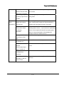
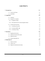
CONTENTS
1. Introduction
1-1
2. Configuration and principle
1-4
2.1. Configuration
1-4
2.2. Operation method
1-7
2.3. Compensation of compressibility
1-8
2.4. Opening and closing of valve
1-8
2.5. Gradient curve
1-8
2.6. Washing port
1-9
3. Installation and preparatory test
1-10
3.1. Inspection and installation
1-10
3.2. Mobile phase filter and vessel
1-11
3.3. Preparation of solvent
1-11
3.4. Connection of tubing
1-13
3.5. Initialization of the Gradient Pump
1-14
3.6. Connection of the frequency in-and-out terminal cable
1-15
3.7. Connection of the Vacuum Degasser & Mixer and the switches
1-15
3.8. Connection of RS232C communication cable
1-16
3.9. Connection of injector and terminal panel
1-17
3.10. Tubing connection in high pressure gradient
1-17
4. Operation
1-19
4.1. Key function
1-19
4.2. Mode Selection
1-20
4.3. Starting and Power On
1-21
4.4. Configuration
1-22
4.5. Isocratic Mode
1-25
4.6. Gradient Mode
1-27
4.7. Constant Pressure Mode
1-27
- ii -
4.8. Slave Mode
1-28
4.9. Setup Mode
1-28
4.10. Gradient Program Mode
1-32
4.11. Event Program Mode
1-34
4.12. Error Messages and their causes
1-36
5. Maintenance
1-37
5.1. Caution of use
1-37
5.2. Change of high pressure seal and conditioning
1-37
5.3. Replacement of piston plunger
1-39
5.4. Replacement and cleaning of check valve
1-40
5.5. Replacement of low pressure seal
1-40
5.6. Cleaning of flow path within pump
1-40
5.7. Supply of lubricant
1-41
5.8. Change of mobile phase filter and in-line filter
1-41
5.9. Replacement of pulse damper
1-43
5.10. Troubleshooting
1-45
5.11. Number and name of major parts
1-47
- iii -
Contents Of Figure
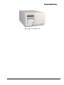
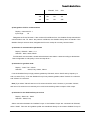
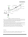
Fig 1.1. The Gradient Pump
1-3
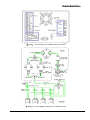
Fig 2.1. The Gradient Pump Head
1-5
Fig 2.2. The drawing of the Gradient Pump rear panel
1-6
Fig 2.3. The flow diagram drawing of the Gradient Pump
1-6
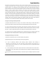
Fig 3.1. The tube connection of the washing port
1-13
Fig 3.2. The connection of frequency I/O terminal for the Gradient Pump
1-15
Fig 3.3. The connection of RS-232 cable for the Gradient Pump
1-17
Fig 3.4. The tube connection of high pressure gradient configuration for the Gradient Pump
1-18
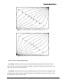
Fig 4.1. Various gradient curve and its number from 00~10
1-33
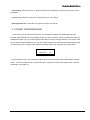
Fig 4.2. Various gradient curve and its number from 11~19
1-33
Fig 5.1. The replacement of the pressure seal
1-38
Fig 5.2. The replacement of the piston plunger
1-39
Fig 5.3. The replacement of the in-line filter
1-43
Fig 5.4. The replacement of the pulse damper
1-44
Fig 5.5. The drawing of the Gradient Pump carrier housing
1-48
Fig 5.6. The drawing of the Gradient Pump
1-49
- iv -
Contents of Table
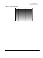
Table 4-1. Various Modes and their operation for the Gradient Pump
1-20
Table 4-2. Various events and their effects and operations
1-35
Table 4-3. Various error messages and their cause
1-36
Table 5-1. Problems, cause and fixing
1-45
-v-
Young Lin Gradient Pump
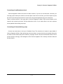
I. Introduction
The Younglin Gradient Pump was designed and fabricated as pump for high performance liquid
chromatograph requiring exact, precise solvent delivery, and has very diverse function and excellent
performance.
As the Gradient Pump controlled by microprocessor involves gradient program, gradient program of
various curves may be executed using the Gradient Pump by connecting 3 instruments or using
solenoid valve. And, the Gradient Pump has frequency output function, so it may be connected to
similar product of other company which may be operated by receiving frequency input from other
instrument.
The Gradient Pump is a precise small quantity pump, which is able to indicate constant pressure
operation and elapsed time, cumulative liquid delivery quantity, relative viscosity, etc. as well as to
realize control of various input and output and program execution with involved event program and
RS232C communication. This enables execution of operation connected with the autosampler, remote
operation using computer, etc. The Gradient Pump is equipped with cam and damper devised
especially to exert high level liquid delivery performance as well as function, and it has compression
ratio compensating function(high speed operation) to improve precision and accuracy of flow rate
simultaneously.
On the other hand, it has washing port of same type as head in pump head for durability of instrument
and uses high density fluoro-resin seal, so that life of seal is largely extended even in solvent using
buffer. It has in-line filter at outlet to prevent small particles from entering into column in order to protect
column, and is able to set upper and lower limit of pressure and flow rate. In addition, the Gradient
Pump has a function of prime/purge and key locking for convenience of user.
◎ Major features of the Gradient Pump Gradient Solvent Delivery Pump
1. Wide flow rate range and excellent flow rate linearity
2. Realization of ultra-precise liquid delivery by compression ratio compensating operation
3. Selection of 16 types of gradient curves of low pressure and high pressure by involvement of gradient
program
4. Execution status control pursuant to proceeding of time with involved event program
5. Constant pressure and constant flow selection operation
6. Indication of elapse time, accumulated flow and relative viscosity
7. Integrated configuration and convenient use
1-1
Young Lin Gradient Pump
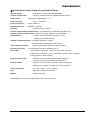
◎ Specifications of the Gradient Pump Gradient Pump
Solvent delivery
: dual plunger, pulse compensating operation
Solvent delivery mode
: isocratic, constant pressure, gradient and external input
Head volume
: cleaning part integrated 64μL x 2
Flow rate range
: 0.001 ~ 16.0ml/min
Flow rate accuracy
: 2%(at 1.0ml/min)
Maximum pressure
: 6000psi(0 ~ 420 bar)
Flushing
: Automatic every 3 minute
Solvent compressibility compensation : high speed even compensating operation type
Material of liquid contacting part : SUS316, zirconium, sapphire, ruby, UHMWPE
Gradient table
: 10 step 10 file, at least 999.9 minutes per 1 file,
16types of curves and linearity
Number of gradient channel : 3 channels (frequency is used)
4 channels (Vacuum Degasser & Mixer used)
Valve operation method
Solvent mixing ratio
Event table
: phase compensating random circulation method
: 0-100%(program execution capability 0.01%)
: at least 999.9 minutes per 1 file for 10 step 10 file, change of
gradient/event execution status, connected outside switch operation,
waiting operation, alarm program
External control input
: frequency input, instrument stop and start, marker for
event execution control, RS232C communication
External output
: RS232C, frequency output 2 channel, pressure value and
gradient curve, relative viscosity(1.0 VFS and 10mVFS)
Power requirement
: AC 110V or 220V ±10% , 50/60Hz
Size
: 297mmW x 198mmH x 495mmD
Weight
: Approximate 27kg
Specifications are subject to change without notice for improvement.
1-2
Young Lin Gradient Pump
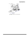
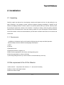
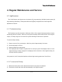
[Fig 1.1.] The Gradient Pump
1-3
Young Lin Gradient Pump
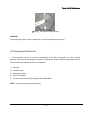
2. Configuration and principle
2.1 Configuration
The Gradient Pump is configured as follows in order to satisfy all functions and performance as a
gradient pump for HPLC.
1) Keyboard and LCD(liquid crystal display)
This enables all operations of instrument to be performed easily while confirming it through 20
characters x 2 line LCD(liquid crystal display) using keyboard. Detailed method for operation of key is
described in chapter 4.
2) Prime/purge valve
Prime/purge valve is used for providing new solvent into flow path of pump using common injector.
When using for the first time or not using for long time, insert solvent into pump head using prime/purge
valve. It is possible to change solvent using prime function of keyboard during use of instrument ; but
this function make pump operate in fine speed, so it is better to use prime/purge valve.
3) Mobile phase filter and in-line filter
Use filter in order to protect system from small particles during operation. Mobile phase filter extends life
of high pressure seal by blocking small particle entering solvent first, and in-line filter prevents small
particles generated through non-filtration in first stage and wear of seal from entering column and
shortening life of column.
4) Terminal board
This is used to connect surrounding equipment such as solenoid valve, switch, autosampler, etc. for
constant pressure gradient.
5) Pump head assembly
Pump head is a device to deliver solvent through check valve and reciprocation of piston, which is
composed of check valve, washing port and high pressure seal, washing port and low pressure seal, etc.
Pump head assembly is equipped with washing port, which may be used efficiently for using buffer
solution.
1-4
Young Lin Gradient Pump
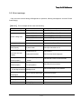
6) Main circuit panel
The panel is equipped with electronic circuit part related to microprocessor control to realize diverse
functions of the Gradient Pump.
7) Motor operation and power circuit panel
It is equipped with stepping motor control circuit and power circuit to drive motor. Stepping motor control
circuit drivers motor by micro-step, so it is possible to obtain constant motor speed even in lower noise
and lower flow rate than common control circuit.
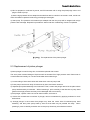
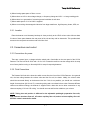
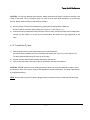
[Fig 2.1.] The Gradient Pump Head
8) Driving mechanism
This is a device to change kinetic energy generated from step motor into reciprocation motion and
transfer it to pump head. This device uses especially designed cam so that occurrence of pulse in flow
rate may be minimized even through single head pump, and is composed of stepping motor for driving,
piston carrier, carrier housing, cam location sensor, etc.
1-5
Young Lin Gradient Pump
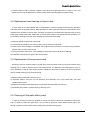
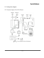
[Fig 2.2.] The drawing of the Gradient Pump rear panel
[Fig 2.3.] The flow diagram drawing of the Gradient Pump
1-6
Young Lin Gradient Pump
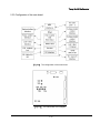
9) Flow Diagram
The flow path diagram of the Gradient Pump is illustrated on FIG 2-3. Teflon tubing is used for inlet
check valve of pump head, and SUS316 tubing is used thereafter.
10) Pulse damper
The Gradient Pump uses diaphragm damper, which reduces pulse generation of pump and serves as
the mixer for solvents in high pressure gradient. The Gradient Pump ensures precise flow rate with
compression ratio compensating program only, so that trouble is not caused for result of analysis
without damper in case gradient analysis is unnecessary or in case detector is not sensitive to pulse.
11) Pressure sensor
This is used to protect instrument from excessive pressure and realize constant pressure drive and
compressibility compensating drive by reading pressure between performances. Pressure sensor of the
Gradient Pump is designed as continuous flow path type so as to be suitable for use for HPLC.
12) Auto-flushing motor
It is used for automatic flushing the Gradient Pump inside with 20% methanol(for example) every 3
minute.
2.2 Operation method
The Gradient Pump used for liquid chromatograph requires excellent flow rate precision, flow rate
accuracy and flow rate reproducibility in order to enhance reliability of analysis data and characteristics
of detection limit. The Gradient Pump minimized generation of pulse by using diaphragm pulse damper
and especially designed cam and realizing high speed suction through microprocessor in order to
satisfy such requirement.
Diaphragm pulse damper remarkably reduces pulse generated instantly up to 90% or more from low
pressure to high pressure range with charged liquid serving as damper, and serves as mixer in gradient
analysis. Compressive property of diaphragm pulse damper improves flow rate precision by making
liquid(iso-propanol) filled inside distribute change of kinetic energy due to flow rate of mobile phase
even through compression and expansion processes. The quantity of mobile phase contacting with
pulse damper is only 1.2ml at 6000psi, which ensures that flow path is completely cleared away.
1-7
Young Lin Gradient Pump
The Gradient Pump was designed so that integrated flow rate may realize no-pulse operation using
specially designed cam. However, pulse incapable of being neglected is caused actually due to
compressibility of mobile phase proportional to pressure and elasticity of high pressure seal, so the
Gradient Pump is controlled in real time so that occurrence of pulse proportional to pressure may be
depressed. Control method of the Gradient Pump uses supervision of pressure and control of location
simultaneously, so it has advantage to improve precision and accuracy of flow rate without being
affected by range of pressure and flow rate.
2.3 Compensation of compressibility
Most of pumps for HPLC analysis are used at high pressure. However, pulse occurs in high pressure
due to compressibility of liquid and elasticity ratio of seal, so flow rate is also reduced. Occurrence of
pulse due to this reduces precision and accuracy of pump flow rate, so compensation is necessary for
this. The Gradient Pump reads actual pressure and calculates compensation value for this;
compressibility compensating operation to control angular velocity of cam with this value reduces
occurrence of pulse flow remarkably as well as improves accuracy of flow rate largely.
2.4 Opening and closing of valve
The Gradient Pump outputs valve opening and closing signal to terminal board so that gradient analysis
may be performed at low pressure as high pressure. The Gradient Pump compensates speed of valve
circulation opening and closing pursuant to location of cam in low pressure gradient as well as suction
interval is broadly distributed, so exact gradient ratio is transferred.
2.5 Gradient curve
The Gradient Pump can edit 10 gradient programs of 10 lines for gradient analysis. Gradient curve
whose shape is obtained by the following exponential equation may be selected and inputted for each
line. Gradient curve may be applied for both of gradient and flow rate. If solvent B is introduced and
mixed to solvent A at flow rate Fb and mixed solvent flows to column at flow rate Fab, concentration of
solvent B is :
c(%) = 100 x (1 - {(Fab-Fb)} over V x t)(Fb/Fab-Fb) {(1 - (Fab-Fb) over V x t)(Fb/Fab-Fb)
In the event that the above equation is actually applied, the difference between gradient ratio of
current line and gradient ratio(or flow rate) of next line is the form of the above exponential curve which
1-8
Young Lin Gradient Pump
increases and decreases.
2.6 Washing port
When using buffer solution, salts are generated on back side of high pressure seal and these
deposits wear pump seal to cause shortening of seal life, which has bad effect on pump.
Washing port enables to insert proper solvent in back side of high pressure seal to prevent salts from
being deposited and activated. Mixed solution(20% MeOH) of water and methanol is used as cleaning
solution, and life of seal is extended with lubrication action in general analysis.
1-9
Young Lin Gradient Pump
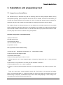
3. Installation and preparatory test
3.1 Inspection and installation
The Gradient Pump is delivered along with the following parts when being shipped. Before opening
transportation package, perform inspection for trace of shock or mistake, and if there is abnormality, do
not open the contents and inform this company of it. And, if contents are opened, perform inspection for
existence of shock in the contents and contact with this company when trace of shock is found.
The Gradient Pump is a delicate instrument, so use original box and buffer material as far as possible
when re-packing it to transport instrument. If it is impossible to use original box; wrap pump with several
layers of buffer material, and fill the bottom, top and all other sides of pump with buffer material in order
to make pump endure shock or vibration during transportation.
Standard configuration of the Gradient Pump
1) Body of instrument
2) Power source code
3) SUS316 tubing 60cm
4) 2 sets of ferrule, male nuts
5) Operation manual
Site requirement of the Gradient Pump
1) Room with 20℃ temperature with variation ± 5℃ with and 60% humidity
2) Where no direct and straight sunlight
3) Plain floor without carpet
4) Where having spare space of 20cm or more
5) Where there are 10% or less voltage change, no frequency change and 100Ω or less grounding
point
6) Where there is no generation of corrosive gas and ventilation is well done
7) Where stable power of 110 or 220V is supplied
8) Where not receiving electromagnetic induction from large transformer, high frequency heater, UPS,
etc.
There are a power input, a power transition switch and a fuse holder on the real panel of gradient
pump. The fuse specification is 1 A when uses 220V. Be sure to be careful on the power volt you use
before turning on the pump. The Gradient Pump is set at 220V during shipping. In case of using 110V,
change location of power selection switch and use.
1-10
Young Lin Gradient Pump
3.2 Mobile phase filter and vessel
Solvent vessel should be positioned at higher location than pump and not be positioned below pump,
and inlet tubing length should be as short as possible. This can minimize pressure drop caused at inlet
of pump during suction.
When using solvent having high vapor pressure as hexane, formation of air bubble is caused due to
large pressure drop in suction part in high flow rate; so particular care should be taken, and mobile
phase should be maintained after air separation, filtration and air-tightening.
Mobile phase filter of 10μm porosity is inserted into inlet tubing in order to prevent entering of small
particles. Mobile phase filter is blocked if mobile phase is bad or is used for long time, it is necessary to
clean or change filter in this case.
3.3 Preparation of solvent
Proper solvent prevents various problems caused during actual analysis. Solvent gas removal and
filtration are necessary because they have great effect on result of analysis and maintenance of
instrument.
1) Degassing
Solvent gas removal is performed in order to remove gas such as nitrogen or oxygen contained in
mobile phase. Contained gas should be removed by air separation before mobile phase is used or while
mobile phase is used, and the most practical technology for air separation is to insert helium into
solvent.
Helium is easily separated from HPLC solvent, so other gases contained in solvent may be easily
removed due to diffusion of helium gas.
Filtration of solvent using vacuum pump is not a effective method than helium separation, but it is said
to be a helpful method. When separating air using helium, insert it severely for 10 or 15 minutes
before using solvent and maintain proper injection status during use. If air is separated from solvent
before use, gas in the atmosphere is melted into mobile phase within 4 hours. Helium purity used
should be 99.9% standard laboratory grade.
When mixing organic solvent such as methanol or acetonitrile into water, this mixture contains very
small quantity of gas as compared to the quantity of pure composition; so it has more strong tendency
to discharge gas. Back pressure regulator attached to outlet of detector prevents formation of noise in
1-11
Young Lin Gradient Pump
base line due to air bubble, and mobile phase vessel should be pressurized under 2-3psi pressure with
helium if it is desired to reduce gas discharge due to solvent mixing.
2) Filtration
Solvent should be necessarily filtered through 0.45μm or less filtering membrane before use. Removal
of small particles is necessary to compensate reliable operation of piston seal, and is necessary
measure for reliability of other components in liquid chromatograph.
Filtration process is necessary after mixing of solvent, and is more necessary in case of buffer to which
un-dissolved impurities are source of deposits. After filtration, solvent should be keep in air-tight bottle
from which small particles are removed; once solvent has been filtered, it is not necessary to filter this
solvent everyday unless reaction produce bacteria or indissoluble material occurs. If solvent is kept in
storage vessel for more than one week, it is desired to filter it again before use.
3) Solvent effect on the instrument
All parts of the Gradient Pump contacting with mobile phase is manufactured from 316 stainless steel,
ruby, sapphire, zirconium, or fluorine carbon polymer. Most of these materials are sensitive to chloride,
and it is desired to avoid use of solvent which contains even small quantity of chloride. Main solvents
which should be avoided especially are as follows.
Aqua Regia
Hydrochloric Acid(HCL) (20%)
Bromine
HCL (37%)
Chlorine Anhydrous
HCL (50%)
Copper Chloride
HCL (20%)
Ferric Chloride
HCL (75%)
Ferrous Chloride
Hydrofluorsilicic Acid (20%)
Freon 12
Hydrogen Peroxide
Guanidine
Lodine
Hydrochloride (6M)
Mercuric Chloride
Hydrobromic (20%)
(Dilute Solution)
In addition, it should be avoided to leave chloroform, carbon tetrachloride, etc. in instrument for long
time, and use of ammonium hydroxide should be avoided because it has effect on stator and rotor of
injector even though it has no effect on pump. When not using it for long time, keep it with iso-propanol
filled with in flow path.
1-12
Young Lin Gradient Pump
4) Measures when not uses for long time
① Prepare iso-propanol for analysis.
② Open prime/purge pump and suck iso-propanol of at least 50ml into instrument.
③ Separate outlet tubing of pump.
④ Press out iso-propanol sucked into syringe in prime/purge valve and discharge at least 5ml into
outlet of in-line filter.
⑤ Separate mobile phase filter assembly and block discharge hole and suction hole with cap.
3.4 Connection of tubing
The following tubing and fitting are used as standard size in flow path of the Gradient Pump.
Material
OD
ID
fitting size(UNF size)
1) SUS316
1/16"
0.02"
10-32
2) Teflon
1/16"
1/32"
1/4-28(plain bottom)
3) Teflon
1/8"
1/16"
1/4-28(plain bottom)
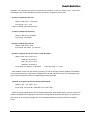
[Fig 3.1.] The tube connection of the washing port
Item 1) is used for tubing from outlet check valve to in-line filter and injector, item 2) is used for
washing port, and item 3) is used for tubing connected to mobile phase filter and inlet check valve
housing. Standard of tubing may be used by changing it with proper one depending on flow rate and
pressure used.
1-13
Young Lin Gradient Pump
Generally, in case it is used at low flow rate or delivery volume should be small, one of narrow inner
diameter may be used ; but it is recommended to use proper size because it may be cause to reduction
of accuracy of flow rate due to large pressure difference in suction process of solvent in high flow rate.
On the other hand, the standard of 1) is used for connection of the Gradient Pump and injector for
analysis, and tubing of 0.01" inner diameter is used on the back side of injector. The cut surface of
tubing should be cut at right angle without dust, tube should not be contracted, and middle inner
diameter shall not be blocked.
In order to cut stainless steel tubing, tubing cutter should be used, plastic tubing cutter or shaving
cutter should be used for teflon and similar material of tubing, and the surface should be clean and have
no crumbling.
Connect tubing of washing port with 1/4-28 fitting as figure 6, inject 20% methanol of 10ml to 20ml
into outlet of bottom side using common syringe to make methanol flow out, and then make piston
cleaned automatically using natural load drop. Because cleaning liquid is much consumed due to
increase of cleaning liquid flow rate if drop difference is large, it is desired to reduce consumption of
cleaning liquid by reducing drop difference.
In case of re-using cleaning solution having come out, check change period by inspecting base
concentration with litmus test paper and prevent contamination of cleaning part by replacing it with very
clean new solution.
3.5 Initialization of the Gradient Pump
When using pump for the first time, initialize it through the following process in order to clean flow
path and condition high pressure seal. This process is necessary in case instrument is installed newly or
is not used for long time.
1) Preparation of iso-propanol for analysis.
2) Remove residual air bubble within instrument by turning prime/purge valve in counter clockwise and
loading iso-propanol of at least 50ml with injector.
3) Separate pump outlet tubing.
4) Press the sucked iso-propanol into injector with prime/purge valve and discharge more than 5ml to
outlet of in-line filter.
5) Operate pump with instrument outlet open for 2-3 hours at 0.2ml/min flow rate and for 1 hour at
1.0ml/min flow rate using iso-propanol.
6) Perform process of 2) using solvent which is desired to be used.
1-14
Young Lin Gradient Pump
7) Remove inside residual iso-propanol by operating it at 1ml/min flow rate for 30 minutes with
instrument outlet open.
8) Form flow path by connecting injector, column, and detector tubing mutually.
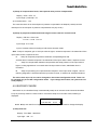
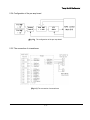
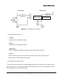
[Fig 3.2.] The connection of frequency I/O terminal for the Gradient Pump
3.6 Connection of the frequency in-and-out terminal cable
The Gradient Pump has frequency input function to be used as slave pump by connecting The
Gradient Pump can perform high pressure gradient by connection with other manufacturer's pump
which is able to receive 5V TTL input because setting of frequency output range proportional to flow rate
is possible. In order to connect it to the product of other company, it is necessary to take care in
electrical connection. Please contact the manufacturer for details. In case of performing gradient using
the Gradient Pump, frequency range of slave, proportional flow rate, and related designation value are
described in detail in chapter 4.
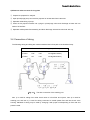
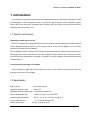
3.7 Connection of the Vacuum Degasser & Mixer
The Gradient Pump has terminal board which is able to connect solenoid valve and switch in order to
perform low pressure gradient. Solenoid valve and switch may be connected for 12V, and output is
disconnected when on if it is connected with 0V.
The Gradient Pump is configured suitably for three solvents gradient generally, but gradient ratio
for %D solution is output to SW1 terminal board in order to make four solution gradient possible. This is
1-15
Young Lin Gradient Pump
operated only if sum of gradient ratios of three solutions is less than 100%.
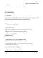
12V
12V solenoid valve and switch power source
VALVE1
gradient ratio A output
VALVE2
gradient ratio B output
VALVE3
gradient ratio C output
0V
Valve or switch output grounding
12V
12V solenoid valve and switch power source
SW1
gradient ratio D output or switch 1 output
SW2
Switch 2 output
SW3
Switch 3 output
Gradient
12V
Black line
BNC
Pump
Valve A
Red line
Cable &
Side
Valve B
Yellow line
CONNECTOR
Valve C
Green line
SW1
White line
Side
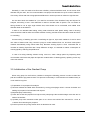
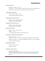
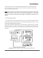
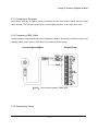
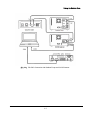
3.8 Connection of RS232C communication cable
The Gradient Pump has communication function so as to perform high pressure gradient by
connecting up to 3 sets of the Gradient Pump, and is able to perform major function of Gradient Pump
using RS232C with computer. Command is described in chapter 4. Communication cable is connected
by taking RX and TX as chain loop type. That is, when connecting each pump, closed loop is made by
connecting TX and RX; when connecting it with computer , one TX output among each pump is
connected to RX pin and RX pin is connected to computer TX pin. And, in case of using computer,
Gradient Pump should be in slave mode ; in case of using Gradient Pump by connecting each other,
there should be only one master pump. More detailed content for this is described in chapter 4.
1-16
Young Lin Gradient Pump
[Fig 3.3.] The connection of RS-232 cable for the Gradient Pump
3.9 Connection of injector and terminal panel
START, STOP, MARK-OUT and HOLD of the terminal panel are used for automatic repetitive analysis
with the autosampler.
START
: operates instrument and perform gradient program and event program together in
gradient mode
STOP
: stops instrument
MARK-IN
: can control event program during gradient with this input condition.
MARK-OUT
: can control output with event program during gradient.
HOLD
: in case the Gradient Pump is started and prepared to perform analysis, HOLD output
is disconnected. Using this condition, waiting status of objective instrument may be induced.
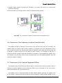
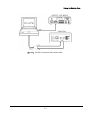
3.10 Tubing connection in high pressure gradient
In case of performing high pressure gradient using the Gradient Pump, it is desired to change tubing
connection in order to make solvent mixed well.
At this time, pump outlet used as slave should be connected to tubing to enter damper of inside of
instrument in master side using TEE or CROSS.
1-17
Young Lin Gradient Pump
[Fig 3.4.] The tube connection of high pressure gradient configuration for the Gradient Pump
1-18
Young Lin Gradient Pump
4. Operation
4.1 Key function
The keyboard of the Gradient Pump is consisted of function keys and number keys. The function keys
are as follows and each function is described.
1) START/STOP : Used for starting or stopping the run of Gradient Pump which is operation on Run
Mode. On Isocratic or Constant Pressure Mode, press 2 times, stops the Gradient Pump and press 1
time more, starts the Gradient Pump. On Gradient Mode, press 1 time turns to standby state. One more
time press starts gradient run of the Gradient Pump and then 2 times press during gradient run stops
the Gradient Pump.
2) CLR/SCL : Used for clear the setting value or scrolling the selection value. Also used for clearing the
limit for pressure or flow which are already set. Also used for change the LCD display of the Gradient
Pump.
3) ▲, ▼ : Used for moving a cursor to display during Isocratic Mode and Constant Pressure Mode and
for moving a cursor to editing line during Program Event Mode and Gradient Mode. Also used for
moving editing line up and down.
4) ENTER : Used for input of value and parameter scrolled.
5) PURGE : Used for quick removal and change of solvent in the Gradient Pump. Works only when
pressing the key during the pump stops while the LCD displays as follows. When pressing the key, the
Gradient Pump runs at high speed so be sure to open the prime/purge valve.
PRIME / PURGE !!
Execute..........
4) ● : Used for recalling another file number during Gradient Mode and Event Mode. Also used for input
of a decimal point when input values.
1-19
Young Lin Gradient Pump
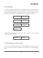
4.2 Mode Selection
There are two modes selectable, Editing Mode and Run Mode on the Gradient Pump operation. Each
Mode is selected by pressing the corresponding operation keys and then Enter key. For example, if
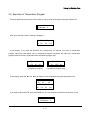
press the GRAD. key, following message is displayed and the mode is selected by pressing the ENTER
key.
PROGRAM GRAD. FILE
Mode Select? Yes
If press the CLR/SCR key following pressing the GRAD. Key, following display is appeared and by
pressing the ENTER key, then changing mode is cancelled and returned to the first mode.
PROGRAM GRAD. FILE
Mode Select? No
However, Run Mode is always effective during Editing Mode. All parameter settings work immediately
and are not removed after re-starting the Gradient Pump by switching on/off.
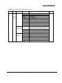
[Table 4.1.] Various Modes and their operation for the Gradient Pump
Mode
ISOCRATIC
GRADIENT
Description
Isocratic Mode with constant
flow and constant mixing time
Gradient Mode with gradient
and event file
Mode
CONFIGURATION
Description
Input the values for
configuration of the pump
Input of calibration factors for
SET UP
display of pressure limit, flow
rate limit and relative viscosity
CONSTANT Maintain constant pressure
PROGRAM
Edit the gradient file by each
PRESSURE inside pump by adjusting flow
GRADIENT
line
SYSTEM
SLAVE
Set as slave Mode by
frequency in-and-out and
serial communication
PROGRAM
EVENT
1-20
Making or editing a file for
gradient Mode condition
according to elapsed time
Young Lin Gradient Pump
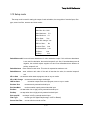
4.3 Starting and Power On
On switching on the pump, following messages are displayed in sequence and the self-diagnostics is
done.
YOUNGLIN SP930D
Solvent Delivery Pump
YOUNGLIN
INSTRUMENT
If previous values saved at SRAM are not valid or press the Enter key, the edited values are initialized
and set-up as defaults. In case SRAM is in defect,
VER1.10 SELF TEST
CMOS Backup Fail!
In case the operator press the Enter key,
VER1.10 SELF TEST
CMOS Backup Clear!
On initializing,
VER1.10 SELF TEST
Data Initialize ..
In case no malfunctions or after initialization,
VER1.10 SELF TEST
OK!
If you turn on the power of the pump with pressing Config. Button, the QC set up is on processing and
the pump will ask you of maximum flow, maximum pressure and, maximum motor frequency, etc..
VER1.10 SELF TEST
Max. Flow: 16ml/min
After input of all these values, the calculated pump head volume is displayed for short a while and
the pump is operated accordingly. Therefore, be sure to confirm the pump head volume and ask us if
the volume is different from the one that you purchased.
1-21
Young Lin Gradient Pump
If the pump is used as a master pump and uses RS-232C for gradient Mode, the system checks
connection for communication with a slave pump.
Serial Slave Check
........ Accepted.
Serial Link Check
Out of Time.
After initialization is finished, the pump is run at isocratic mode. If the pump was set up as a slave, it
will be run as a slave.
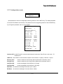
4.4 CONFIGURATION
The values on the configuration are already factory set. Understand clearly what each value means.
The default values should not be changed without special reason. On the configuration, there are the
values for maximum flow rate, gradient Mode with two or more pumps and calibration factor for constant
flow rate or constant mixing rate operation. Meanwhile, an operator can not change the values for the
pump itself where no cursor is occurred.
As for special reason, an operator can change by pressing the CONFIG key just after switching on but
ask us for details.
The configuration can be seen after passing identification by input of password. If want to change the
password, press the CONFIG key and then the CLEAR key and input new password you want. The
default password is 9 3 0 ..
Password?
[****]
After passing identification, an operator can input the values for the pump configuration itself in
sequence. The values already set-up are replacements when the SRAM backup fails. If change the
values, they affect the Gradient Pump operation, so be sure to clearly understand what they mean.
1) Gradient Channel Selection on the Slave Mode
Display
: %A
Selection ; %A, %B, %C
When more than 2 Gradient Pumps are used for high pressure gradient operation. Each pump should
be set up as a master and slaves. Following is instructions how to set up each pump.
1-22
Young Lin Gradient Pump
SP930D CH1
CH2
%A
%A
%B
%C
%B
%B
%A
%C
%C
%C
%A
%B
2) Designation of ID for communication
Display : Instrument ID : 1
Input range :
1-8
Designate the ID via RS-232C. If the received ID is different from, the Gradient Pump transmits the
communication over TX. Also if the protocol is different, the Gradient Pump does not handle. If the
Gradient Pump is set as a slave, designate the ID not to overlap for correctly communication.
3) Selection of communication parameters
Display : RS232C : 9600, n, 8, 1
Selection : 9600, 19200, 38400
For RS-232C communication, should select the baud rate. 9600 or 19200 according to desired rate.
Date configuration is 8 bit, parity is none and stop bit is 1.
4) Selection for gradient mode
Display : Grad. Tool : Valve4
Selection
: Serial, Freq, Valve3, Valve4
If run the Gradient Pump in high pressure gradient by RS-232C, select “Serial” and by frequency in
and out, select “Freq.”. If run the Gradient Pump in low pressure gradient, select "Valve3" for 3 solvents
and "Valve4" for 4 solvents.
Note) If you select "Valve3" total sum of % solvent should be 100%. However, if you select "Valve4",
total sum of % solvent is not necessary to be 100% and remaining value is output to SW1 output.
5) Selection for the Gradient Pump as a slave
Display : Slave Link : Serial
Selection : Serial, Freq.
Select connection between the Gradient Pumps. If the Gradient Pumps are connected via RS-232C,
select "Serial". Flow rate and gradient profile are transferred directly to the master Gradient Pump via
1-23
Young Lin Gradient Pump
RS-232C. If the Gradient Pumps are connected via Frequency in and out, select "Freq.". Flow rate is
transferred to the master Gradient Pump after conversion of frequency to flow rate.
6) Setup of maximum flow rate
Display : Max. Flow : 16.0 ml/min
Input range : .001 ~ 16.0
If want to change, input desired value.
7) Setup of maximum frequency
Display : Max. Freq.: 38400Hz
Input range : 320-64000
8) Setup of maximum pressure
Display : Max. Pres.: 9000
Input range : 80-16000 (for psi unit)
9) Setup of frequency and flow rate for external output
Display : Max. Freq. Conv. CH 1 :
40000 Hz- 20.0 ml/min
Max. Freq. Conv. CH 2 :
40000 Hz- 20.0 ml/min
Input range for frequency : 320-64000
Flow rate range : 0.1 - 200
If the Gradient Pumps are connected by frequency in and out for high pressure gradient, the Gradient
Pump outputs frequency in proportion to gradient ratio via DIN output on the rear of the Gradient Pump.
Input maximum frequency and its corresponding maximum flow rate.
10) Setup of origin point at Even Compensation Mode
Display : DPL 90 DPR 270
Input range : DPL<82-98>, DPR<DPL+176 - DPL+184>
If want to change original point at Even Compensation Mode, input desired value. However, check real
pressure change before changing the value as the change affects operation. Be careful not to input any
value which is not checked or tested. DPL is for left head and DPR is for right head of the Gradient
Pump.
1-24
Young Lin Gradient Pump
11) Setup of compensation factor, intercept and valve position compensation
Display : CFB: 4 CFV: 18
Input range 1) Intercept 1-16
2) Correction factor : 1-32
The correction factor is for the end point of pressure compensation at 2000psi(=140bar) and the
intercept is for the end point of pressure compensation at 0 psi(= 0 bar).
12) Setup of proportional differential and integral control value for isocratic mode
Display : PID Set > Gain=0.36
P=0.24 I=4.80 D=0.12
Input range : 0.01-9.99
Input of constant values according to PID trace at isocratic mode.
Gain : Setup for response gain. If the input value is higher, excessive response is increased and if the
input value is lower, response is slow.
P
: Setup for response proportional coefficient corresponding flow rate.
As Gain does, Excessive response is increased and if the input value is lower, response is slow.
I
: Setup for compensation between real pressure and setup pressure. If the input value is
higher, hunting appearance is occurred and if the input value is lower, stabilization time is
increased.
D
: Setup for preventing from rapid excessive response. If the input value is higher , time for
reaching integration is increased and the input value is lower, is sensitive to external turbulence.
The values from 10) to 12) can not be changed on the normal Configuration mode. These can
be changed only on the QC configuration mode. If you change these value, the system can not
work properly.
4.5 ISOCRATIC MODE
After switch on, the Gradient Pump is automatically setup as an isocratic mode unless the Gradient
Pump is previously used for a slave mode. If succeed to setup as an isocratic mode, following is
displayed.
Flow Rate:.000ml/min
%A:100 %B:
0 %C:
0
▲and ▼keys are used for moving lines and the [CLR/SCL] key is used for change the display.
1) Setup flow rate
Display : Flow Rate: .000ml/min
Input rage : .000 - 16
1-25
Young Lin Gradient Pump
2) Setup solvent ratio
Display : %A: 100 %B: 0 %C: 0
Input range : 0 ~ 100 for all channels. The total sum should be 100 if use 3 solvents but can
be less than 100 if use 4 channels. The difference is output via SW1 terminal.
3) Display of current pressure
Display : Pressure : 0 psi (or 0.0bar)
Current pressure is displayed as psi or bar.
4) Display of maximum pressure limit
Display : Hi. Limit : 6000psi(or 420.0 bar)
Maximum pressure limit is displayed.
5) Display of minimum pressure unit
Display : Low Limit : 0psi(or 0.0 bar)
Minimum pressure limit is displayed.
6) Terminal switch on/off
Display : S1:Off
S2:Off
S3:Off
Selection : On, Off
S1 is used for display of gradient rate of channel 4 if used.
7) Display of accumulated volume and pressure
Display : Volume Acc.
0.0 μ l
Input range : The input of 0 ~ 100.0 can be possible when the Gradient Pump is stopped.
When the unit is set as μ l, input 100.0 then changed to the unit of 0.1 ml. The accumulated
volume is displayed upto 999.9Lit.
8) Elapsed time and input
Display : Lapse Time 0.0 min
Input range : 0-999.9
9) Display of relative viscosity
Display : Viscosity Ratio N/A
Displays the relative viscosity calculated by reference value and current pressure and flow
rate. If the viscosity is over range of 0.01 ~ 9.9 or the Gradient Pump is stopped, N/A is
displayed.
1-26
Young Lin Gradient Pump
4.6 GRADIENT MODE
The Gradient Mode is used for running gradient operation of the Gradient Pump. The gradient is run
as per a gradient file and an event program file. If select this mode to run, the Gradient Pump ask you of
followings.
1) Input of the gradient file number to run
Display
Grad. File No.: 0
Input range
0-19
2) Input of repetition START number for a gradient file
Display
Max. Chain No.?
Input range
1-999
3) Input of the event file number to run
Display
Event File No.? 0
Input range
0-19
After input all of above values, the Gradient Pump runs for gradient operation. At the gradient mode,
key and its operation is as follows. Press the CLR/SCR, one of following displays will be displayed.
Display (1)
ID
01
0.1
Display (2)
Time
Flow
Pres.
1.00 1930
Time
1.00
100
Display (3)
%A
%B %C
CV
0
0 05
F#
01
Time S1 S2
0.0 on off
S3
off
If press the • key, open a new gradient file and an event program file to edit and also set up the
repetition run number.
Consecutive pressure of the START/STOP key work as follows.
At Standby status, one press of the key changes to initial status.
At Initial status, one press of the key changes to run status for gradient
At Run status, one press of the key, warning is appeared for "Now Gradient Mode" and 2
consecutive pressures of the key changes to initial status.
4.7 CONSTANT PRESSURE MODE
The mode runs the Gradient Pump by maintaining constant pressure while the isocratic mode runs by
maintaining constant flow rate. So input the pressure that you want to operate and upper and lower
range of flow rate, then current flow rate will be displayed. Other factors are same with those of the
isocratic mode.
1-27
Young Lin Gradient Pump
1) Input of the pressure that want to operate
Display
Pres. Set : 1000psi
Input range
0 ~ maximum pressure
The Gradient Pump adjust flow rate to maintain the input pressure.
2) Display of current flow rate
Display
Act. Flow 1.00ml/min
Current flow rate is displayed
3) Display of upper limit of flow rate
Display
Hi. Limit : 10.0ml/min
4) Display of lower limit of flow rate
Display
Low Limit: 0.00ml/min
4.8 SLAVE MODE
The mode run the Gradient Pump by input of flow rate from the master Gradient Pump via serial or
frequency in and out. Pressure of the CLR/SCl key shows current pressure and flow rate.
SYSTEM SLAVE
Serial Input HPG %B
If the pump is on the Slave mode, it can not be controlled by keyboard. Only controlled by master
pump or Autochro-2000(or Autochro-3000) software.
4.9 SETUP MODE
If select the setup mode, first you can see the selection of key lock function. If select the key lock by
pressing Yes, shows you the mode which is currently running. If the key is locked, have to return to the
current run mode and can not use key operation further until the key lock is unlocked. Press 9 3 0 •
sequentially for unlock.
Key Lock : No
1-28
Young Lin Gradient Pump
If you select the Key Lock to No, you can see the setup menu as below.
1) Display of upper and lower limit of pressure
Display
* Pressure Limit *
High : 6000psi
* Pressure Limit *
Low :
0psi
The maximum value of upper pressure limit should be inputted within the maximum pressure limit of
system(6000psi) which are already setup and larger by 10 psi(or 0.7 bar) than the upper limit of
pressure. The minimum value of lower limit of pressure should be lower by 10 than the upper limit of
pressure. If input "0" it means no lower limit you apply.
In case current pressure is higher than maximum upper pressure, the Gradient Pump immediately
stops, so if you want to clear the limit, pressure the key CLR/SCR.
2) Input of upper and lower limit of flow rate
Display
* Flow Rate Limit *
High : 10.0ml/min
* Flow Rate Limit *
Low : .001ml/min
Input range : The upper limit is lower than maximum flow rate and the lower limit is 0. Input of
lower limit to "0" means no application of lower limit.
In case current flow rate is higher than maximum upper limit, the Gradient Pump immediately stops, so
if you want to clear the limit, pressure the key CLR/SCR. Input of "0" means no application of flow rate.
1-29
Young Lin Gradient Pump
3) Input of Viscosity Conversion Value
Display
Ref.Viscosity : 1.00
Test Flow:1.00ml/min
Ref.Viscosity : 1.00
Disp.Pres:
1000 psi
Input range : 0.01 ~ 9.99.
Reference viscosity can be within 0.01-9.99, Test flow can be within .001-100.0mL/min and Display
pressure at Test flow can be setup within 10-9000 psi(0.7-630 bar). At Isocratic and Constant Pressure
Mode, the value will be displayed by following calculation.
Flow rate at input x Current pressure
Relative Viscosity Ratio = Viscosity input x ----------------------------------------------------Pressure at input x Current pressure
4) Change of Pressure Unit
Display
Pressure Unit : psi
Selection
psi, bar
Select the unit you want to display
5) Selection for Even Compensation
Display
Even Compensate : Yes
Selection
Yes, No
If select "Yes", the Gradient Pump runs by compensated flow rate which is compensated by even
compensation value and current pressure.
6) Selection for Even Compensation Mode
Display
Pressure Trace : No
Selection
Yes, No
Selection of "Yes", Gradient Pump runs by pressure compensation.
7) Input of Value for Flow Rate Calibration
Display
Flow Calib. : 1.00
Input range 0.80 - 1.25
Calibrate the difference between real flow rate and setup flow rate.
1-30
Young Lin Gradient Pump
8) Change of Pressure Display Scale
Display
Pressure Scale : 1.00
Input range
0.5-2.0
In case pressure displayed is not same with real pressure, input the difference value for calibration.
9) Selection of DA Voltage Output
Display
Chart out : Pressure
Selection
Pres., %A, %B, %C, Flow, Visco, Curve, SL-CH1, SL-CH2
Output of pressure, mixing rate, flow rate, viscosity, gradient curve and frequency ratio between
channel 1 and channel 2 via analog output terminal.
10) Setup of DA Voltage Output Offset
Display
Chart Offset : 420 (0-1000)
Input range 0 - 9999
Input of offset value for DA voltage output
11) Setup of DA Voltage Output Gain
Display
Chart Scale: 1.00
Input range 0.01 - 9.99
Input gain value of DA output
12) Change of Zero Point for Pressure
Display
Pressure Zero : No
Input range
Yes, No
Changes the zero point of current pressure output. As the offset value of a pressure sensor can be
largely changed by temperature and pressure, recommended to re-setup the zero offset after drop
pressure.
13) Setup of Auto-flushing
Display
Rinse Operate: Yes
Selection
Yes, No
Select "Yes" if you want to clean the Gradient Pump inside by an auto-flushing pump built-in inside. It
flushes every 3 minutes.
1-31
Young Lin Gradient Pump
4.10 GRADIENT PROGRAM MODE
Creates and edits a file(s) for gradient operation. As the mode, the Gradient Pump asks you the
number of a file and if you want to create or edit a file. Can select any file number from 0 to 20.
Grad. Table No.: 0
Clear Table
: No
When clears a file, flow rate is set to 0, %A mixing rate to 100%, and other channels' mixing rate
also set to 0%. Other lines except the first line are cleared. Open another file during editing mode, press
the • key then returns to the above display. When open a file, following table are displayed on the LCD
screen. It is one of examples, if want to create a new file, please clear.
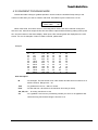
Example
ID
00
01
02
03
04
05
06
07
08
09
10
11
Time
init
0.1
12.1
30.5
40.2
100.0
200.8
300.0
500.0
600.0
700.8
999.3
Flow %A
%B
%C
CV
1.00 100
1.10 60
1.50 40
2.00 30
2.00 20
1.50 10
2.00
0
1.00
0
1.00 50
1.50 10
2.00
0
1.00 100
0
40
40
40
40
40
40
30
50
40
40
0
0
0
20
30
40
50
60
70
0
50
60
0
*
05
06
06
06
06
13
13
15
06
13
19
Item description
ID
: for two digits. The first number is for a file number and the second number is for a
edit line number. Range is 00 ~ 39.
Time
: for gradient time from 0 ~ 999.9 in minute
Flow
: for flow rate from .001ml/min to the maximum flow rate you setup.
%A, %B, %C : for mixing rate from 0 to 100
CV
: for a gradient curve from any of following number you want. CV is applied to flow
rate and mixing rate as well. Range is from 00 to 19.
1-32
Young Lin Gradient Pump
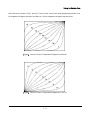
[Fig 4.1.] Various gradient curve and its number from 00 ~ 10.
[Fig 4.2.]Various gradient curve and its number from 11 ~ 19.
How to create or edit the gradient table
Line editing : When the cursor is on the ID, press the ENTER key to start input of one line and if
return the cursor to the ID, input of the line is finished. If change the operation mode during input, the
input on the line is not saved nor effected.
Line adding : When the cursor on the time, please input any time you want but not overlapped. After
finished the input, the lines are automatically sorted by time. Please do not input over 40 lines. If input
by mistake over 40 lines, it will not work.
1-33
Young Lin Gradient Pump
Line deleting : When the cursor on the ID, pressure the CLR/SCR key. However the first line will not
be deleted.
Line moving : When the cursor on the ID, press the ▲ or the ▼key.
Opening another file : Press the • key when the cursor is on the ID.
4.11 EVENT PROGRAM MODE
At the mode, you can edit a event file which can change the gradient mode parameters and the
external output parameters for the gradient file that you want to change. When you select the mode, the
Gradient Pump ask you if you want the file number that you want to change and also if you want to clear
the file. Files can be selected from 0 to 20. The event program file is same with the gradient program file
to create, edit or save. If some of file numbers are being used or run, the file(s) can not be edited.
Event File No.: 0
Clear File
: No
Key operation for clear, edit, create and edit for file and line is same with that of the gradient program
mode. Press the CLR/SCR key to select each item. The items for the event program at the mode are
described on the Table 4.2.
1-34
Young Lin Gradient Pump
[Table 4.2.] Various events and their effects and operations.
Event
Operation
Maintains the first gradient program at initial status of
waiting events.
Init
Grad
Start
Stop
Start
Event
Starts the first gradient program of waiting events
Stops the Gradient Pump during running.
Starts an event program that is on waiting.
Stops event program(s) which is waiting after the
line(However "Event Resume" is not terminated at the
command for recovering event runs already done.
Stop
SW1
Changes the SW1 terminal output of On, Off or Pulse(200m/s)
according to your selection.
SW2
Changes the SW2 terminal output of On, Off or Pulse(200m/s)
according to your selection.
SW3
Changes the SW3 terminal output of On, Off or Pulse(200m/s)
according to your selection.
Mk-out
Changes the mark out terminal output of On, Off or Pulse(200m/s)
according to your selection.
Alarm
Changes alarms by On, Off or Pulse(200mS) according to your
selection.
Grad. #
Select a gradient file(0 ~ 19) number to run for event program.
Event #
Select an event file(0 ~ 19) number to run for event program.
The event program is very useful for repetition run of a gradient or an event program. Please refer to
following example to create or edit an event program that you want to run.
An example for the event program : After 100 minutes elapse, event file No 1. and gradient file No 2
are subsequently executed.
As for the item "Mark", it can be N/A or Wait. If you select "Wait" the event is started when received
the external input such as load of RH7725 manual injector or any other input to designated terminal.
The waiting events are executed as per external input not by time. However the waiting events which
need same mark out input, the events are executed subsequently. If re-start the event program, all
waiting event are neglected.
Event file number 0
ID
Time
Event
Action
Mark
Explanation
00
INIT
Grad.
Start
N/A
Starts the gradient mode
01
10.00
SW1
On
Wait
Outputs a pulse via SW1 when received the mark
On
Wait
Outputs a pulse via SW2 when received the mark
Outputs a puls via mark out1
02
10.10
SW2
03
15.00
Mk-out Pulse
N/A
04
20.00
Event# 1
N/A
Changes the event file number to 1
05
20.10
Grad.# 2
N/A
Changes the gradient file number to 2
N/A
Executes the event table number 01
06
100.00 Event
Start
1-35
Young Lin Gradient Pump
Event file number 01
ID
Time
Event Action
Mark
Explanation
10
INIT
Grad. Start
N/A
Starts the gradient program mode
11
100.00
Event Start
N/A
Executes event table number 01
Note 1) When the mark out terminal is connected to the mark in terminal, you can switch the SW1 and
the SW2 on simultaneously. With this function, you can operate simultaneous operation for two external
valves or other instruments.
Note 2) However, please be careful when use 4 channel valve which is used for the mixing rate of the
channel 4. They can not be used together.
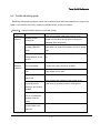
4.12 Error messages and their causes
Following messages are occurred by error during use or by external input. Table 4.3 describes various
error messages and their causes.
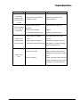
[Table 4.3.] Various error messages and their cause.
Error message
High pressure limit
Low pressure limit
Flow upper limit
Flow lower limit
Max. flow limit
Communication error
Max. frequency Limit
Unbalanced limit
Cause
When current pressure is higher than the upper limit at the
isocratic, the gradient or the slave mode.
When current pressure is maintained for 30 seconds lower
than the lower limit at the isocratic, the gradient or the slave
When flow current rate pressure is maintained for 30 seconds
higher than the upper limit at the isocratic or the slave mode.
When flow rate is lower than the limit at the isocratic or the
When flow rate is higher that the limit at the gradient mode.
When slave pump is stopped due to protection or When any
errors are occurred during communication for decoding,
transmission or receipt.
When frequency output is over than the range.
When pump head is moving unstable due to air or check
Remote start
When start input is from a terminal or RS-232C.
Remote stop
When stop input is from a terminal or RS-232C.
1-36
Young Lin Gradient Pump
5. Maintenance
In the event that problem occurs or it is necessary to change part due to wear of seal in using The
Gradient Pump, perform maintenance for instrument by referring to the following items.
5.1 Caution of use
In order to protect instrument, take care for the following items in using it.
1) After using solvent with sediment such as buffer solution, replace solvent with pure water at first and
then methanol or iso-propanol and make it flow for 30 minutes using each solvent at 1.0ml/min flow
rate.
2) Do not use solvent to corrode stainless steel material which is less than pH 2.3.
3) Do not install instrument where corrosive gas is generated or where there is carpet on floor.
4) Do not change flow rate rapidly in order to prevent from wrong operation of instrument, damage to
column and damage to damper.
5) Do not operate instrument with excessive force.
5.2 Change of high pressure seal and conditioning
If instrument is used for long time, high pressure seal is worn out to produce leakage of solution. In
this case, after replacing it with new seal, it is necessary to condition it in order to make seal be used for
long time at high pressure. Change and condition high pressure seal in the following method. In case
instrument is used for the first time after purchasing, it is desired to perform training and it is better to
change all seals of both head when change seal due to long use. Leaked liquid flows out through
washing port.
Change of high pressure seal
1) Loosen tubing of inlet check valve and outlet check valve of pump head.
2) Press pump head to main body of instrument with hand, and loosen head nut.
3) Separate pump head assembly from instrument. At this time, screen and plunger are left at the
place where pump head assembly was loosened. When loosening it, pull it carefully in pump head
guide direction and take care not to damage plunger.
4) If backup washer in back side of pump head is pulled out, low pressure seal assembly appears. Use
seal insertion/removal tool to separate low pressure seal assembly. Then, high pressure seal appears
inside of head.
1-37
Young Lin Gradient Pump
[Fig 5.1.] The replacement of the high pressure seal
5) Remove worn seal with seal insertion/removal tool and insert new high pressure seal prepared at that
place using seal insertion/removal tool in the same manner. Direction of seal should be such that the
direction to see O-ring is toward front of head. Be careful not to change direction.
6) Insert low pressure seal assembly and backup washer.
7) Arrange pump head so that plunger left at the place where it is loosened be inserted into center hole
of pump head assembly, and then press pump head to main body by inserting pump head by hand.
When pressing it, press it carefully so that pump head may be maintained horizontal.
8) Tighten head nut in pressed condition. Tighten it so that left side and light side may be same, and
tighten it until it is tightened no more by hand while confirming status of tightening finally.
9) Change high pressure seal by applying the process of 1 to 8 to pump head of opposite side.
Conditioning
1) Prepare organic solvent such as iso-propanol or methanol necessary for training. In order to
conditioning it, use organic solvent only and do not use buffer solution and base solution.
1-38
Young Lin Gradient Pump
2) Mix iso-propanol or methanol by 50:50, and fill instrument with it using the prime/purge valve. And
plug the outlet of pump.
3) Set the high pressure limit to 2000psi and make flow rate be 0.2ml/min at isocratic mode, and do not
make air bubble be present inside using prime/purge valve again.
4) Start pump. The pressure will increase upto 2000psi and then the pump will be stopped with a high
pressure limit message. Repeat this procedure 2-3times and then conditioning of seal is completed.
[Fig 5.2.] The replacement of the piston plunger
5.3 Replacement of piston plunger
If piston plunger is used for long time, it should be replaced due to wear.
The worn piston causes leakage of liquid as well as shortens life of high pressure seal. Piston wear is
not well observed visually, so care should be taken when observing it.
1) Loosen tubing of inlet check valve and outlet check valve of pump head.
2) Press pump head to main body of instrument by hand, and loosen head nut.
3) Separate pump head assembly from instrument. Then, screen and plunger are left in the place where
pump head assembly is loosened. When loosening it, pull it carefully to the direction of pump head
guide so that high pressure seal may not be damaged due to eccentricity.
4) Pull plunger, replace it with new one at same location, and insert it.
5) If there are contaminants on surface of plunger, remove contaminant by applying methanol on cloth
without dust.
6) Arrange plunger in the manner that plunger may enter the center hole of loosened pump head
assembly, and then press pump head by hand so that head may be pressed into body. When
pressing it, press it carefully and take care so that pump head may be maintained vertical.
1-39
Young Lin Gradient Pump
7) Tighten head nut with it pressed. Tighten it so that left and right sides may be same in turn, and
tighten it until it may be tightened no more by hand while confirming tightening status finally.
5.4 Replacement and cleaning of check valve
If check valve is not well operated due to contamination, pressure change is severe during operation
and pump does not operate properly. Many problems of check valve are caused by small impurity which
interferes with operation of check valve. Therefore, if impurity is prevented from entering inside of pump
head using mobile phase filter, malfunction of check valve is almost not caused. Most of problems can
be solved by cleaning the check valve cartridge and the pump head inside.
1) Separate tubing connected to pump head.
2) Loosen inlet and outlet check valve housing of pump head using spanner.
3) Wash check valve cartridge in separated check valve housing for about 30 minutes using ultrasonic
cleaner with 10% nitric acid solution.
4) Using pure water, rinse check valve cartridge to remove the nitric acid used for cleaning.
5) Assemble loosened check valve in the reverse order.
5.5 Replacement of low pressure seal
Wearing of the low pressure seal is caused when pump has been used for long time without using
washing port. In order to prevent wear of low pressure seal, it is desired to use washing port, and it is
more desirable in case of using buffer solution. Leakage of liquid due to wearing of the low pressure
seal is caused between pump head and body.
1) Separate pump head with reference to 5.2.
2) Separate washer, and pull out low pressure seal assembly from pump head body with seal
insertion/removal tool.
3) Replace low pressure seal attached to low pressure seal assembly with new one.
4) Assemble pump head in reverse order by referring to 5.2.
5.6 Cleaning of flow path within pump
In order to prevent occurrence of problem in instrument, remove impurity accumulated in instrument,
and it is better to clean flow path when it is not used for long time. Clean inside of flow path in the
following method, and be careful when treating strong acid and strong base.
1-40
Young Lin Gradient Pump
1) Separate column inlet tubing connected to column.
2) Orient column inlet tubing toward waste bottle.
3) Set flow rate at 1ml/min.
4) If injector is installed, turn it to injection position.
5) Pump 100% iso-propanol through pump and injector for 10 minutes.
6) Pump distilled water filtered through pump and injector for 10 minutes.
7) Pump 10% nitric acid solution for 5 minutes.
8) Wash pump and injector with distilled water filtered for at least 10 minutes.
9) Pump 100% iso-propanol through pump and injector for 5 minutes.
Now, pump is prepared for use of mobile phase or for the period not being used for short time or long
time. If pump is not used for long time or there is contamination in flow path due to use of impure
solvent, it is desired to separate pump head assembly and wash it with ultrasonic cleaner. In order to
wash pump head, separate pump head into parts in the same manner as seal change process of 5.2,
wash it with ultrasonic cleaner, and assemble each part again. At this time, the high pressure seal is
damaged, so replace it with new one.
5.7 Supply of lubricant
The Gradient Pump necessitates supply of proper lubricant into piston drive part for smooth operation
of instrument. It is desired to use lubricant or low viscosity grease for piston carrier and pump housing
and small amount of grease such as 630-AA for bearing of cam shaft and piston carrier. Care should be
taken because pumping action is interfered with if lubricant is attached to surface of piston. Because
shortening of pump life is caused where powder or dust is much generated, install instrument where
surrounding environment is good.
5.8 Change of mobile phase filter and in-line filter
In case instrument is used for long time or mobile phase is bad, mobile phase filter and in-line filter is
1-41
Young Lin Gradient Pump
blocked due to small particles contained in solvent. If filter is blocked, pressure within flow path of pump
is largely reduced when solvent is sucked to generate air bubble, make flow rate reduced and make
precision reduced ; so it is desired to check it periodically. Main cause of mobile phase filter blocking is
growth of bacteria, and two causes to block inlet filter is growth of bacteria and use of solvent containing
impurity. In order to prevent growth of bacteria, use at least 10-20% organic solvent or solvent
containing growth depressing component. If pure water or soluble solution without interfering material is
used, many bacteria will grow in mobile phase filter though it is replaced with fresh solution everyday.
Therefore, use solvent of HPLC grade filtered well at all times for mobile phase. Blocking of in-line filter
is caused by accumulation of small particles generated due to wear of high pressure seal by using of
impure solvent and long use of instrument. In case mobile phase filter and in-line filter are contaminated,
condition of filter may be improved by washing it by ultrasonic cleaner with 10% nitric acid solution for
30 minutes. If it is not improved by ultrasonic wave cleaning, replace it with new filter.
Change and cleaning of mobile phase filter
1) Separate mobile phase filter from tubing. As the surface of teflon tubing of mobile phase filter of
insertion type is slippery, separate it with tubing held avoiding slippage using #1000 sand paper.
2) In case of performing ultrasonic wave cleaning, wash head part by ultrasonic cleaner with 10% nitric
acid solution for 30 minutes, wash it again by ultrasonic cleaner with pure water for about 10 minutes,
then dry it. In order to replace filter with new one, prepare new mobile phase filter of same size.
3) If washing has been completed, assemble filter to be replaced newly again. Hold teflon tubing using
sand paper and insert mobile phase filter of insertion type with center adjusted into middle hole.
Changing and cleaning of in-line filter
1) Separate connected tubing from in-line filter assembly using spanner.
2) Separate head part of in-line filter assembly from body using spanner.
3) In case of performing ultrasonic wave cleaning, perform ultrasonic wave cleaning to
head part for 30 minutes with 10% nitric acid solution, perform ultrasonic wave cleaning for 10
minutes with pure water, and then dry it. In order to replace filter with new one, separate filter located
at back side of head part.
4)
In case of replacing it with new filter, replace it with new in-line filter located at the location where it
was separated ; and in case ultrasonic wave cleaning has been completed, re-assemble head part of
dried assembly.
5) Using spanner, tighten head part sufficiently so that there may be no leakage of liquid even at 6000
psi.
1-42
Young Lin Gradient Pump
[Fig 5.3.] The replacement of the in-line filter.
5.9 Replacement of pulse damper
Diaphragm film of pulse damper may be damaged due to over-pressure.
Blue solution is discharged into outlet of pump in case diaphragm film is damaged, so that damper
should be replaced. In order to replace damper, separate power code of instrument and remove cover.
Because high voltage is maintained within instrument, power source of system should be off.
1) Power source of system should be certainly off. Pull out power code and remove cover.
2) Separate tubing from pulse damper using spanner.
3) Loosen 4 nuts which fixes pulse damper located at bottom side of the Gradient Pump, and remove
attached pulse damper.
4) Locate new pulse damper, and arrange it with 4 holes in bottom side of the Gradient Pump.
5) In order to fix pulse damper at proper location, tighten 4 nuts at bottom side of pump cabinet.
1-43
Young Lin Gradient Pump
[Fig 5.4.] The replacement of the pulse damper.
1-44
Young Lin Gradient Pump
5.10 Troubleshooting
In case general problem occurs as the following table, confirm the possible causes regarding this first,
and then take proper countermeasures. The following table is countermeasure in case general
problems occur.
Table 5.1. Problems, cause and fixing
Problem
Cause
How to fix
-Tubing inside is blocked.
-Replace blocked tubing by
loosening to be from tail side
Pressure upper
limit is loaded.
Pressure
increases or
decreases.
in turn.
-Check valve is blocked.
-Replace outlet check valve.
-Solvent is changed.
-Wait until solvent is completely
-Change of solvent is
changed.
-Wait until change is completely
incomplete.
performed.
-Wait until pressure is stable.
-Air bubble is in pump head. -Perform prime/purge again.
-Air separation status of
solvent is bad.
-Take measures so that air
separation condition of solvent
may be good, and perform
Solvent is not
prime/purge again.
flowed out
-Check valve is not good.
-Wash or replace check valve.
-Liquid containing oil flows -Remove oil in head sufficiently
into head part.
with strong organic solvent
using prime/purge port.
-Check valve is bad or
-Wash or replace check valve.
defected.
-Air separation or mixing
Pressure is
unstable.
-Use mobile phase with well mixed
conditions of solvent is
solvent, and improve air separation
bad.
condition.
-Compression
-Initialize compensation value or
compensating reference
re-input proper value.
value of configuration
mode is wrong.
-Cam shaft is loosened.
-Tighten wrench bolt of cam shaft
-High pressure seal was
-Replace high pressure seal.
worn.
-Pump head was loosened. -Tighten nut of pump head.
1-45
Young Lin Gradient Pump
Problem
Cause
How to fix
Liquid is leaked
or pressure
reduces when
-High pressure seal was worn.
-Replace high pressure seal.
-Plunger was worn.
-Replace plunger.
-Fitting in instrument was
-Tighten fitting in instrument.
cleaning port is
not used
Liquid is leaked
from inside of
instrument.
Pump is not
operated after
input of power.
loosened.
-Damper was damaged.
-Replace.
-Low pressure seal was worn.
-Replace low pressure seal.
-Power voltage is unstable
-Use stable, proper DC power
or low.
source.
-Strong induction voltage is
-Close induction power source in
generated in the surroundings. surroundings, or install instrument
away from power source.
-Load is caused to piston carrier. -Supply lubricant in carrier body.
-Timing belt is loose.
-Reduce clearance above belt by
adjusting guide location of timing
Noise is too
high
belt.
-Motor is in defect.
-Inspect connection status of motor
cable, and replace motor if noise
is severe only in high pressure.
1-46
Young Lin Gradient Pump
5.11 Number and name of major parts
We at Younglin Instruments have major components of the Gradient Pump on-stock for product service
5 years after discontinuance. For the Gradient Pump which was sold, repair guarantee will be provided
at no additional cost in case trouble occurs within 1 year under normal use. However, the following parts
and cases are excluded.
1) Consumable components such as ferrule, nut, filter, seal, etc.
2) Damage to instrument due to default of user.
3) Damage to instrument due to natural disaster, fire, etc.
Part Number
1001012020
1601123010
1001633430
1602423150
1602423130
1602423270
1602424030
1601823310
9311032000
1301032000
1301032010
9311032010
1301032040
9311333030
1301533210
1301533160
1301032020
9311032020
1301032050
1602323160
Description
Gradient Pump
Analytical Carrier Assembly
Pulse Damper Assembly
Timing Belt
In-line Filter Assembly
Prime purge valve
Zirconium Plunger (Analytical)
Outlet Check Valve Cartridge
High Pressure Seal Kit
Gradient Pump Main Board Assembly
Gradient Pump Motor Power Board Assembly
Gradient Pump Transformer Assembly
Gradient Pump Terminal Board Assembly
Middle Board Assembly
Gradient Pump Keypad & Silk
LCD Module (20 x 2)
Cooling Fan (126LH)
Transducer and Cable Assembly
Rinse Pump and Cable Assembly
Photo Sensor Assembly
Stepping Motor
1-47
Remark
Young Lin Gradient Pump
[Fig 5.5.] The drawing of the Gradient Pump carrier housing
1-48
Young Lin Gradient Pump
[Fig 5.6.] The drawing of the Gradient Pump
1-49
UV/Vis Detector
User Manual
CONTENTS
2-1
1. Introduction
1.1. Functions
2-1
1.2. Specifications
2-4
2. Installation
2-6
2.1. Unpacking
2-6
2.1.1. What your will need
2-6
2.2. Site requirement of the UV/Vis Detector
2.2.1. Location
2-6
2-7
2.3. Connections and control
2-7
2.3.1. Connections for power
2-7
2.3.2. Fluid Connections
2-7
2.3.3. Connections for cable
2-8
2.3.4. The connection of the terminals
2-9
3. Operation
2-11
3.1. Keyboard operation
2-11
3.1.1. Keys for run mode
2-11
3.1.2. Keys for edit mode
2-12
3.1.3. Keys for operation
2-12
3.2. Self diagnostics
2-13
3.3. Internal data processing
2-13
3.4. Single and dual wavelength mode
2-14
3.5. Time program mode
2-15
3.6. Wavelength Scan mode
2-16
3.7. Menu settings
2-17
3.7.1. Setting for channel A, B(selects the number key of 1 or 2)
2-18
3.7.2. Setting for external switch 1 and 2(selects the number key of 3 or 4)
2-19
-i-
3.7.3. Lamp setting(selects the 5 key)
2-19
3.7.4. Key Lock
2-20
3.8. Execution of Remote mode
2-20
3.9. Time event program mode
2-20
3.10. Setup mode
2-23
3.11. Configuration mode
2-24
2-26
4. Routine Maintenance and Service
4.1. Light Sources
2-26
4.1.1. The deuterium lamp
2-26
4.1.2. To remove the D2 lamp
2-26
4.1.3. The Tungsten lamp(W)
2-27
4.1.4. The W lamp
2-29
4.1.5. To replace the tungsten lamp
2-29
4.2 Cleaning of the flow cell
2-30
2-32
5. Troubleshooting
5.1. Light intensity diagnostics
2-32
5.2. Error message
2-33
5.3. Configuration diagram
2-34
5.3.1. Connection diagram of the UV/Vis Detector
2-34
5.3.2. Configuration of the power board
2-35
5.3.3. Configuration of the main board
2-36
5.3.4. Configuration of the pre-amp board
2-37
5.3.5. The connection of a transformer
2-37
5.3.6. The AC inlet connection
2-38
5.4. Trouble shooting guide
2-39
- ii -
CONTENTS OF FIGURE
Fig 1.1. The Young Lin UV/Vis Detector
2-5
Fig 2.1. The RS-232C connection of the UV/Vis Detector with the Gradient Pump
2-8
Fig 3.1. Keyboard of the UV/Vis Detector
2-11
Fig 4.1. The front side of the UV/Vis Detector
2-28
Fig 4.2. The deuterium lamp assembly
2-28
Fig 4.3. The Tungsten lamp assembly
2-30
Fig 4.4. The flow cell assembly
2-31
Fig 5.1. The circuit diagram of the UV/Vis Detector
2-34
Fig 5.2. The power board diagram of the UV/Vis Detector
2-35
Fig 5.3. The configuration of the main board
2-36
Fig 5.4. The main board circuit diagram
2-36
Fig 5.5. The configuration of the pre-amp board
2-37
Fig 5.6. The connection of a transformer
2-37
Fig 5.7. The electricity of a transformer
2-38
Fig 5.8. The AC inlet connection
2-38
CONTENTS OF TABLE
Table 1.1. Terminal and their outputs
2-10
Table 3.1. Various output setting for Channel A and B
2-14
Table 3.2. Programmable events and their works
2-22
Table 5.1. Error messages and its cause and checking
2-33
Table 5.2. Various Problems and their cause and remedy
2-39
- iii -
Young Lin UV/Vis Detector
1. Introduction
The Young Lin UV/Vis Detector is a dual wavelength ultraviolet/visible absorbance detector for HPLC. The
detector is capable of performing applications from capillary to preparative scale, making it unmatched by
any other detector in its class.
This manual describes the installation, operation, troubleshooting, maintenance and service for the UV/Vis
Detector. The manual is organized in the following manner;
Section 1: This section briefly describes the capabilities and specifications of the unit.
Section 2: This describes the procedure for unpacking and installation of the instrument, and for routine
operation as an LC detector.
Section 3: This described operation.
Section 4: This section describes routine maintenance and service.
Section 5: This section is a troubleshooting guide.
Section 6: This section describes the theory of operation.
1.1. Functions
The UV/Vis Detector is the most sensitive and versatile absorbance detector available for HPLC. It features
dual wavelength capability, improved signal-to-noise performance, minimized drift and reduced optical
bandwidth. The UV/Vis Detector is designed to provide higher performance in UV/VIS detection for HPLC
application. With easy programmable front panel keypad and dual wavelength, the UV/Vis Detector will
improve the productivity of any chromatography laboratory.
Improved Feature and Design
• Greatly reduced and compensated RI effect makes to minimize noise and interference of solvent peak
• Improved baseline stability with heat exchange effect
2-1
Young Lin UV/Vis Detector
• Minimized drift by heat balance
• Easy access to lamp, cell as prealigned on the front panel
• Czerny-Turner Mount
• Split-beam Optics
• See Through Light Source
• Cone type flow cell
Improved Capabilities
Dual wavelength mode simultaneously monitors absorbance at two user selectable wavelength. It allows
you to get more productive and additional analyte information by using Max, Min, Add, Diff and Ratio Plot
modes. The UV/Vis Detector allows for optimized performance for analytical, semi-preparative and
microbore whether you work in R&D, Analytical research or QA/QC.
1. Wavelength Range : 190 ~ 900 nm
1) 2 lamps used(Halogen and deuterium)
2) 2 filters used for removal of 2nd light
3) Self wavelength correction
2. Operation Mode
1) Single and Dual Wavelength Mode
- Enhanced selectivity, purity check
- Calculation : Max, Add, Diff, Ratio
2) Programmable Mode
- Automatic repetition
2-2
Young Lin UV/Vis Detector
- 20 files and 40 lines
- Dual wavelength
3) Scanning Mode
- Blank scan
- Max, Add, Diff, Ratio Plot between each spectrum
4) Remote Control Mode
- via RS-232 control and data acquisition
3. External Solenoid Valve and Switch(option)
1) used for sample preparation
2) recycling for solvent
4. Digitally controlled and operated
1) High speed wavelength scanning
2) High resolution AD-DA
3) Digital Bessel filter
Variable programmable operation for better sample information
• Absorbance mode : Absorbance range is selectable within 0.001-3,000 AUFS for detection from 190 nm
to 900 nm. Two wavelength can be monitored simultaneously.
• MaxPlot mode : MaxPlot monitors absorbance at two selected wavelengths and plots the maximum
absorbance value for each sample components. This feature lets you maximize sensitivity even when exact
2-3
Young Lin UV/Vis Detector
retention times of specific components unknown within a single spectrum run.
• RatioPlot mode : RatioPlot divides absorbance at two selected wavelengths and plots the resulting
ratiogram to help detect hidden components that may be present under individual peaks.
Easy and convenient operation
The intuitive front panel display allows for increased with the flexibility you need. From the keypad on the
front panel, you can program such capabilities as dual wavelength operation, spectral scanning, storage
and playback, time and event-based protocols, method storage and retrieval. Also accessible from the front
panel is the prealigned lamp and cone type flow cell, for easy instrument maintenance.
1.2. Specifications
Wavelength :
190 ~ 900 nm
Lamp :
1,000 hr lift Deuterium and Tungsten lamp
Spectral Bandwidth :
5 nm
Wavelength Accuracy :±1 nm
Wavelength Precision :±0.1 nm
Optics :
Czerny-Turner Mount(Blazed Holographic Grating, Split beam)
Measurement Range :
0.000 ~ 3.000 AUFS
Baseline Noise :
±2.0 x 10⁻⁵ AU at 254 nm
Baseline Drift :
±2.0 x 10⁻⁴ AU at 254 nm
Linearity :
> 99.7% at 1.0 AU
Display :
20 lines x 20 characters
Flow Cells Type:
Cone type
2-4
Young Lin UV/Vis Detector
Pathlength :
Analytical : 10 mm
Narrow bore : 5mm
Semi-prep : 2mm
Cell volume :
Cell pressure :
10 ㎕
Analytical <1,500 psi
Narrow bore < 1,500 psi
Semi-prep < 1,000 psi
Flow path material :
SUS316, Sapphire, PTFE
Attenuation :
0.2x ~ 2000x
Time constant :
0.2 ~ 9.9 sec
Dimensions :
297 x 198 x 495 mm(W x H x D)
Power requirements :
110/220 ±10% VAC. 50-60 Hz.
[Fig 1.1] The Young Lin UV/Vis Detector
2-5
Young Lin UV/Vis Detector
2. Installation
2.1. Unpacking
Carefully unpack the detector from the shipping container and inspect both the unit and packing for any
signs of damage. If any damage is noted, contact the shipping company immediately. In addition to this
manual, the shipping container contains a power cord, and any options which you ordered. Carefully check
the packing list against the contents of the container. If anything is missing, check the packing materials
carefully for the overlooked items. If items are missing, contact us or your local supplier. Place the detector
on the bench where it will be used and familiarize yourself with the location and function of the controls and
connections.
2.1.1. Requirements
In addition to the detector itself, you will need the following items for setup and initial operation :
Autochro-2000(or Autochro-3000) Chromatography Data System.
1) HPLC
2) Column.
3) Standard test mix.
4) Appropriate solvents, reagents, etc.
5) Nuts, ferrules, appropriate to the column end-fittings being used.
6) Wrenches appropriate to column end-fittings.
7) Connecting tubing and union (if column cannot be connected directly to the cell).
2.2 Site requirement of the UV/Vis Detector
1) Room with 20℃ temperature with variation ± 5℃ with and 60% humidity
2) Where no direct and straight sunlight
3) Plain floor without carpet
2-6
Young Lin UV/Vis Detector
4) Where having spare space of 20cm or more
5) Where there are 10% or less voltage change, no frequency change and 100Ω or less grounding point
6) Where there is no generation of corrosive gas and ventilation is well done
7) Where stable power of 110 or 220V is supplied
8) Where not receiving electromagnetic induction from large transformer, high frequency heater, UPS, etc.
2.2.1. Location
Place the detector on a laboratory benchtop in close proximity to the HPLC column outlet. Allow at least
5 inches of clear space between the rear panel of the unit and any wall or obstruction. This provides both
access to the rear panel connections and a free flow of air
2.3. Connections and control
2.3.1 Connections for power
There are a power input, a voltage selection switch and a fuse holder on the rear panel of the UV/Vis
Detector. The fuse is 0.6A for 220V and 1.2A for 110V. Please be careful to note the voltage which is setup
at our factory before turning on. Normally 220V is setup for exporting detectors.
2.3.2. Fluid Connections
The Detector fluid inlet is the short tube which comes from the front of the UV/Vis Detector. As a general
rule, the less tubing between the column outlet and the flow cell, the better. Ideally, the column outlet
should be connected directly to the detector inlet line. If this is not possible, you should use a minimum
length of narrow bore (0.010 inch I.D.) connecting tubing and a zero dead volume union. Because different
columns use different fittings, the detector is supplied with a bare tube end to allow connection to any
column accepting 1/16 inch O.D. tubing. You should use nuts and ferrules suitable to your column.
NOTE: Tubing size and position is different for the adjustable pathlength preparative flow cells,
high pressure microbore flow cell, off column capillary flow cell, and on column capillary flow cell.
See their owner's manuals for details.
2-7
Young Lin UV/Vis Detector
Connect the cell outlet to a line leading to an appropriate waste reservoir. If bubble formation in the
detector cell causes problems, you may wish to connect the cell outlet to a restrictor or back pressure
device providing 20-60 psi back-pressure.
NOTE: Before connecting any new tube or column to the detector, flow several mL of clean solvent
through the new tube to a waste reservoir. This will clean any particulates or oil that may be
residing in the tube that could clog the heat exchanger or contaminate the sample cell of the
detector.
2.3.3 Connections for cable
The UV/Vis Detector can be controlled by RS-232C and also be controlled and acquired digitally by
Autochro-2000(or Autochro-3000) via RS-232C. For communication using RS-232C connection, use the
RX and TX loop connection as shown in the Fig 2.1.
At first, connect the RS232C cable between PC and UV/Vis detector, and then RX/TX loop connection
between each module. If you want to use AD module, have to connect RS232C cable between PC and
AD module for communication. And then connect signal and remote cable between UV/Vis detector and
AD module.
[Fig 2.1]The RS-232C connection of the UV/Vis Detector with the Gradient Pump
2-8
Young Lin UV/Vis Detector
2.3.4 The connection of the terminals
You can designate input signal recognition of terminals on the Setup Edit mode. The UV/Vis Detector
recognizes the input signal on the point of TTL level(0 ~ 5V) and Trigger rising and falling edge of the
terminals. Each terminal function is described as per default values as follows. Be careful about polarity to
connect cables.
START : starts a time program or data acquisition by remote operation with Autochro-2000.
STOP : stops a time program or data acquisition by remote operation with Autochro-2000.
LAMP : turns on a lamp when terminal is short. When short is released, a lamp is turned off.
MK-IN : notes marker input during a time program.
A.ZERO: executes auto-zero of absorbance.
CHART: outputs 50% marker input of full scale for 0.1 second.
Terminal connections are explained as follows. If SW1 and SW2 are connected to GND and TTL is
connected to +12V, the UV/Vis Detector outputs the current maximum upto 0.5A for solenoid valve
operation.
CH A 1.0V
: outputs 1.0V for full scale(1.0 AU) on the channel A.
CH A 10mV
CH B 1.0V
: outputs 1.0V for full scale(1.0 AU) on the channel B.
CH B 10mV
HOLD
: outputs 10mV for full scale(1.0 AU) on the channel A.
: outputs 10mV for full scale(1.0 AU) on the channel B.
: outputs ready status of the Detector as TTL voltage. However If the UV/Vis Detector is not
ready to receive the START input, outputs TTL HIGH.
MK-OUT
: If press the START key or designate the marker output, outputs TT L HIGH for 200ms.
2-9
Young Lin UV/Vis Detector
[Table 1.1] Terminals and their outputs
No.
Input
Output
1
2
3
4
5
6
7
8
9
10
11
12
START (+)
START (-)
STOP (+)
GND
Lamp Off(+)
GND
Mark-in(+)
GND
Autozero(+)
GND
Chart Mark(+)
GND
CH A ±1V
CH A ±10mV
CH A GND
CH B ±1V
CH B ±10mV
CH B GND
Hold
Mark-out
GND
SW1
SW2
+12V
2-10
Young Lin UV/Vis Detector
3. Operation
3.1 Keyboard operation
3.1.1 Keys for run mode
[Fig 3.1] Keyboard of the UV/Vis Detector
Press any of following keys for run mode and press the CLEAR/SCROLL key and select Yes and press
the ENTER, then you can select new run mode.
SINGLE/DUAL : selects single or dual wavelength. If you press the key sequentially, selection for single
or dual wavelength is displayed accordingly.
TIME RUN : runs wavelength and time constant to be set for the UV/Vis Detector according to a time
program.
SCAN
: scans wavelength range which is set and get absorbance spectrum.
REMOTE : used for control of the UV/Vis Detector by external communication.
2-11
Young Lin UV/Vis Detector
3.1.2 Keys for edit mode
MENU
: used for change run conditions during run mode.
PROGRAM
SETUP
: used for creating a time program for TIME RUN mode.
: used for changing setup values for normal status.
CONFIG : used for changing configuration values for the UV/Vis Detector.
<START/STOP>
used for start and stop of a program during program run mode and for scanning during scan mode. One
press for start and one more press for stop.
<Number key : 0~9, •, - >
used for input of numbers during edit mode(cursor is displayed).
<CLR/SCR>
used for clear display during edit mode and for changing next selection. Also shows next display when a
cursor is no there.
<▲,▼>
used for moving next display during edit mode or display status.
3.1.3 Keys for operation
When the UV/Vis Detector is on display status, press the following keys to run their functions immediately.
Contrast
: adjusts the contrast of LCD display. After adjust brightness by the key ▲and ▼, press
the Contrast key to return.
< LCD Contrast : 5 >
++++++++++++++++++++
Auto Zero : automatically change current absorbance to zero.
2-12
Young Lin UV/Vis Detector
Chart Mark
: outputs 50% chart market of full scale for 0.2 seconds to D/A output.
3.2 Self diagnostics
After turning on, the UV/Vis Detector checks stored data and power, then self-wavelength correction.
The function of self-wavelength correction assures accuracy and precision of wavelength. When any of
fatal errors are occurred, operation of the UV/Vis Detector is terminated. If errors are not fatal, the errors
will be displayed.
3.3 Internal data processing
You can get various data output according to setting of Channel A and B.
◇ Time Constant : used for the digital filer. If value is larger, the baseline is smoother while peak width
is wider.
◇ Sensitivity
: outputs after dividing by this value( 0.1 means 10x ).
◇ Offset
: outputs after adding this value.
◇ Polarity
: outputs by negative or positive.
◇ Plot
: outputs after applying various plot calculation.
⇒ Calculation between channel ;
(A : the absorbance of channel A,
B : the absorbance of channel B)
If A and B are designated as above, each setting output for channel A and B is outputted as shown in
the Table 3.1. Specially, Ratio output can be used for dual wavelength mode and for finding hidden peak
over large peak.
2-13
Young Lin UV/Vis Detector
[Table 3.1] Various output setting for Channel A and B
Channel A
Max
Channel B
Higher value between A and B
Add
Diff
Ratio
A+B
A-B
A/B
B-A
B/A
3.4 Single and dual wavelength mode
Press the SINGLE/DUAL key and use the CLEAR/SCROLL key until Yes is displayed, then press the
Enter key to select anyone of Single or Dual.
(SINGLE) ◀A▶ 254nm
Absorbance: -0.00001
On the upper line, mode, channel and wavelength are displayed and using the CLEAR/SCROLL key
changes the mode from Single to Dual or vice versa. On the lower line, you can see the following data for
selected mode and channel by using the key of ▲and ▼.
Absorbance
: absorbance
Transmittance : transmittance
Output
: output voltage of terminal
Sample Energy
Ref. Energy
: light energy of sample cell
: light energy of reference cell
Time Constant : time constant
Sensitivity : output sensitivity of terminal full scale
Plot
Lamp
: output settings such as Max, Add, Diff, Ratio
: used time of a deuterium lamp and a tungsten lamp.
Run Time : elapsed time after input of the START/STOP key.
2-14
Young Lin UV/Vis Detector
On the above display, press the Menu key and change the values if you want to select wavelength, time
constant, sensitivity, output and etc. The wavelength for the Single wavelength mode uses the wavelength
of the channel A(☞ MENU Edit). On the Dual wavelength mode, you can select two wavelengths for
channel A and B simultaneously and use for the absorbance for two wavelengths and calculations between
two wavelengths.
3.5 Time program mode
Press the TIME RUN key and select Yes by using the CLEAR/SCROLL key and then press the ENTER
key. Following is displayed and the Single/Dual wavelength mode is executed. For execution of the Time
program mode, load the file number, you want to run, which is created in the Program edit mode. Also,
you can limit maximum chain count or external trigger by input of the value. If you press the • key, you can
re-input the value again and edit the file number which is in use. However the edited file is applied after a
new run.
Time Event Run
Time Event Run
Mode select ? Yes
Load File : 1 ~ 20
Load File Number: 11
F# ID MD Chain Time
Max.Chain Count : 999
- File Number
11
0 SG
999
Stop
: 1 ~ 20 (the number of a program)
- Max. Chain Count : 1 ~ 999(for use of the execution numbers of the trigger START input or the event
start)
On the above display, pressure of the CLEAR/SCROLL key, followings are displayed. Then press the
▲or the ▼key to see transmittance, light intensity or output data.
TIMERUN】◀A▶254nm
Absorbance:
0.00000
2-15
【TIMERUN】◀B▶254nm
Absorbance:
0.00000
Young Lin UV/Vis Detector
3.6 Wavelength Scan mode
The scan mode is used for getting absorbance spectrum from a sample. From the absorbance spectrum,
you can get information for maximum absorbance wavelength. After selection of the scan mode, input the
file number that you want to use.
Load File [ 1 - 3 ]
After select the file number, input the values for wavelength range, scanning step, and sampling count.
You can get better spectrum if you select less scanning step and more sampling count but scan rate is
slowed.
<Scan Setup>
Start Range :
190nm
Stop Range :
900nm
Scanning Step :
Sampling Count :
1nm
1x
After finished the values input, select blank, sample A and B by using the ▲and the ▼key.
(WAVELENTH SCAN)
→Blank Scan
(WAVELENTH SCAN)
→Sample A Scan
(WAVELENTH SCAN)
Sample B Not Scanned
On the above screen, press the START/STOP key to start scanning. One time pressure to pause and
press one more time to re-start. If you press two times consequently, the UV/Vis Detector cancel
scanning.
2-16
Young Lin UV/Vis Detector
>Sample B Scan→PAUSE
After scanning is finished, press the ENTER key to display scanning result. Press the ▲or the ▼key to
move wavelength and see absorbance for the wavelength by using the CLEAR/SCROLL key. If you want
to the sample again, press the ENTER key or the START/STOP key. On the following display, you can
see the absorbance and sign to confirm maximum height and size of a peak.
WL
ABS
220
-0.00001
WL
%T
220
Sign
>>>>
Output
-100.0 -1000.0
If you want to scan again, press the • key.
3.7 Menu settings
The MENU key is used for channels settings, lamps on/off and variables for external switches.
CH A : setting for the channel A
CH B : setting for the channel B
Switch1: setting for the switch 1
Switch2: setting for the switch 2
Lamp
: Tungsten or deuterium lamp’s on/off
Key lock : Locking keys
>Select Menu (1-6)
1:Channel A setting
2-17
Young Lin UV/Vis Detector
1:Channel A setting
2:Channel B setting
3:Switch 1 setting
4:Switch 2 setting
5:Lamp On/Off
Press the MENU key and select the number by using the ▲or the ▼key and pressure the ENTER key
or press the number key that you want to set directly. Then you can enter the setting values. If you press
the MENU key again, previous status is displayed.
3.7.1 Setting for channel A, B (selects the number key of 1 or 2)
<Channel A>
1/6
Wavelength :
254nm
Wavelength :
254nm
Sensitivity:1.0000FS
Time Constant:1.0sec
Offset:
0.0 mV
Polarity:
Plot:
Wavelength
Positive
Absorbance
: select the wavelength for each channel. The channel B uses the wavelength for the
channel A in the single mode.
Time constant
: enter from 0.1 to 9.9 sec.
Sensitivity
: outputs analog voltage by converting the set values to maximum scale after divided
by the set value.
Offset
: sets offset for analog output.
Polarity
: sets polarity for analog output.
Plot
: sets for analog output
2-18
Young Lin UV/Vis Detector
3.7.2 Setting for external switch 1 and 2(selects the number key of 3 or 4)
<Switch 1>
1/7
Channel Set :
A
Threshold: 0.0001Abs
Peak Width:
10 sec
Output:
On
Pulse Width: 1.00sec
Start Delay:
0.1sec
Stop Delay :
9.9sec
Channel Set : sets the channel for the external output switch.
Threshold
: enters the threshold for the switch working by absorbance variance.
Peak Width
: sets the second for the switch working time.
Output
: sets the switch status(on or off) when absorbance variance is over the threshold.
Pulse Width : sets the pulse width when the switch working is set as pulse.
Start Delay
: sets the second for start delay time of the switch working when absorbance variance is
over the threshold.
Stop Delay
: sets the second for stop delay time of the switch working when absorbance variance is
less the threshold.
3.7.3 Lamp setting (selects the 5 key)
Turns a lamp on or off. A deuterium lamp is on 3 seconds after set to ON for warming up.
<Lamp control>
1/2
Deuterium Lamp :
Halogen Lamp
On
:
Deuterium Lamp : On / Off
Halogen Lamp : On / Off
2-19
On
Young Lin UV/Vis Detector
3.7.4 Key Lock
Works immediately after selection and the character shaped a key is lightening on/off on the upper right
of the LCD during locking. All keys except the ▲, the ▼or the CLR/SCR do not work. For unlocking,
press • 7 3 0 • sequentially.
3.8 Execution of Remote mode
If you select the remote mode, you can use most of the UV/Vis Detector’s functions. The mode should
be selected when you control the UV/Vis Detector by Autochro-2000 or Autochro-3000 control program.
On the LCD, elapsed time during the remote mode is displayed.
3.9 Time event program mode
<TIME EVENT PROGRAM>
Load File Number:
Clear File ?
No
Initial Event ?
No
In the time event program mode, you can edit file numbers from 1 to 20 which have maximum 40 lines.
The status worked by a time event program is maintained after the program is finished. If you select Yes on
Initial event, you can set new value for all initial event values. If select No, previous initial event values are
applied.
<Initial Ch A>
1/6
<Initial Ch B>
1/6
Wavelength:
254 nm
Wavelength:
254 nm
Sensitivity:0.0001FS
Sensitivity:0.0001FS
Time Constant:9.9sec
Time Constant:9.9sec
Offset:
Offset:
Polarity :
0.00 mV
Positive
Plot: Log Absorbance
Polarity :
0.00 mV
Positive
Plot: Log Absorbance
2-20
Young Lin UV/Vis Detector
<Initial Sw 1>
1/7
Channel Set :
<Initial Sw 2>
A
1/7
Channel Set :
A
Threshold : 0.0001AU
Threshold : 0.0001AU
Peak Width :
Peak Width :
10 sec
Output:
On
10 sec
Output:
Pulse width: 1.0 sec
Pulse width: 1.0 sec
Start Delay: 0.1 sec
Start Delay: 0.1 sec
Stop Delay : 0.1 sec
Stop Delay : 0.1 sec
On
After finish entering initial event values, following displays are appeared.
Event
Action
Chart Mark
ID
Time
Select
00
Init
Mark-in
Function
N/A
Edit a time event program as following instructions.
Add a line : enter new time, then * is displayed on the ID and select. After all entering are finished, a
line is added. Lines are arranged in the order of time.
Delete a line : When the cursor is on the ID, press the CLR/SCR key to delete a line. However the first
line can not be deleted.
Edit a line : On the above display, press the ENTER key to edit a line. After finish editing the line, press
the Enter key to close.
Confirm a line : Use the ▲or the ▼key to confirm lines, or the CLR/SCR to see another display.
Programmable events and their workings are described in the Table 3.2. When the Mark-In is set as
“Wait”, the event is waiting for the marker input before works. If one more events are waiting for the
marker input, the events work simultaneously when the marker is inputted.
2-21
Young Lin UV/Vis Detector
[Table 3.2] Programmable events and their works
ID
Time
Select
Max.
0
Function
0
Event
WL A
WL B
∼
Mode
999.99
Mark-out
Autozero
min
Chart Mark
D Lamp
W Lamp
New File #
Event
Channel A Sensitivity
Channel B
Switch 1
Switch 2
Time constant
Polarity
Plot
CH Set
Threshold
PeakW
PulseW
DelayS
DelayP
Works
Mark-In
Sets the wavelength for Channel A(nm)
Sets the wavelength for Channel B(nm)
Single, Dual
On, Off, Pulse
On, Off
On, Off
0 ∼ 20 (# : file name)
Init, Start, Stop
0.0001 ∼ 5 FS (sets the sensitivity. The
output is divided by the sensitivity value.
Wait
0.1 ∼ 9.9 sec (response time of signal)
Positive, Negative
Abs, Log Abs, Transmit, Sam E, Ref E
A, B, A&B, None
-1 ∼ +1 [V]
1 ∼ 99 [sec]
0 ∼ 99.9 [sec]
0 ∼ 99.9 [sec]
0 ∼ 99.9 [sec]
2-22
Young Lin UV/Vis Detector
3.10 Setup mode
The setup mode is used for setting the output of ratio calculation, the recognition of terminal input, filter
type, second cut filter, autozero and chart marker.
<Setup>
1/14
Ratio Min. AU: 0.001
Ratio Maximum:
5.0
Ratio Minimum:
0.1
AZ on Start :
Yes
AZ on WL change :Yes
CMK on Start :
No
Ext Auto Zero :
Low
Ext Chart Mark:
Low
Ext Start :
Low
Ext Stop :
Low
Ratio Minimum AU : enter minimum absorbance for ratio calculation output. If this minimum absorbance
is not used for calculation, the terminal outputs 0 volt. Also, if two absorbances are all
negative, the terminal outputs negative volt and if two absorbances are different in
polarity, outputs 0 volt.
Ratio Maximum : enter maximum ratio value. This value is outputted as maximum volt.
Ratio Minimum : enter minimum ratio value. If the ratio is less than the value, the terminal outputs 0
volt.
AZ on Start
: set autozero when starts a program, scan or any run mode.
AZ on WL Change : set autozero when change wavelength.
CMK on Start
: set marker output when start a program, scan or any run mode.
Ext Auto Zero
: set autozero by external terminal input.
Ext Chart Mark
: set chart marker input by external terminal input.
Ext Start
: set start when low or high point by external terminal input*.
Ext Stop
: set stop when low or high point by external terminal input*.
Ext Lamp Off
: set lamps’ on/off by external terminal input.
Filter Type
: set the type of a digital filter(Average, 1st RC or Bessel)
Second Cut Filter
: set use with the second cut filter.
2-23
Young Lin UV/Vis Detector
3.11 Configuration mode
CONFIGURATION
Password : ***
Input password to enter the configuration mode by pressure of the CONFIG key. The default password
is set as UV/Vis Detector at the factory. The password can be changed by pressure of the CLR/SCR key.
If you forgot the password, ask us or your supplier.
<Config>
1/12
Instrument ID :
1
COM1 Set: 9600,n,8,1
D2 Lamp Time:
0
W Lamp
0
Time:
2nd Filter1 WL:
220nm
2nd Filter2 WL:
220nm
Maximum WL
: 1100nm
Minimum WL
:
190nm
CH A Calib.:
0
CH B Calib.:
0
Lamp Warming : 20sec
Pre-AMP Gain:
10
Instrument ID: set the ID used for communication between instruments. Same ID can not be used. ID
of detector is 1.
COM1 Set : sets COM1 for communication between UV/Vis Detector. no parity, 0 data bit, 1 stop bit.
D2 Lamp Time
: enter the used time of a D2 lamp. When replace with a new lamp, enter 0.
W Lamp Time
: enter the used time of a W lamp. When replace with a new lamp, enter 0.
2nd Filter1 WL
: set the wavelength of the 2nd filter for UV range.
2nd Filter2 WL
: set the wavelength of the 2nd filter for VIS range.
Max Wave : set maximum wavelength. Can enter up to 1100nm.
Min Wave : set minimum wavelength. Can enter down to 190nm.
2-24
Young Lin UV/Vis Detector
Lamp Warming
: set pre-warming time for a deuterium lamp.
CHA Calib : set the counter value for voltage correction against 0.0V of channel A terminal.
CHB Calib : set the counter value for voltage correction against 0.0V of channel B terminal.
Pre-AMP Gain : set the gain for the pre-amp which is connected a light sensor.
2-25
Young Lin UV/Vis Detector
4. Regular Maintenance and Service
4.1. Light sources
The UV/Vis Detector uses light sources: A deuterium (D2) lamp assembly (190-600nm) and tungsten (W)
lamp assembly (380-800nm). All lamp assemblies are supplied pre-aligned and no further alignment
adjustment is required.
4.1.1 The deuterium lamp
The Deuterium Lamp (D2) is rated for 1,000 hours of life to 1/2 the original intensity (this does not mean
that the lamp will burn out after 1,000 hours, merely that its intensity will be reduced to 50% of the original
output). A D2 lamp using time is counted in the system indicating the total hours of operation.
To check the lamp intensity:
1)
Power on the unit if it is not already on. Wait for a period of approximately 10 minutes.
2)
Set the wavelength to 254 nm
3)
Select the Reference Light Intensity.
4)
If the displayed value is equal to or greater than 30, the lamp is good. If the displayed value is 1/2 the
original intensity, the lamp is marginal. If the displayed value is less than 1/2 the original intensity, the
new lamp should be prepared.
As a general rule, the D2 lamp should produce reference light intensity greater than 30 at 254 nm.
4.1.2. To remove the D2 lamp
1)
Make sure that the power cord is disconnected from the rear panel of the detector.
2)
Unscrew the screws and remove the lamp assembly on the right front panel.
2-26
Young Lin UV/Vis Detector
CAUTION ; UV light can damage eyes and skin. Always disconnect the power cord before working in the
vicinity of the lamp. The D2 lamp gets quite hot. Care must be taken while handling it to prevent from
burning. Always allow the lamp to cool before removing it.
3)
Disconnect the UV lamp from the detector by gently pulling it straight back toward you.
DO NOT twist the connector while pulling (see <Figure 4.1> and <Figure 5.1>).
4)
Unscrew the two thumbscrews holding the lamp mount in place, and pull the lamp mount straight back
towards you. Be careful not to lose the two thumbscrews. Be careful not to get fingerprints on the
lamp.
4.1.3 To install the D2 lamp
1)
Slide the lamp mount onto the lamp housing on the right front panel.
(the mount has a pre-drilled hole to accommodate the dowel) (see <Figure 4.1> and <Figure 4.2>).
The lamp leads should emerge from the top of the lamp.
2)
Use the thumbscrews to attach the lamp assembly to the detector.
3)
Connect the lamp lead to the lower of the two terminals in the lamp compartment.
CAUTION ; NEVER loosen the screw holding the lamp to the mount, and never attempt to rotate or move
the lamp up or down in the mount. Doing so will degrade the system performance. The lamp is provided as
a pre-aligned assembly.
NOTE: No harm will be done if the lamp is plugged into the wrong connector, but the lamp will fail to light.
2-27
Young Lin UV/Vis Detector
Tungsten
lamp Ass’y
D2 lamp
Ass’y
Flow cell
Ass’y
[Fig 4.1] TFig 4.1 The front side of the UV/Vis Detector
[Fig 4.2] The deuterium lamp assembly
2-28
Young Lin UV/Vis Detector
4.1.4 The Tungsten lamp(W)
The lifetime of the tungsten lamp is approximately 1,500 hours. To check the W lamp intensity:
1)
Power on the unit and W lamp if it is not already on. Wait approximately 10 minutes.
2)
Set the wavelength to 720nm.
3)
Select the Reference Light Intensity.
4)
If the displayed value is equal to or greater than 10nA, the lamp is good. If the displayed value is
between 5 and 10, the lamp is marginal. If the displayed value is less than 5, the lamp should be
replaced.
In general, a value less than 3 for the 380-450 nm range and less than 5 for 450-800 nm range is
indicative of a bad W lamp. The W lamp should be used for all wavelengths above 380 nm. The user may
notice higher relative light intensities for the D2 than the W lamp from 380-450 nm. However, this light
represents the second order diffraction spectra of the D2 lamp and should not be used.
4.1.5 To replace the tungsten lamp
1)
Make sure that the power cord is disconnected from the rear panel of the detector.
2)
Unscrew the screw and remove the lamp housing (the rear housing on the left side of the detector) to
expose the W lamp.
3)
Disconnect the W lamp lead from the detector by gently pulling straight back toward you. Do not twist
the connector while pulling.
4)
Unscrew the thumbscrews holding the lamp assembly in place, and pull the lamp assembly straight
back toward you. Be careful not to lose the aluminum standoffs or the thumbscrews. Be careful not to
get fingerprints on the lamp.
5)
Replace the lamp assembly.
2-29
Young Lin UV/Vis Detector
[Fig 4.3] The tungsten lamp assembly
WARNING ;
The W lamp gets quite hot. Allow enough time to cool before attempting its removal.
4.2 Cleaning of the flow cell
If at all possible, we do not recommend disassembly of the flow cell assembly for routine cleaning
purposes. Most cells can be adequately cleaned by flushing with several milliliters of appropriate solvent.
We recommend the following solvents for this purpose:
1)
Methanol
2)
Tetrahydrofuran
3)
Methylene Chloride
4)
HPLC Grade Water
5)
6 N Nitric Acid followed by flushing with HPLC Grade Water
NOTE : Use only spectroscopic grade solvents.
2-30
Young Lin UV/Vis Detector
[Fig 4.4]The Flow cell Assembly
2-31
Young Lin UV/Vis Detector
5. Troubleshooting
Most "problems" with HPLC detectors are, in fact, caused by other parts of the system. Noisy and drifting
baselines, poor reproducibility in quantitative analysis, and similar problems are more often the result of
dissolved air bubbles, contaminated eluents, dirty samples, or damaged columns rather than of actual
problems with detector hardware. In order to focus more effectively on troubleshooting detector problems,
we will first discuss on-board diagnostic tips and later present a troubleshooting table organized by
symptom, cause, remedy.
5.1. Light intensity diagnostics
The detector provides the capability of monitoring relative light intensities at both the sample and
reference photodiodes. If an unusually noisy baseline is noted, relative intensities of reference and sample
light should be assessed. Acceptable values are dependent upon the flow cell used, wavelength of
operation, and background absorbance. The basic guidelines are as follows:
NOTE: This reference light value of 30 is only applicable for wavelengths within the acceptable range for a
given lamp.
1)
Sample light intensity is higher than 50% of reference light intensity if flow cell and lamp are normal
condition.
2)
If sample light intensity is lower than 50%, it means :
a) flow cell is contaminated
b) excessive absorbance by solvent
3) An acceptable ratio of reference to sample light accompanied by a reference light level less than 30
indicates the lamp to be bad.
2-32
Young Lin UV/Vis Detector
5.2. Error message
If any errors are occurred during self-diagnostics or operation, following messages are occurred. Please
fix accordingly.
[Table 5.1] Error messages and its cause and checking
Error message
Cause
CMOS Back up Fail
Back up data loss
Check RAM battery. Check the voltage, 3 V
VCC, +5V DC fail
Check VCC(TP4) and fuse F3
VDD, +15VDC fail
Check VDD(TP5) and fuse F4
VSS, -15VDC fail
Check VSS(TP6) and fuse F5
+12VDC fail
Check the power for motor and relay
Lamp ignition fail
Lamp not turn on
Check the fuse F1 and F2
Grating drive has not
Limit switch
Check pin connection on J6
Work properly
5 phase motor
Check pin connection on J4
Lamp not turn on
Check fuse F1
Light path is blocked
Check cut filter blocks light path
System voltage error
Pre-amp B/D and filter
Drive have not work
properly
Pre-amp B/D has not
Worked properly
Check
Data from pre-amp is not
normal
Filter drive has not
Filter drive can not move
Worked properly
To initial position
Flow cell is contaminated Contamination
Misarranged
Check filter drive movement
Check contamination of cell window
Or not aligned properly Misaligned cell
Optical assemblies are
Check R and S value on service mode
Fail to calculate wavelength Check mirror position
Cut filter check
2nd cut filter
Check light intensity
W lamp ignition
Lamp not turn on
Check fuse F7
DA/AD check
Analog-Digital conversion
2-33
Young Lin UV/Vis Detector
5.3. Configuration diagram
5.3.1 Connection diagram of the UV/Vis Detector
[Fig 5.1] The circuit diagram of the UV/Vis Detector
2-34
Young Lin UV/Vis Detector
5.3.2 Configuration of the power board
[Fig 5.2] The power board diagram of the UV/Vis Detector
2-35
Young Lin UV/Vis Detector
5.3.3 Configuration of the main board
[Fig 5.3] The configuration of the main board
[Fig 5.4] The main board circuit diagram
2-36
Young Lin UV/Vis Detector
5.3.4 Configuration of the pre-amp board
[Fig 5.5] The configuration of the pre-amp board
5.3.5 The connection of a transformer
[Fig 5.6]The connection of a transformer
2-37
Young Lin UV/Vis Detector
[Fig 5.7]The electricity of a transformer
5.3.6 The AC inlet connection
[Fig 5.8] The AC inlet connection
2-38
Young Lin UV/Vis Detector
5.4. Trouble shooting guide
Remaining noise and drift problems can be due to various sources within and external to the system. The
Table 5.2. provides the check list of symptoms, possible causes, and some remedies.
[Table 5.2] Various Problems and theirs cause and remedy
Problem
1. Spikes on
baseline
CAUSE
Bubbles passing
through cell.
REMEDY
Degas solvent and/or supply back pressure to the
sample cell, also check all high pressure fittings for
leaks(both liquid and gasses)
External triggering device Check electrical lines for good connection and/or
is creating electrical
interference from broad cast radiation. Check for ground
noise.
loops.
Extremely large supply
Remove systems that consume high power from the AC
voltage transient on the
line.
AC line
2. Noisy
Sample cell windows
Flush cell with solvents(methanol, acetone, water,
baseline
are contaminated.
nitric(6N) acid, water) and check for leaks.
(random)
Sample input line has a
Check all lines from the output of the column to the input
leak.
of the sample cell for leaks.
Bubble trapped in the
Increase flow rate and/or back pressure on cell.
sample cell.
Recorder or integrator
Check recorder with voltmeter to see if either of the
is grounded and is
signal inputs is grounded to case or earth ground.
causing a "ground loop"
problem.
Photodiode window is
Remove and clean photodiode window.
dirty or not held down
properly to the cell
holder.
Sample cell is not
Check sample cell mounts and cell holder assembly.
screwed down to the
main unit.
2-39
Young Lin UV/Vis Detector
Output span of the
Press event mark to see if the "spike" is approximately
detector does not match
20% of scale.
input range of integrator.
External triggering device Use only triggering device with ground isolated from
is causing a ground loop
earth ground.
problem.
3. Baseline
Contamination of
Clean cell by flushing with solvents (methanol, acetone,
drifts
sample cell windows
water, nitric(5N) acid). Inspect cell and photodiode for
excessively.
has occurred.
fingerprints and smudges and clean if necessary.
Column is filled with UV absorbers that are
Solvent from column
bleeding-replace column; impure solvent is equilibrating
is changing
with the column-replace solvent with more pure grade,
absorption.
switch to a longer wavelength so that background
Leakage in the lines
absorption does not fluctuate as much.
Check lines for leakage.
from column to flow
cell.
Tiny bubbles trapped in
Increase flow rate and/or back pressure.
the sample cell.
Output span of
Press Event Mark to see if a spike of 20% of full scale
detector
occurs.
does not match input
span of recorder or
Large temperature
Remove detector from the source of hot and cold air.
fluctuations are
occurring.
Flow cell, photodiode
Tighten thumbscrews fastening flow cell holder, and flow
assembly, or flow cell
cell cover.
cover is loose.
2-40
Young Lin UV/Vis Detector
UV/VIS Detector
7301012040
Analytical Flow Cell Assembly
7301012120
Deuterium Lamp Assembly
7301012130
Tungsten Lamp Holder Assembly
1301032120
UV Detector Main Board Assembly
1301032130
UV Detector Power Board Assembly
1301532140
UV Detector Transformer Assembly
1301032470
Pre-AMP Board Assembly
1301032160
Connector Board Assembly
1301032170
MPU188 Board Assembly
1301032180
UV/Vis Detector Terminal Board Assembly
7301333010
UV/Vis Detector Keypad & Silk
1301533210
LCD Module (20 x 2)
2-41
Vacuum Degasser & Mixer
User Manual
CONTENTS
1. Introduction
3-1
1-1. Function and Feature
3-1
1-2. Specification
3-1
2. Installation
3-2
2-1. Unpacking
3-2
2-2. Preparation of installation
3-2
2-2-1. Preparations details
3-2
2-2-2. Site requirement of the Vacuum Degasser & Mixer
3-2
2.3. Connecting and controlling
3-3
2-3-1. Connecting of the power
3-3
2-3-2. Connecting of BNC cable
3-3
2-3-3. Connecting of tubing
3-4
3. Operation
3-5
3-1. Degassing of the solvent
3-5
3-2. Operating of solvent delivery pump
3-5
3-3. Replacing solvents
3-5
3-4. Keeping method after use
3-5
4. Maintenance
3-6
4-1. Filtration of solvent
3-6
4-2. Caution of use
3-6
4-3. Diagnosis of malfunction and remedy
3-6
- ii -
Young Lin Vacuum Degasser & Mixer
1. Introduction
It is not easy but important to select and handle mobile phase solvent in HPLC(High Performance Liquid
Chromatography). Vacuum Degasser & Mixer is connected a high productive vacuum Degassing module
which is built in the mixer and it is equipped with a precise 4-way valve module to provide optimum solvent
degassing and mixing to HPLC user.
1.1 Function and Feature
Degassing of mobile phase solvent
Solvent is degassed when passing through the vacuum degasser, solvent preparation is greatly simplified
and the degassed solvent is ready to use for analysis. With an in-line vacuum degasser, you can realize
excellent environment for HPLC analysis.
Vacuum Degasser & Mixer consists of four channels for degassing and each channel removes efficiently air
and oxygen in the solvent. Also solvents, which were degassed by each channel, were mixed up with 4-way
valve and then were degassed one time again. Therefore the Vacuum Degasser & Mixer provides the best
optimized solvent.
The solvent mixing by 4-Way valve module
Vacuum Degasser & Mixer with 4-way solenoid valve can mix up to 4 different solvents easier and more
precise than any other mixer available.
1.2 Specification
Max. Flow rate
: 5 ml/min per channel
Degassing Channel Tubing
: Teflon® AF
Degassing Channel Pressure Rate : 70 PSIG(testing pressure)
Vacuum Wetted Materials
: Teflon® AF, Peek, Class-filled PTFE
Valve electrical specification
: DC 12 V, 2.5 W, 211 mA, 57Ω ± 5% @ 70°F
Valve module leak rate
: < 1 x 10⁻⁶ cc/sec Helium ATM
Power requirements
: AC 220 V, 50/60 Hz, 25 W
3-1
Young Lin Vacuum Degasser & Mixer
Dimensions
: 297 x 135 x 495 mm (W x H x D)
2. Installation
2.1 Unpacking
Open the package and carefully take out Young Lin Vacuum Degasser & Mixer. When we deliver Vacuum
Degasser & Mixer, it is included the power cord, this operation manual and a letter of guarantee. Before you
install, please confirm the contents correctly delivered. If not, please contact us.
2.2 Preparation of installation
2.2.1 Preparation details
When install Vacuum Degasser & Mixer at first, please prepare followings to be ready.
1) HPLC System(Young Lin Gradient Pump, HPLC Column, Injector…)
2) Nut, Parrel, appropriate fitting types
3) Appropriate wrench types
4) Mobile phase solvent
2.2.2 Site requirement of the Vacuum Degasser & Mixer
The conditions of appropriate installation are as follows.
1) Where the temperature is kept 5 ~ 35℃ and there is no sudden change of temperature
2) Where no generation of moisture much
3) Where no direct and straight sunshine
4) Where there is no generation of corrosive gas
2.3 Connecting and controlling
3-2
Young Lin Vacuum Degasser & Mixer
2.3.1 Connecting of the power
Check power, 220V and its capacity. Power consumption is 25W. Check fuses mounted above the power
cable connector. The connector is rear side of Vacuum Degasser & Mixer. Fuse is 250V and T 0.5A.
2.3.2 Connecting of BNC Cable
Connect the BNC cable supplied with Vacuum Degasser & Mixer to the terminal of Gradient Pump as per
following drawing. Check colors of cable lines. Do not make connection wrong.
Vacuum Degasser&Mixer
Gradient Pump
[Fig.2.1] The connection drawing of BNC cable
2.3.3 Connecting of tubing
3-3
Young Lin Vacuum Degasser & Mixer
Connecting of mobile phase solvent
Vacuum Degasser & Mixer can connect 4 kinds of solvent. If you do not use less than 4 solvents, you
must plug up the solvent port, which is not used. Open a dust cover in the front, you will see 8 ports. 4 ports
left are for input and right 4 ports are for output. Use a plug screw supplied to plug up un-used ports.
There is solvent reservoir in the upper part of Vacuum Degasser & Mixer. Place solvent bottles on the
reservoir and connect input tubes. All input tubes have in-line 10 μm solvent filter in the end to prevent
minute particles from entering into pump.
Connecting of Solvent delivery pump
Connect the mixed tube to the input of Gradient Pump. The mixed tube is located in right middle of
Vacuum Degasser & Mixer. Open prim/purge valve by turning in counter-clock wise and setting mixing rate
as 100% for each solvent and pull out solvent by a syringe. Check if all tubes are filled with solvent. Do not
pull out quickly nor strongly, it will damage the in-line vacuum degasser. Pull out slowly until when tubes are
will with solvent.
3-4
Young Lin Vacuum Degasser & Mixer
3. Operation
3.1 Degassing of the solvent
Power on Vacuum Degasser & Mixer by pressing power switch, which is located in the front. When you
power on, check if pump is stopped, otherwise stop pump before turning on Vacuum Degasser & Mixer.
Vacuum Degasser & Mixer will start immediately to degas solvent. If normally operational, green LED
located far left is twinkling. Time of LED on is getting longer when degassing is proceeding, wait for until
time LED on is more than 20 seconds. Usually it takes 5 ~ 20 minutes to degas complete but can be shorter
or longer depending on solvents.
Do initialization until when complete degassing is made.
3.2 Operating of solvent delivery pump
Set mixing rate constant for all solvents and start pump at flow rate of 1.0 ml/min. Air bubble will be
coming when start. To remove the bubble, open the prime/purge valve and pull out air bubble by syringe
slowly until the bubbles are removed. After remove, close the valve for normal use of pump.
3.3 Replacing solvents
When necessary to replace solvents during analysis, stop pump and replace solvents and re-start pump.
But do not turn off Vacuum Degasser & Mixer. If you want to change solvent filled inside if Vacuum
Degasser & Mixer completely, set mixing rate at 100% for the solvent, pull out more than 15 ml solvent by
syringe or start up pump and wait until solvent is completely changed.
3.4 Keeping method after use
If you do not use Vacuum Degasser & Mixer more than 1 day, use ultra pure water and flow into vacuum
degasser and rinse with alcohol completely and keep it. Specially when use with buffering solution, be sure
to rinse Vacuum Degasser & Mixer, otherwise precipitation can be occurred. In the case Vacuum Degasser
& Mixer is kept lower than 0℃, dry completely after rinse.
3-5
Young Lin Vacuum Degasser & Mixer
4. Maintenance
4.1 Filtration of solvent
Be sure to filter solvent by <5 μm when specially use buffering solution. Keep filtered solvent in the bottle,
which is cleared from minute particles. When use filtered solvent, which kept more than 1 week, please filter
again before use.
4.2 Caution of use
1) Do not pressurize the vacuum degasser module. More than 120 kPa pressure will damage degassing
membrane inside. When you put solvent bottles 2 m higher than degasser, the pressure is approximately
120 kPa. So place the bottles less than 2 m lower.
2) Be sure to prevent from any contamination when you connect or disconnect tubes. Entering fine dust will
reduce degassing efficiency greatly.
3) If you want to increase degassing efficiency, make parallel connection of input port to output port. Do not
connect it by serial way.
4) Can not use Vacuum Degasser & Mixer for output of solvent delivery pump.
4.3 Diagnosis of malfunction and remedy
1) Error and malfunctioning
Errors of Vacuum Degasser & Mixer are occurred when ……
a) Not approach normal vacuum state 15 minutes after power on.
b) Vacuum pump operates continuously more than 15 minutes.
c) Rapid pressure drops by solvent leak during normal operation.
When above errors occurred, degasser will alarm with turning red LED and stop automatically. Open above
3-6
Young Lin Vacuum Degasser & Mixer
solvent reservoir and check if vacuum lines are installed correctly. If you cannot find any thing wrong, please
contact us or our representative. In order to re-start, turn off and wait for more than 5 seconds and turn on.
2) Malfunctioning of 4-way solenoid valve
There are a green LED for power and a red LED for valve in the front. They display the status. If the
power LED or any of valves LED is not on, check if the pump is on and confirm the connection of BNC cable.
Refer to the connection drawing of BNC cable. If the problem is not solved, please contact us or our
representative.
3) Continuous air bubbling
If air bubbles are continuously happened after turning Vacuum Degasser & Mixer on more than 1 hour,
check if input and output port and valve fitting are completed connected. Do not tighten the screw. Fitting
and joint part can be damaged. If the problem is not solved, please contact us or our representative.
3-7
Column Oven
User Manual
CONTENTS
1. Introduction
2. Unpacking and Installation
4-1
4-3
2-1. Unpacking
4-3
2-2. Installations
4-3
2-3. Power input
4-4
2-4. Power Selection
4-4
2-5. Installation of Manual sample injector, column switching valve and Columns
4-5
2-6. Connection of Terminals and Communication Cable
4-6
3. Operation
4-10
3-1. Front Panel
4-10
3-2. Self-diagnostics
4-11
3-3. Isothermal Operation
4-12
3-4. Temperature Program
4-13
3-5. Execution of Temperature Program
4-15
3-6. Error Messages
4-16
3-7. Remote Operation via Communication
4-16
3-8. Setup
4-17
4. Maintenance
4-19
-i-
Contents of Figure
Fig 1.1 The Younglin Column Oven
4-1
Fig 2.1 Power Selection
4-5
Fig 2.2 Installation of Injector and Column
4-6
Fig 2.3 Circuit Diagram of Terminal I/O
4-7
Fig 2.4 RS-232C Connection with Gradient and UV/Vis Detector
4-8
Fig 2.5 RS-232C Connection with Autochro-2000
4-9
Fig 3.1 Various Curves for Temperature Program from 00 to 09
4-14
Fig 3.2 Various Curves for Temperature Program from 10 to 19
4-14
Contents of Table
Table 1.1 The specification of the Column Oven
4-2
Table 4.1 Error messages and their Cause
4-19
Table 4.2 Problems and their fixing
4-19
e
Young Lin Column Oven
1. Introduction
Young Lin Column oven is excellent oven used for HPLC to maintain and program column temperature. The
Column Oven has various functions and self-protection. Also it uses PID to control temperature and uses an
air-forced heat exchange technology to enhance temperature precision. With RTD temperature sensor used for
control, it provides accurate temperature control in wide range of temperature. Following table describes the
standard specification of the column oven
[Fig. 1.1] The Young Lin Column Oven.
4-1
Young Lin Column Oven
[Table 1.1] The specification of the Column Oven
Specification
Control Method
Forced Air Heat Exchange, PID Control
Temperature range
Ambient +5 – 80℃
Accuracy
±0.2℃(whole range)
Precision
±0.1℃
Stability
±0.05℃
Oven Dimension
160mm × 140mm × 400mm ( 4 columns, 20mm × 30cm)
Heating rate
5℃/min
Cooling rate
1℃/min
Temperature program
20 files 40steps/19 curves possible, maximum 999min
Maximum temperature/leak sensor/Over temperature block
Safety
Installable option
/Flammable gas sensor
Manual injector, Column switching valve, Damper, Mixer,
LCD display
Temperature/Setup value/Error, 16 character x 2 lines
Communication
RS-232C protocol for temperature control protocol
External input
Start/Stop
External output
Hold, Mark-Out
Voltage
110/220V 50/60Hz, 3A
Dimension
210mm(W)×550mm(H) ×400mm(D)
Weight
19.5Kg
4-2
Young Lin Column Oven
2. Unpacking and Installation
2.1. Unpacking
Unpack the box and pull out the column oven carefully. Confirm the serial number between that of rear
panel and that of final inspection test sheet. Also confirm the voltage stated on the rear panel carefully if it is
matched with one that you use. The Column Oven is set as 220V at our factory. Also confirm the packing list
if all accessories are included in the box. If any of them are missing or defective, please contact local
supplier or Younglin Instrument.
2.2. Installation
As HPLC uses large amount of solvents which can damage or be volatile when leak, please be careful.
1) Vent utility should be equipped.
2) Relatively stable room temperature. No straight light such as window side.
3) No dusts and vibration.
4) Maintain the voltage within ± 5% variation.
5) No high frequency nor strong electro-magnetic field.
6) Avoid the site from fire, spark and flame.
7) Be sure to ground.
8) Drain should not be blocked.
Note ! : Do not install closed to CRT, monitor or TV which the Column Oven can affect
the display. Please place at least 50 wider.
Note ! : The column oven emits heat at rear part, so minimum 10 cm is required between
wall.
4-3
Young Lin Column Oven
2.3. Power input
The column oven is set as 220V at the factory. Please be careful to confirm your power voltage. If you use
110V, please change the voltage for the Column Oven as per 2.4 Power Selection.
Warning ! : If the setup power voltage is different from your power voltage, the Column
Oven can be fatal damaged and caused for fire.
Note ! : Please be sure to ground the Column Oven. The tap water pipe can not be used
for the earth because the pipe is not made completely of metal. Also gas tube should not
be used due to safety. No proper earth can cause electric shock.
After confirming the power voltage, close the door of the column oven and input the power cable and switch
on.
2.4. Power Selection
If you want to change the voltage from 220V to 110V, follow the instructions as below.
1) Switch OFF.
2) Open and detach the upper cover after unscrew four bolts.
3) Select the power selection switch to the voltage that you want to use.
4) Open the PCB J1 DIP switch for 220V and connect the switch for 110V.
5) Close the cover and screw the bolts.
4-4
Young Lin Column Oven
[Fig 2.1] Power Selection.
2.5. Installation of Manual Sample Injector, Column Switching Valve and
Columns
If the injector or the valve is ordered with column oven, they are already installed at our factory. However if
ordered separately the injector or valve can be field installed. Follow instructions as below. The columns
should be installed by yourself.
1) Open the door and unscrew the bolts which are at upper side of the door.
2) Detach the valve mount by proper strength.
3) Install the injector or valve as per instructions of Rheodyne or Valco.
4) Connect the tubes through the white hole holders at each side of the Column Oven. The tube length can
be 30cm longer than that of required length for convenience.
5) Connect the waste line 5 and 6 of the injector to the holes of the waste bottle holder.
6) After all connection made, assemble the valve mount and tight by screwing the bolts.
7) After assemble the valve mount, connect the injection tube of the injector to the column and column outlet
to the detector.
4-5
Young Lin Column Oven
[Fig 2.2]Installation of Injector and Column.
2.6 Connection of terminals and communication cable
The terminals located at rear panel are used for consecutive operation with other instruments such as
Gradient Pump and the RS-232C communication is used for control or reading temperature of the Column
Oven. Terminal input works when short and the terminal output TTL voltage.
Note ! : When a terminal input is connected with other instrument's terminal input, the
terminal input may not work. In this case, confirm other instrument's input circuit so that
the terminal input can work. Also refer to the terminal I/O circuit as follows.
4-6
Young Lin Column Oven
Input Circuit
Output Circuit
Photo coupler
Photo coupler
[Fig 2.3] Circuit Diagram of Terminal I/O.
1) Terminals and their functions
[ START ]
Used for start of a temperature program.
[ STOP ]
Used for stop of a temperature program.
[ MARK-OUT ]
Start of a temperature program and output a pulse by communication command.
[ HOLD ]
Used for output of the Column Oven status to external instrument. When the Column Oven
is ready, output "TTL LOW Status to the terminal.
2) Connection of the RS-232C cable
The Column Oven communication is industry standard RS-232C. The data bit is 8 bit, the parity is none
and the stop bit is 1 bit. The connection of the RS-232C cable is shown on Fig 5. and is configured as closed
circuit with Gradient Pump and UV/Vis Detector.
4-7
Young Lin Column Oven
[Fig 2.4] RS-232C Connection with Gradient Pump and UV/Vis Detector.
4-8
Young Lin Column Oven
[Fig 2.5] RS-232C Connection with Autochro-2000.
4-9
Young Lin Column Oven
3. Operation
3.1 Front Panel
The front panel is consisted of LCD, LEDs for status display and keyboard. The LCD is 16 characters and 2
lines and displays as per key operation.
YOUNGLIN CTS30
First & Best
The LEDs for status display are turning on as follows
⊙ Power
: When power is on.
⊙ Ready
: When the temperature is stable.
⊙ Remote
: When the Column Oven runs by external control.
⊙ Reset
: When any of errors occurred.
The keys are used for followings.
OVEN : Move to mode selection, Isothermal, Remote, Programmed Op. and set the temperature Limit
PROGRAM
: Create a file for temperature program.
▲ : Move up each setting parameter and select displayed parameter.
▼ : Move down each setting parameter and select displayed parameter. Also used for releasing Reset.
START/STOP : Start the oven heater and temperature program when the mode is Program Op.
ENTER : Input of values.
4-10
Young Lin Column Oven
3.2. Self-diagnostics
After turning on the Column Oven, on the LCD initial display is appeared and self-diagnostics is executed.
YOUNGLIN CTS30
First & Best
YOUNGLIN CTS30
*Column Oven*
If no errors during the self-diagnostics, the Column Oven immediately turns to ready status for oven
temperature input by operator or external communication.
Ver X.XX SelfTest
............OK!
If any errors are occurred, the Column Oven initialize the data of CMOS RAM and execute the
self-diagnostics again.
Ver X.XX SelfTest
Ver X.XX SelfTest
CMOS Data Fail!
Data Initialize
Ver X.XX SelfTest
Ver X.XX SelfTest
RS232C=19200bps
............OK!
After finished the self-diagnostic, followings are displayed. However if you use the Column Oven as
external communication, "REMOTE" is displayed repeatedly.
*Remote*
Act Set Limit
25
25
25
80
25
80
If press following keys within 3 seconds after switching on, the keys operate as follows.
[OVEN]
: Corrects the values for initialization.
4-11
Young Lin Column Oven
[START/STOP] : Explains key operation shortly.
[ENTER]
: Initializes the data of CMOS RAM for initialization.
3.3 Isothermal Operation
After above initialization is finished, if present mode is isothermal, followings are displayed.
Act Set Limit
20 OFF
80
Isothermal Input
Operation!
At this status, the heater is not turn on yet. If you want to turn on the heater and increase or decrease the
temperature, press the Start button and select the temperature using ▲or the ▼key and the ENTER key,
then the heater is on.
Act Set Limit
20
35
80
The upper temperature can be set up to 80℃. When oven temperature is over this limit, the heater is
automatically off and error message is displayed. The upper temperature limit is also applied during oven
temperature program or remote operation. If you want to execute isothermal operation during other operation,
press the OVEN key.
4-12
Young Lin Column Oven
3.4. Temperature Program
The Column Oven can program oven temperature according to time. Press the Program key, then displayed
as follows.
Program Edit!
Key Lock : No
The key lock is used for protection from other user's input. If you want to release the key lock, please press
the keys ▲,▼, OVEN, PROGRAM consecutively.
File Number: 1
Clear File : No
The temperature program can be edited for file No. 0 to 20 while each file is consisted of 41 lines.
ID TIME SET CV
00 init
20
*
Edit a temperature program file as follows.
1) Add one line : When the cursor is on the ID, press the ENTER key. Input oven temperature and
temperature curve number consecutively then the cursor returned to the ID and adding one line is finished.
2) Delete one line : When the cursor in on the ID, after confirm the ID which is really deleted that you want,
press the Program key.
3) Search a file contents : When the cursor is on the ID, press the ▲or the ▼key to see a file contents.
ID TIME SET CV
01
19 20
*
When you program oven temperature, consider the heating and the cooling rate for the Column Oven,
otherwise it will not work properly. The curve types for oven temperature program can be used from 00 to 19
4-13
Young Lin Column Oven
and each curve is shown on Fig 7. and Fig 8. The curve No. 5 and 15 are linear programming and No. 00 is
for temperature change at the end of line while No. 10 is for temperature change at the start of line.
[Fig 3.1] Various Curves for Temperature Program from 00 to 09.
[Fig 3.2] Various Curves for Temperature Program from 10 to 19.
4-14
Young Lin Column Oven
3.5. Execution of Temperature Program
Press the Start/Stop key and input a file number to execute a file for temperature program edited at 3.3.
Program Execute!
File Number: 0
After input of the file number, following is displayed.
ID TIME SET CV
00 init
20
05
At this display, if you press the Start/Stop key consecutively, the Column Oven turns to temperature
program status from initial status, turns to temperature program stop(heater off) status from temperature
program status and turns to initial status from temperature program stop.
ID TIME SET CV
ID TIME SET CV
00
00
0.5
20
05
(Temperature program)
0.5
OFF 05
(Temperature program stop)
At this display, press the ▲or the ▼key to display current temperature and upper temperature limit.
Act
Set
Limit
25
20
80
ID TIME SET CV
00
0.5
20
05
If you want to call another file, press the ENTER key. The new file does not affect the file which is on use.
Program Execute!
File Number: 0
4-15
Young Lin Column Oven
3.6 Error Messages
The Young Lin Column Oven displays various error messages with beep sound when any errors are
occurred. There are following operation errors. When error message is occurred, take measure to remove the
error and press the ▼key. However any of communication errors are automatically disappeared within few
seconds. In case error message can not be disappeared, refer to 4. maintenance part or contact us.
Flammable Gas !
High temp limit !
Solvent leak !
Door opened !
Communication
Communication
Error > Command
Error > Value
Communication
Error > ID
During oven temperature programming, if Start or Stop signal is received at rear terminal, following
message is appeared with beep sound.
Remote Start
Remote Stop
3.7. Remote Operation via Communication
Column Oven can be controlled by Autochro-2000(or Autochro-3000) software. In this case, Column Oven
has to be set remote mode.
Details are described on the Autochro-2000 (or Autochro-3000)software
manual.
4-16
Young Lin Column Oven
3.8. Setup
Press the OVEN key within 3 seconds within turning on, you can edit parameters for initial setup.
1) Instrument ID and baud rate.
Instrument ID: 5
RS232C: 19200bps
The instrument ID can be setup from 0 to 9 for communication. Default ID of column oven is 5. Select the
baud rate as any of 9600, 19200 and 38400bps.
2) Safety detection
Gas Detect : Yes
Leak Detect: Yes
Select the safety function for flammable gas and solvent leak to use.
3) Temperature display unit
Temperature Unit
: Celsius
Select the temperature unit as one of Celsius or Fahrenheit that you want.
4) Input of lower temperature limit
Door Open Limit
: 60
Input lower temperature limit to display error when open the door. Means If open the door when Column
Oven is ready status and current temperature is over 60 Celsius degree, the error message is appeared.
4-17
Young Lin Column Oven
5) Setup password for PID constants
Reboot : No
PID Diagnosis
Password: ****
New Password :Yes
8020
Setup the password to input PID control value in order to track the oven temperature. After passing
identification, you can edit the value. The default password is 8020. Failure of identification displays Reboot :
No display for restarting the Column Oven.
6) Input of PID constants
K0=47 I0=12.8
D0=3.2 T0=1.0
The column oven control oven temperature by digital PID. The PID constants can be inputted from 0 to 160
degree by 16 degree segment. K is proportional coefficient, I is integral coefficient, D is differential coefficient
and T is integration and differentiation time.
4-18
Young Lin Column Oven
4. Maintenance
When any of error messages are appeared, refer to table 2. and remove the cause.
[Table 4.1] Error messages and their Cause
Error message
Cause
How to fix
High Temp Limit! Over upper temperature limit
Increase upper temperature limit or
Solvent Leak!
decrease current temperature
Remove cause of leak by replacing
Leak on the oven inside
fittings or tubes and clean oven bottom
Door Opened!
Flammable Gas!
Door is opened during heater
Decrease current temperature and
working or when door open limit
close
Leak of volatile solvents by
Open the door and ventilate inside and
loosening fittings or in-flowing
remove cause.
volatile gases
Various problems occurred during use are described in the Table 3.
[Table 4.2] Problems and their fixing
Problem
Current temperature is
over setting temperature
Heating does not work
No LCD display nor
normal display
Cause
How to fix
Electric problem
Turn off and contact us
Heater does not work
Contact us
1) Replacement of fuse
1) Fuse out
2) Electric problem
3) Input voltage wrong
1) Over heat
Stop and no function
Key input does not work
2) Contact us
3) Change input voltage or
Column Oven's voltage
1)Turn off and after 10 minute turn on
2) Fuse out
and use
3) Electric problem
2) Replacement of fuse
1) Key locked
1) Release key lock
2) Board problem
2) Contact us
4-19
Young Lin Column Oven
Column Oven
5501032090
Key board ass’y
5501012040
Solvent leak sensor
5501012030
Oven fan motor ass’y
5501032060
Main Board
1301533210
LCD Module
5501533270
Oven heater coil
5501032100
Terminal board ass’y
Please contact your local supplier or us when requires service or repair after confirming followings.
1) Model number
2) Serial number
3) Purchase year
4) Detailed problem and its history
5) Cause for problem
6) Any other information available
4-20