1
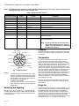
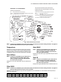
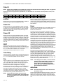
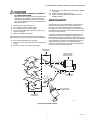
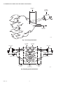
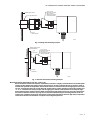
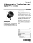
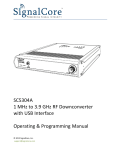
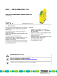
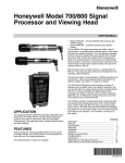
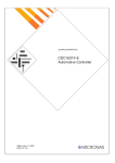
U2 Combination Viewing Head and Signal Processors USER MANUAL APPLICATION Each sensor in the U2 has a different response which is suitable for certain applications. The UVTRON tube detector has a peak response at 210 nm and is primarily for gas flame monitoring. This UV detector using pulse technology is the best for low NOx gas burners and where a solid state sensor, using flicker technology, does not provide satisfactory results. The solid state UV photodiode has a peak response at 310 nm. This sensor is suitable for gas, oil and coal. The principle of flame monitoring is flicker frequency based. User selectable high pass filters are used to reject signals that are from background radiation. INTRODUCTION The Honeywell U2 flame monitoring system combines sensing and processing in one package. The U2 is available in several models to provide different options. Each model includes one, two or three sensors which share the same optical axis. The U2 can be connected either through a detachable connector or a pipe fitting for installations with conduit. Refer to the table below for model numbers and options. The solid state IR photodiode has a peak response at 1400 nm. This sensor is suitable for low NOx oil and coal burners, low excess air oil burners, and burners with a limited view from a windbox front plate. The principle of flame monitoring is flicker frequency based. User selectable high pass filters are used to reject signals that are from background radiation. Contents Introduction ....................................................................... Application ........................................................................ Specifications ................................................................... Approvals .......................................................................... Installation ........................................................................ Accessories ...................................................................... Operation .......................................................................... Troubleshooting ................................................................ Communicating Through Modbus .................................... Manual Setup ................................................................... Automatic Setup ............................................................... Maintenance ..................................................................... Safety Manual ................................................................... Safety Function of the Uniscan 2 ......................... Proof Test Procedure ........................................... Proof Test Interval ................................................ Product Decommissioning ................................... 1 1 2 3 3 5 6 9 9 13 14 15 22 23 23 23 24 66-2071-02 U2 COMBINATION VIEWING HEAD AND SIGNAL PROCESSORS Table 1. Available models and associated features. Model Connector Connection U2-1010 Pipe Fit Connection (3/4 in. NPT) SSUV Sensor IR Sensor X X X U2-1010-PF X X X X U2-1010-PF-050* X X X X U2-1010-PF-100* X X X X U2-1012 X UVTron Sensor X U2-1012-PF U2-1016 X X U2-1016-PF U2-1018 X X X X X X U2-1018-PF X X X X X * The U2-1010-PF-050 has a 50-ft (15m) pigtail and the U2-1010-PF-100 has a 100-ft (30m) pigtail. 3. All models include the following: 1. Electronic check (no mechanical shutter) for self-check of the system. 2. 24 VDC input 4. 5. 6. Ten (10) flicker frequency filters for solid state UV and IR sensor (model dependent) Gain selection Eight (8) different file configurations Resettable fuses SPECIFICATIONS Power: 22-26 VDC, 120 mA max Paint: Silicone-free powder coat Output relay contacts SPST: 2 A, 30 VDC or 250 VAC Mounting/Process Connection: 1” NPT female NOTE: Refer to for Fig. 9 and Fig. 10 mounting examples. Ambient temperature: -40 to 70 ºC (-40 to 158 ºF) Pipe Fit Conduit Connection (-PF): 3/4” NPT Enclosure: IP66 FFRT: 1-3 second nominal, 2-4 second maximum NOTE: Optional air cooling for housing is available for applications with higher ambient temperatures. Please contact your distributor or Honeywell for assistance. Time Delay On: 0-3 seconds Fuses: Automatically resettable Weight: 2.8 kg (6.1 lbs) NOTE: If one of the devices is triggered due to high power draw, disconnect power from the system for a minimum of 30 seconds then reconnect power. Physical Dimensions: Diameter: 11.7 cm (4.6 inches) Length: 15.5 cm (6.1 inches) 66-2071—02 2 U2 COMBINATION VIEWING HEAD AND SIGNAL PROCESSORS APPROVALS The U2 is a FM approved combustion safeguard and flame sensing system. The U2 also carries the following approvals. Table 2. Approvals. Market FM-U.S. Pipe fit series (-PF) Connector series CLASS I, II, III DIV 1 GROUPS A, B, C, D, E, F, & G, T6 *Not for use in acidic or aliphatic hydrocarbon atmospheres. **Must be sealed at the enclosure. XP / I / 1 / ABCD / T6 Ta = -40°C to +70°C; DIP / II, III / 1 / EFG / T6 Ta = -40°C to +70°C; I / 1/ AEx d IIC / T6 Ta = -40°C to +70°C; 21/ AEx tb IIIC / T85°C Ta = -40°C to +70°C; CLASS I, II, III DIV 2 GROUPS A, B, C, D, E, F, & G, T5 DIP / II, III / 2 / EFG / T5 Ta = -40°C to +70°C; NI / I, / 2 / ABCD / T5 Ta = -40°C to +70°C; I / 2 / AEx nA nC IIC / T5 Ta = -40°C to 70°C; IP66 21/ AEx tb IIIC / T85°C Ta = -40°C to +70°C; FM-Canada XP / I / 1 / ABCD / T6 Ta = -40°C to +70°C; DIP / II, III / 1 / EFG / T6 Ta = -40°C to +70°C; I / 1/ Ex d IIC / T6 Ta = -40°C to +70°C; DIP / II, III / 2 / EFG / T5 TA = -40°C TO +70°C; NE / I, / 2 / ABCD / T5 TA = -40°C TO +70°C; I / 2 / EX NA NC IIC / T5 TA = -40°C TO 70°C; IP66 IEC IECEx FMG 13.0023X IECEx FMG 13.0023X Ex d IIC T6 Gb IP66 Ex tb IIIC T85C Temperature range: -40 to +185 ºF (-40 to +70 ºC) Ex nA nC IIC T5 Gc IP66 Ex tb IIIC T85C Temperature range: -40 to +185 ºF (-40 to +70 ºC) Special conditions of use for IECEx as indicated below. NOTES: Special Conditions for Safe Use: 1. Consult the manufacturer if dimensional information on the flameproof joints is necessary. 2. The aluminum surface of the Honeywell U2 flame monitoring system may store electrostatic charge and become a source of ignition in applications with a low relative humidity (<30 %) where the aluminum surface is relatively free of surface contamination such as dirt, dust or oil. Cleaning of the painted surface should only be done with a damp cloth. 3. The apparatus has flying lead conductors that exit the enclosure. A suitably certified Ex d or Ex e terminal box is required to be connected to apparatus enclosure for completing to external supply circuits. WARNING “Lockout” requires operator action. To prevent explosion in hazardous atmospheres, do not open housing. * Not including aliphatic hydrocarbons (hexane) and acids atmospheres in Class I, Division 1 locations. ** To reduce the risk of ignition of hazardous atmospheres, an approved sealing fitting is required at the enclosure in Class I, Division 1 locations. INSTALLATION Grounding and Shielding 4. IMPORTANT 5. Installer must be a trained, experienced flame safeguard service technician and should be familiar with the equipment operation and limitations and be aware of any applicable local codes and regulations. 1. 2. 3. Connect a safety ground to the U2 housing (if applicable). The U2 and all associated cable/conduit must be at least 12 inches (31 cm) from any source of high energy or voltage (for example, igniter equipment). Install a ground wire from the ignition transformer case to the igniter assembly. Ensure all igniter wires and cables show no signs of wear. Replace any igniter cables or wires that are frayed or cracked. The U2 must be electrically isolated from the burner front. a. Electrical isolation can be accomplished by installing an Ultem locking coupler adapter (R-518-PT12 or R-518-PT12L) in conjunction with a locking coupler (R-518-CL12-HTG or R-518-CL12-PG) between the viewing head flange and the burner mount. b. The purge air line should also be isolated from the viewing head. This can be accomplished by installing any insulating material, for example a rubber hose, in between the purge air line and the U2. Wiring U2 models with a pipe fitting have slightly different wiring than models with a removable connector. Refer to the table and diagram below for wire function, connection, and comments. Honeywell C12S cable colors are referenced for the Connector (CAB22) wires. 3 66-2071—02 U2 COMBINATION VIEWING HEAD AND SIGNAL PROCESSORS NOTE: If the fault and flame contacts are wired to 220 VAC voltage and cable runs are long, it may be necessary to use isolating/interposing relays to reduce induced noise. Table 3. U2 Wires and their function. Pipe Fitting Connection (CAB19) Connector (CAB22) Function Comments Drain wire Shield Cable shielding Tie to ground (black) Black Yellow/Green Ground Power ground Red Black #10 Power Connect to 22-26 VDC Green Yellow #3 Relay common Common for both flame and self check relays Yellow Yellow #4 Self check relay Normally open contact Grey Yellow #2 Flame relay Normally open contact Brown Yellow - RS 485 communication Modbus Connection White White + RS 485 communication Modbus Connection Blue Black #7 Future use Future use Orange Black #8 Current output 0-20 or 4-20 mA output corresponding to flame count. Use ground as return line. Purple Black #9 File select Grounded = parameter file 0 +24V = parameter file 1 NOTE: The file input wire should not be left unconnected or in an unknown state. If not being used or if using the default file 0, connect the file input wire to ground. Pressure NOT USED The U2 lens will withstand 500 psi. If the U2 will be exposed to pressures over 500 psi, contact your distributor or Honeywell for guidance. YELLOW WHITE YELLOW 2 BLACK 10 BLACK 9 Temperature YELLOW 3 BLACK 8 The U2 can withstand an ambient temperature of 158 ºF (70 ºC). The case temperature of the housing must not exceed 158 ºF (70 ºC). Purge air will help reduce conducted heat through the sight pipe and flange. A heat insulating Ultem locking coupler adapter (R-518-PT12, R-518-PT12L) is required and will reduce the conducted heat, however, direct radiation can cause the housing case temperature to exceed limits. If the ambient heat (direct radiation) is excessive, then a fiber optic extension should be considered. The extension uses a fiber optic cable assembly between the sight pipe and the U2, allowing the U2 to be placed further away from the heat source. Refer to the Fiber Optic Manual 69-2683 or contact your distributor or Honeywell for assistance with fiber optic selection and pricing. YELLOW 4 BLACK 7 YELLOW/GREEN SHIELD M33313 Fig. 1. Connector Pinout. NOTES: — — — It is recommended to use shielded pairs of cable. However, any cable can be used as long as analog output and communication cables are individually shielded. Honeywell offers C12S cable with 12 conductors for use with the U2. 18 AWG is recommended Wiring must be in conduit or tray as permitted by code. Hazardous location wiring must meet area classifications. The U2 models also have an internal sensor for measuring temperature. To access the temperature reading at the U2, refer to Fig. 2. Purge Air Mounting and Sighting The U2 does not have a purge air connection directly on it, so purge air must be provided via the mounting method. Refer to the ACCESSORIES section and Fig. 7 for suggested U2 mounting. Purge air is used to prevent very hot gases from reaching the U2 by continuously blowing cooler air through the sight pipe. Air required is about 0.13 Nm3/min (5 SCFM) delivered at 25 mm (1 in.) above the maximum back pressure as measured at the “Y” or “T” section of the purge air Mounting is 1 in. NPT (F). Refer to Fig. 7 for suggested U2 mounting. Before beginning the actual installation, determine the best location for mounting the viewing head based upon the following factors: 66-2071—02 4 U2 COMBINATION VIEWING HEAD AND SIGNAL PROCESSORS located during the aiming or sighting process. The “root” or intense spot may be further out than with the standard gas burner so it is imperative that a swivel mount be used when making sighting adjustments. connection. Use a flexible air supply line, to allow for repositioning of the U2 and sight pipe until a final and permanent position has been decided. A continuous flow of air must be maintained in order to reduce conducted heat and to keep the sight pipe and U2 lens free of dirt and debris. The air supply must be clean, free of oils and water, and preferably cool. In order to electrically isolate the U2, the purge air line should be installed using an insulating material, such as a rubber hose, in between the purge air line and the U2. As an example of proper sighting challenges, detecting flame in a sulfur recovery unit can present a challenge for IR flame monitors. The IR detector will detect natural gas used for the warm-up of the reactor. Usually the combustion air is turbulent enough to cause a good flicker signal. Clearance When sour gas is introduced and the natural gas is shut down, the flame signal could potentially drop off or drop out entirely due to a complete change in the flicker content for the existing U2 sighting. In this case, optimizing the flame signal for the sour gas by “zeroing-in” on this flame, and not the warm-up burner, may be beneficial. Make sure there will be sufficient room to remove the U2 for servicing. Mounting Honeywell offers a range of swivel mounts, both pipe thread or flange mounting for use with sight pipes or direct windbox mounting. Refer to the section “Accessories” on page 5. Once optimizing the sighting for the sour gas has been completed, the signal level could potentially be too low on the natural gas. In this case, using the UV detector for this application may be beneficial. It may be beneficial to use two sets of set points for Flame On and Flame Off, one set for proving and detecting the natural gas flame and the other for proving and detecting the sour gas flame. The switch-over from the two different files should be done when removing the natural gas burner. This can be implemented from the burner management system. The switch-over and the use of different files with independent settings is explained in the sections “File” on page 8 and “Manual Setup” on page 13. Viewing Head Sighting The sighting of the U2 should be parallel to the center line of the burner in the direction of the flame. If used, the sight pipe should be mounted as close to the center line as possible so as to sight along the flame rather than across the flame. Doing so will ensure continuing flame detection under changing load conditions. Refer to Fig. 4, 5 and 6. Utilizing a sighting or the sight pipe aimed at the root of the flame (where the turbulent combustion air mixes with the flame) is a good starting point for optimizing the sighting. Where practical, using a swivel mount to “zero-in” on the highest signal will assure the maximum performance. The optimum scanner location is parallel to the burner center line. The use of a swivel mount allows for line of sight adjustment, where practical to use. Another factor that needs to be considered when aiming the viewing head is the load condition of the boiler. The flames from a burner can be radically different at different loads. This is one of the reasons for choosing an optimum sighting initially that will maximize signal swing due to changing loads. ACCESSORIES Examples of U2 installation with and without a swivel mount are shown in Fig. 9 and Fig. 10. If using a sight pipe, the diameter should be large enough to allow a reasonable field of view and to allow for adjustment of the swivel mount angle. The following accessories are available for use with the U2. Orifice Disks (kit M-702-6) – Used to reduce the signal brightness in cases where the signal brightness is too strong. Located immediately in front of the lens, it will reduce the amount of signal to the sensors. Bag assembly contains orifice disks and retaining rings. Orifice disks come with 3/8, 1/4, 3/16 and 1/8 inch diameter holes. Contact your distributor or Honeywell for guidance in using orifice disks. Pulverized coal, unburned fuel, smoke, oil mist, dirt, dust and other impurities in the fuel can act as masking agents that attenuate the ultraviolet radiation that the flame emits. As well, sour gas (H2S) can readily absorb 200nm UV wavelengths, reducing the amount of ultraviolet radiation reaching the detector. Care should be taken to select the proper viewing head for the fuel used. Additionally, the contaminants that mask UV can be diluted by providing a strong flow of air through the sight pipe to clear a viewing path through the attenuating material. Refer to the Purge Air section of this manual. Locking coupler with purge port (R-518-CL12-PG) – Adapter is a 1 in. NPTM locking quick disconnect/cam and groove coupler with 1/2 in. NPT purge port. Used with R-518PT12 and R-518-PT12L insulating locking coupler adapters. Insulating locking coupler adapters (R-518-PT12 and R518-PT12L) – 1 in. NPTM Ultem adapters insulate the viewing head from heat and are used with the R-518-CL12-PG purge air adapter or the R-518-CL12-HTG locking coupler. The R518-PT12L has a quartz lens. It may also be desirable to sight the detector at an area containing fewer masking agents such as near the burner nozzle or near the entrance of the combustion air. Increasing the viewing area of the detector by shortening the sight pipe or by increasing the diameter of the sight pipe can also reduce the attenuating effect of masking agents. Swivel mounts (M-701-1, M-701-2, M-701-2-FLG, M-701-2SS, M-701-3, M-701-3P, M-701-4) – All have 1 in. NPTF viewing head connections on one end with varying process connections including 2 in. pipe slip-on, 2 in. NPTF, 2 in. flanged, 2 in. NPT in stainless steel construction, 4.5 in. flanged with 3 bolts, 3 in. NPTF and 2-bolt flanged. With low NOx gas burners, the UV radiation is usually much less in intensity and spread out. Relatively high readings can be obtained from all over the furnace when many burners are on. This is particularly true when flue gas recirculation is used. There will however, be a relatively stronger signal near the “root” of the flame and the more intense spot should be 5 66-2071—02 U2 COMBINATION VIEWING HEAD AND SIGNAL PROCESSORS Locking coupler (R-518-CL12-HTG) – Used with the R-518PT12 and R-518-PT12L insulating locking coupler adapters. Process connection end is 1 in. NPTF. To further assist in flame discrimination setup, adjustable “Flame On” and adjustable “Flame Off” thresholds are also provided. The Flame On threshold and Flame Off threshold can then be set to monitor the target burner flame but to reject background radiation from other burners. Connector (R-518-10) – Quick disconnect connector for all non-pipe fitting U2 models. In order to energize the flame relay, the flame count must be higher than the programmed “Flame On” threshold for greater than the “Time Delay” value. Once the flame relay is energized, the flame signal can fall below the programmed Flame On threshold setting. As long as the flame signal remains above the programmed “Flame Off” setting, the system will continue to operate. When the flame signal falls below the programmed “Flame Off” threshold, it will not be deenergized until after the “FFRT” (flame failure response time) expires, unless “Flame On” is detected. NOTE: Connector is not included with the non-pipe fitting models. Order separately along with cable and required mounting accessories. Cable (C12S) – 12 conductor cable with braided shield. Sold per foot. NOTE: Cable is not included with the non-pipe fitting models. Order separately along with connector and required mounting accessories. The U2 includes a self check relay which should always be energized whenever the U2 has power. The self check relay is de-energized (failsafe) when an internal fault is detected. The self check relay is factory wired in series with the flame relay. One additional contact is provided for alarm purposes. Cable+ Connector (ASY964) – Pre-assembled 15-foot (4.7m), 12-conductor cable (C12S) with quick disconnect (R518-10) for all U2 non-pipe fitting models. Fiber Optic System Compatibility – The U2 models are compatible with the Honeywell FASA fiber optic extension products. The S550FOAD, S550FOADY-FT and S550FOADYFT-AL adapters are applicable. Contact your distributor or Honeywell for assistance with fiber optic selection and pricing. Self-Checking There is a small processor in all viewing heads and it is possible that it could fail and produce erroneous viewing head pulses. The self-check circuitry guards against such an occurrence. There are several tasks that require intelligent interaction between the viewing heads and the signal processor. If all of the interactions do not occur properly, the flame relay will open. USB to RS422/RS485 Converter (COMMOD) – Protocol converter for use with external communication to a remote computer. OPERATION User Interface IR and UV Detectors A touch wheel located on the back of the U2 is used for operator interface. The configuration menu is simple and easy to follow. Full character 4 digital scrolling LED displays are visible in the dark or sunlight. Individual sensor LEDs (3 total located below the display) flash to indicate the output of each sensor (green = UVT, Blue = SSUV, Red = IR). The upper right green self-check LED provides status of the hardware while the upper left red “Flame On” LED provides status of the flame relay (main safety device). See Table 1 on page 2 to determine which sensors are active in your U2 model. The UVTron tube sensor responds to UV radiation from different fuel flames. The UVTron sensor generates pulses that are electronically conditioned to provide output indicated on the U2 display from 0000 to 3425 units. The signals from the UVSS solid state sensor are processed based on flicker principle using FFT (Fast Fourier Transform). User selectable high pass filters are used to reject signals that are from background radiation. NOTE: The number of LEDs is model dependent. The touch wheel is designed like an iPod™ to allow for slow or fast changes by moving a finger slower or faster around the back glass. Alternatively the user may tap (-) or (+) to make changes. Tap ENTER/STORE to enter a menu or store selected data. Tap BACK to return to the previous menu. Exiting all the menus will display the current flame count. The U2 menus are detailed below. The signals from the IR solid state sensor are processed based on flicker principle using FFT (Fast Fourier Transform). User selectable high pass filters are used to reject signals that are from background radiation. Each sensor allows independent adjustment for gain. For flicker-based sensors, there is also a high pass filter setpoint. 66-2071—02 6 U2 COMBINATION VIEWING HEAD AND SIGNAL PROCESSORS HONEYWELL U2 PROGRAMMING TWO BUTTON INTERFACE (BACK AND ENTER) EVERYTHING ELSE CAN BE DONE BY SCROLLING INTERFACE TECHNIQUES: INTERFACE MODES: TAP: PRESS FINGER ON BUTTON AND REMOVE. SCROLL: PRESS FINGER ON GLASS AND MOVE FINGER IN CIRCLES (TWIRL). RAMP: HOLD FINGER ON THE + OR - BUTTON. FLAME DISPLAY: TAP BACK (MAY REQUIRE MORE THAN ONE TAP). HELP: TAP + OR - (FROM DISPLAY). LAST MENU: TAP ENTER, MOVE THROUGH MENU WITH TAPS OR SCROLLS. ADJUST MODE: TAP ENTER FROM ADJUSTABLE MENU ITEM, CHANGE VALUE USING ANY TECHNIQUE. NO YES MODE: CHANGE TO YES AND TAP STORE. 4 SUB MENUS FACTORY DEFAULT VERSION HOURS FILE DEFAULT ON OFF °F OR °C READ ONLY WRITE ONLY RS485 DEFAULT 0->20 OR 4->20 IRDA PARITY 127 °F AUTO FILTER GAIN TUBE UV - AUTO GAIN ADDRESS- 3425 GT32 GAIN SS UV- G 32 COMMS NONE ODD EVEN BAUD 2400 9600 38400 115200 BACK A000 PANEL 4800 19200 57600 HELP FILE *F01 TD03 GAIN IR- ENTER STORE TIME DELAY- FILTER IR- LAST MENU FFRT0000 PANEL LOCK RT01 GAIN MA OUT- FLAME OFF- 0000 TIME OUT MIN F 09 FILTER SS UV- HELP GI32 FI04 GM32 FLAME ON- 0600 0800 M33314 Fig. 2. User interface menu overview. NOTE: If sensor is not available in your model, then no menu item will exist for sensor setting. See Table 1 on page 2 to determine which sensors are active in your U2 model. Temperature Gain SSUV Displays the processor temperature. Tapping enter will bring the user into the submenu which will allow changes between displaying Celsius or Fahrenheit, display the software version, or display the number of hours the unit has been in operation. NOTE: If sensor is not available in your model, then no menu item will exist for sensor setting. See Table 1 on page 2 to determine which sensors are active in your U2 model. Gain UVTron Displays the solid state UV gain (adjustable 0-99) The default value is 75. NOTE: If sensor is not available in your model, then no menu item will exist for sensor setting. See Table 1 on page 2 to determine which sensors are active in your U2 model. Gain IR NOTE: If sensor is not available in your model, then no menu item will exist for sensor setting. See Table 1 on page 2 to determine which sensors are active in your U2 model. Displays the Uvtron gain (adjustable 0-99). The default value is 32. Displays the IR gain (adjustable 0-99). The default value is 75. Filter SSUV NOTE: If sensor is not available in your model, then no menu item will exist for sensor setting. See Table 1 on page 2 to determine which sensors are active in your U2 model. Displays the current solid state UV high pass filter (adjustable 0-9). The default filter is 3. See the filter cutoff frequencies (in Hertz) in the table below. FILTER 0 1 2 3 4 5 6 7 8 9 HERTZ 9 16 24 33 52 75 100 155 215 300 7 66-2071—02 U2 COMBINATION VIEWING HEAD AND SIGNAL PROCESSORS Filter IR NOTE: If sensor is not available in your model, then no menu item will exist for sensor setting. See Table 1 on page 2 to determine which sensors are active in your U2 model. Displays the current IR high pass filter (adjustable 0-9). The default filter is 3. See the filter cutoff frequencies (in Hertz) in the table below. FILTER 0 1 2 3 4 5 6 7 8 9 HERTZ 9 16 24 33 52 75 100 155 215 300 mA Out When connected to 24 Vdc, the file selection = “1”. The other means of selecting and activating a file is via the Modbus RTU interface using register address 40093. Modbus interface can be accomplished via FlameTools software or another Modbus RTU interface. Displays the current output gain (adjustable 0-99) or “OPEN” if the current output is open. The default value is 32. Flame On Panel Displays the flame on value (adjustable 51-3425). The flame on value can not be adjusted below the flame off value. When the flame count is greater than the flame on value for greater than the time delay value, the flame relay will energize. The default value level is 800. Tapping the ENTER/STORE button when PANEL appears on the menu screen will provide access to two sub-menus; Panel Lock and Time Out. The Panel Lock sub-menu enables or disables a security feature that locks the U2 interface, preventing any parameter modifications. To enable this feature, a special 4-digit access code is required, which is available from the factory. It requires that same code to unlock, allowing parameter changes after it has been enabled. Once the Panel Lock feature is enabled by entering the code, the panel is locked out immediately from further adjustment. If a user attempts to modify any U2 parameters while the Panel Lock feature is enabled, a lockout message will appear on the display. The display will show “Bad” upon entry of an incorrect access code. If the password is forgotten or lost, the user must contact the factory for assistance with unlocking the panel. At that point, the user can reset or deactivate the password. Once the appropriate code is entered and the Panel Lock sub-menu accessed, it is automatically disabled. The default setting for the Panel Lock feature is disabled/OFF. Flame Off Displays the flame off value (adjustable 50-3424). The flame off value can not be adjusted above the flame on value. When the flame count is less than the flame off value for greater than the FFRT value, the flame relay will de-energize. The default value level is 600. Flame off is usually set to approximately 2/3 the value of flame on, however this value should never be less than 100. FFRT The flame failure response time is the time it takes for the flame relay to de-energize after the flame count falls below the flame off value. FFRT (flame failure response time) can be set to 1, 2, or 3 which will not exceed 2, 3, or 4 seconds respectively. The factory default value is 1 second. The Time Out sub-menu allows the user to enter a time allotment from 0-9999 minutes in which to allow adjustments of settings before the panel returns to monitoring mode and the touch wheel disables itself if there is no menu activity. Panel Time Out helps prevent accidental changes to parameter settings. Once the panel has timed out, to modify settings, simply enter “1234” as prompted by the display. The Panel Time Out is by default 9999 minutes. Time Delay The time it takes for the flame relay to energize after the flame count rises above the flame on value. Time delay can be set to 0, 1, 2, or 3. The factory default value is 3 seconds. File NOTE: If the display shows “9999”, it can also indicate saturation of the UVSS and/or IR sensor. If the problem persists after checking the panel lockout feature and resetting as described above, refer to the Troubleshooting section of this document for instruction. The U2 is able to store up to 8 different file configurations (file0 – file7). Settings that are stored include: UVT gain, SSUV gain, IR gain, SSUV filter, IR filter, mA output, gain, flame on, flame off. File 0 is default. NOTE: The U2 touch wheel interface allows access to all eight files for changing parameters, however, the file selection cannot be changed via the U2 interface; it can only be changed via the “File Select” wire input or modbus. Only two files, “0” and “1” may be automatically activated by changing the voltage input to the “File Select” wire (purple or black #9). Refer to Table 3. When the file select line is grounded, the file selection = “0”. Auto Gain NOTE: Auto Gain and Auto Filter cannot be used with U2-1016-PF model. Routine that automatically determines the gain for the IR and SSUV sensors (that are on) necessary to generate a total flame count of approximately 1200. Be sure that all desired sensors are turned on (gain of at least 1) before the routine is run. NOTE: The file input wire should not be left unconnected or in an unknown state. If not being used or if using the default file 0, connect the file input wire to ground. 66-2071—02 8 U2 COMBINATION VIEWING HEAD AND SIGNAL PROCESSORS Auto Filter “Bad” Message Routine that automatically determines the optimum filter for the SSUV and IR sensors. This routine should only be done after the AUTO GAIN routine. If the display shows “Bad” upon entering the access code for the PANEL Lock feature, it means the access code that was just entered is incorrect. Refer to the Panel section of this manual for further details. NOTE: While using the Auto Gain and Auto Filter modes, the system will be adjusting to the firing conditions at the time of implementation. This condition should be carefully selected to ensure discrimination through complete load changes from minimum to maximum and from cold burner/boiler startup to hot burner/boiler startup. NOTE: Refer to “Grounding and Shielding” on page 3 for further troubleshooting help in regards to proper grounding and shielding techniques. COMMUNICATING THROUGH MODBUS Default Modbus RTU communication protocol allows the U2 to communicate with any process controllers or human-Interface host computers that support this protocol. When communicating through Modbus, use the following register map to access and control the U2: Tapping will access the file default and factory default sub menus. File Default Changes the settings of the current file being adjusted (see FILE menu). — — — — Factory Default Changes all settings to factory default settings. Communications, security, and all file settings will have to be reset so only initiate factory defaults when absolutely necessary. 9600 baud (default) 8 data bits no parity (default) 1 stop bit Baud, parity, and address are all changeable via the U2 interface in the “Comms” menu. The address is set to 0 by default and must be changed in order to communicate with the unit. When communicating with more than one unit ensure that no two units share the same address. TROUBLESHOOTING A graphical user interface is available for remote configuration and monitoring through Modbus called Flame Tools. Refer to Table 4 and 5 for the Modbus registers map. “9999” on Display “9999” on the U2 display can indicate saturation of the UVSS and/or IR sensor in addition to the PANEL Time Out sub-menu being accessed. First check to see if the PANEL Time Out sub-menu has been accessed and exit the menu as described in the Panel section of this document. If the problem still persists, then sensor saturation is likely. Decrease the gain for UVSS and/or IR sensor to 0, then gradually increase the gain level(s) to a suitable level to prevent saturation. In rare cases, an orifice disk may be required. Refer to the ACCESSORIES section of this document for part numbers. Comms Tapping COMMS on the U2 menu will access the communications sub menus including address, baud, parity, IRDA, RS485, and current output. Address Address for modbus communication (0-247). When communicating with more than one unit ensure that no two units share the same address. The default address is 0 so it must be changed before modbus communication can take place. For applications where large quantities of U2 are used, it is recommended to start with address 11 for burner #1, 21 for burner #2 and so on. Refer to Fig. 3. Doing so will help alleviate potential communication issues when adding new or replacing existing U2 models, which have zero (0) as the default address. Two units with a 0 address could seize communications. If saturation of the IR or SSUV sensor persists for greater than 1 second, the flame Relay will open, and the U2 will lock out with an error code: code 1 for SSUV saturation and code 8 for IR saturation. When a lockout occurs, the U2 must be reset to continue normal operation. This is accomplished by pressing the enter key twice at the front panel. Lockout Message If a lockout message appears on the screen, the user has attempted to access the U2 menus while the PANEL Lock feature is enabled. The Lock feature requires a special 4-digit code for access and modification, which is available from the factory. If the password is forgotten or lost, the user must contact the factory for assistance with unlocking the panel. Refer to the Panel section of this manual and/or contact the factory for assistance. Baud Speed of modbus communications (2400, 4800, 9600, 19200, 38400, 57600, or 115200). The default baud is 9600. Parity Modbus checking method (NONE, ODD, or EVEN). The default parity is NONE. 9 66-2071—02 U2 COMBINATION VIEWING HEAD AND SIGNAL PROCESSORS IRDA 0 OR 4-20 Enables or disables communications through the palm. Enabled by default. Sets the current output to either a 0-20mA output or a 4-20mA output scale. The 4-20mA output scale is used by default. RS485 Sets modbus to either READ ONLY or read and writable (WRITE OK). Read and writable by default. Table 4. Basic MODBUS Registers Map. Register Name Description Minimum Maximum Size 40001 FLAMECOUNT Flame count of active channel (read only) 40002 PROCSTATUS Bit mask: only 4th bit (4 of 20) is writable, other bits are read 0 only Not used (0000 0001) don’t care Relay (0000 0010) 1=on, 0=off Not lockout (0000 0100) 1=not lockout, 0=lockout Not panel lock (0000 1000) 1=unlocked, 0=locked 4 to 20 (output) (0001 0000) 1 (default)=4-20mA, 0=020mA File (1110 0000) 3 bits are the file in use (0-7) 40003 FLAMEON Flame On setting for current active file 51 3425 16 bit 40005 FLAMEOFF Flame Off setting for current active file 50 3424 16 bit 40007 OUTPUTGAIN Gain of the0/4-20mA output for the current active file 0 99 8 bit 40010 IRGAIN IR sensor gain setting for current active file 0 99 8 bit 40011 IRFILT High pass IR sensor filter setting for current active file. 0=8Hz 0 (default), 1=16Hz, 2=24Hz, 3=33Hz, 4=52Hz, 5=75Hz, 6=100Hz, 7=155Hz, 8=215Hz, 9=300Hz 9 8 bit 40012 UVTGAIN UV tube gain setting for current active file 99 8 bit 40015 UVSSFILT High pass solid state UV sensor filter setting for current active 0 file. File 0=8Hz (default), 1=16Hz, 2=24Hz, 3=33Hz, 4=52Hz, 5=75Hz, 6=100Hz, 7=155Hz, 8=215Hz, 9=300Hz 9 8 bit 40016 UVSSGAIN Solid state UV sensor gain setting for current active file 0 99 8 bit 40019 TEMPERATURE Current internal temperature of U2 (read only) -67 261 16 bit 40021 TIMEDELAY Time Delay setting (in seconds) for current active file 0 3 8 bit 40022 FFRT FFRT (flame failure response time) setting (in seconds) for current active file 1 3 8 bit 40023 VERSION Firmware version (read only) -32768 32767 16 bit 40085 BAUD Baud rate setting (bits/second). Only affects RS-485 communication, not IRDA. Default is 9600. The U2 and the master device must have the same baud settings. 24 1152 16 bit 40086 PARITY Parity setting. Only affects RS-485 communication, not IRDA. 0 0-no parity (default), 1=odd parity, 2=even parity 2 8 bit 40087 ADDRESS Modbus address of U2 used by RS-485 and IRDA. Each flame 0 monitor must have a unique address. 247 8 bit 40092 NUMFILES User set limit on the number of files able to be used. Default=8. 1 8 8 bit 40093 FILE Current active file number. Default=0. 7 8 bit 40095 TUBEFLAME Flame count from the UV tube sensor only (read only) -32768 32767 16 bit 40096 IRFLAME Flame count from the IR sensor only (read only) -32768 32767 16 bit 40097 SSUVFLAME Flame count from the solid state UV sensor only (read only) -32768 32767 16 bit 66-2071—02 10 0 0 0 3425 16 bit 255 8 bit U2 COMBINATION VIEWING HEAD AND SIGNAL PROCESSORS BOILER 1 ADDRESS BNR 1 11 BNR 2 12 BNR 3 13 BNR 4 14 ADDRESS BNR 1 31 BNR 2 32 BNR 3 33 BNR 4 34 BNR 5 15 BNR 6 16 BOILER 3 MODBUS MASTER CONTROL FOR PF VERSION CAB 19: + = WHITE – = BROWN FOR QD VERSION CAB 22: + = WHITE – = YELLOW NOTES: – A CONVERTER MAY BE NECESSARY FOR COMMUNICATION WITH THE MODBUS MASTER CONTROL. – USE SHIELDED CABLE FOR COMMUNICATION WIRING. M33521 A TDA(–) B TDB(+) C RDA(–) D RDB(+) E GND NOTES: GND RDA(–) RDB(+) TDA(–) PRODUCT SIDE TDB(+) Fig. 3. Typical Communication Wiring and Recommended Addressing. WIRE SIDE COMMOD USB TO RS422/485 CONVERTER CONVERTER CONNECTOR DESCRIPTION U2 CONNECTOR (CAB22) U2 PIPE FITTING (CAB19) TDA (-) DATA A (-) INPUT/OUTPUT YELLOW BROWN TDB (+) DATA B (+) INPUT/OUTPUT WHITE WHITE RDA (-) DATA A (-) INPUT/OUTPUT RDB (+) DATA B (+) INPUT/OUTPUT GND GROUND SHIELD DRAIN WIRE SELECT THE APPROPRIATE DIP SWITCH SETTINGS FOR RS-485 COMMUNICATION PER THE VENDOR’S INSTRUCTION SHEET. SOFTWARE DRIVERS MAY BE DOWNLOADED FROM B&B ELECTRONICS’ WEBSITE. M33862 Fig. 4. Wiring of RS422/485 to USB Converter to U2. 11 66-2071—02 U2 COMBINATION VIEWING HEAD AND SIGNAL PROCESSORS 1 (25) NPT CONNECTION 1(25) 5-3/32 (130) 4-19/32 (118) 2-29/32 (73) Fig. 5. U2 dimensions. 66-2071—02 12 3/4 (19) NPT CONNECTION M34431 U2 COMBINATION VIEWING HEAD AND SIGNAL PROCESSORS MANUAL SETUP NOTE: Above is a simplified version of discrimination adjustments. Manual Configuration for Gas Firing Applications with Multiple Burners Vessels equipped with a large number of burners, “T” fired units and cross fired boilers will require several adjustments including use of multiple files for obtaining the required discrimination. CAUTION ALL ADJUSTMENTS SHOULD BE CARRIED OUT Manual Configuration for Oil Firing Applications with Multiple Burners BY A QUALIFIED PERSON. BMS interlock(s) may require temporary bypass during configuration. This operation should be carried out under supervised conditions and limited to minimum time. Remove bypasses as soon as configuration and setup is completed. CAUTION ALL ADJUSTMENTS SHOULD BE CARRIED OUT BY A QUALIFIED PERSON. BMS interlock(s) may require temporary bypass during configuration. This operation should be carried out under supervised conditions and limited to minimum time. Remove bypasses as soon as configuration and setup is completed. Main gas control valve may include bypass PRV. Make sure at least first burner is started up at minimum firing. In some cases more than one burner may be started up at low fire depending upon bypass PRV. Follow manufacturer’s guidelines in controlling fuel flow as additional burners are brought into service Main oil control valve may include bypass PRV. Make sure at least first burner is started up at minimum firing. In some cases more than one burner may be started up at low fire depending upon bypass PRV. 1. 2. 3. Go to menu for UVTron. Adjust gain settings to 50 If applicable, go to UVSS menu and set UVSS gain to zero. With zero gain, flicker frequency filter need not be adjusted. 4. If applicable, go to IR menu and set IR gain GI to zero. With zero gain, flicker frequency filter need not be adjusted. 5. Go to Milliamp output gain GM and set at 50 6. Go to Flame ON menu. Set this to 800 as an initial value. 7. Go to Flame OFF menu. Set Flame OFF 600 as an initial value. 8. Go to Flame Failure Response Time (FFRT). Select 3 seconds 9. Go to Time Delay and select “0” seconds. 10. Under supervised conditions, light off gas igniter. 11. The viewing head will show in Green (UV mode) reading between 0-3425. 12. If necessary and when mounted on swivel mount or adjustable device, adjust line of sight for the viewing head for maximum signal. Lock up viewing head in this position. 13. If selected setting is not correct to recognize igniter flame, adjust UV gain. 14. Start the main gas firing per manufacturer's instructions. 15. REPEAT THE ABOVE FOR ALL BURNERS - ONE AT A TIME. After all burners are in service and boiler load is above 90%, perform the following for discrimination tests and adjustments. Follow manufacturer’s guidelines in controlling fuel flow as additional burners are brought into service. For vessels equipped with gas igniters follow setup procedure described above. For best discrimination, two channels may be required to accommodate two different fuels firing. As an example, after the gas igniter is established, introduce oil to the burner and change the file number selection. 1. 2. 3. 4. 5. 6. 7. 8. 9. 10. 11. a. Turn off the burner b. Check if background signal is below “Flame Off” threshold. If not, increase Flame Off threshold so the background count is below set point c. After 1 minute, re-start burner on pilot and then main gas fuel. d. Check that the U2 recognizes the pilot and main flames. If the flame signal is below Flame On threshold, lower Flame On threshold below flame on signal. e. Repeat all tests if any changes are made to Gain, Flicker set point, Flame On and Flame Off Threshold. 12. 13. 14. 15. 13 Go to menu for IR sensor. Adjust gain settings to 50. Adjust Filter set point to 1 If applicable, go to UVSS menu and set UVSS gain to zero. With zero gain, flicker frequency filter need not be adjusted. Go to Milliamp output gain GM and set at 50 Go to Flame ON menu. Set this to 800 as an initial value. Go to Flame OFF menu. Set Flame OFF 600 as an initial value. Go to Flame Failure Response Time (FFRT). Select 3 seconds Go to Time delay and select “0” seconds. Under supervised conditions, light off oil igniter (if applicable). The viewing head will show in Red (IR mode) reading between 0-3425. Skip this step if the viewing head is already adjusted for gas igniter. If necessary and when mounted on swivel mount or adjustable device, adjust line of sight for the viewing head for maximum signal. Lock up viewing head in this position. If selected setting is not correct to recognize oil igniter flame, adjust IR gain and filter. Start the main oil firing per manufacturer's instructions. REPEAT THE ABOVE FOR ALL BURNERS - ONE AT A TIME. 66-2071—02 U2 COMBINATION VIEWING HEAD AND SIGNAL PROCESSORS For vessels equipped with gas igniters, follow setup procedure described above. For best discrimination, two to three files may be required to accommodate three different fuel firings. After all burners are in service and boiler load is above 90%, perform the following for discrimination tests and adjustments. a. Turn off the burner b. Check if background signal is below “Flame Off” threshold. If not, increase Flame Off threshold so the background count is below set point. If the background flame signals are too high, increase IR filter setting to a higher value starting with 2 3 4 5, until background count is below Flame Off threshold point. 1. 2. 3. 4. 5. 6. 7. 8. 9. 10. 11. NOTE: With IR sensor, two adjustments are available: gain and flicker set point. Both may require adjustment to obtain the required discrimination. In general, flicker filter adjustment works better for discrimination than gain adjustment. 12. c. After 1 minute, re-start burner on pilot and main oil burner. d. Check that U2 recognizes the pilot and main flames. If the flame signal is below Flame On threshold, lower Flame On threshold below flame on signal. e. Repeat all tests if any changes are made to Gain, Flicker set point, Flame On and Flame Off Threshold. 13. 14. 15. 16. NOTE: Above is simplified version of adjustment. Vessels equipped with a large number of burners, “T” fired units and cross fired boilers will require several adjustments including use of multiple files for obtaining the required discrimination. 17. 18. Manual Configuration for Coal Firing Applications with Multiple Burners 19. 20. 21. 22. 23. In general, coal firing units are equipped with several coal mills. Each coal mill may supply pulverized coal to several burners. 24. For units equipped with a gas igniter and gas warm-up burners, two dedicated files for each U2 are highly recommended. One file should be dedicated to the gas igniter and warm-up gas burners, and the other to main coal. 25. 26. For units equipped with a gas igniter and oil warm-up burners, two files are recommended; one file for the gas igniter and the other for the oil warm-up burners and main coal firing. NOTE: Above is simplified version of adjustment. Vessels equipped with a large number of burners, “T” fired units and cross fired boilers will require several adjustments including use of multiple files for obtaining the required discrimination. NOTE: Alternately, 3 files may be used, however, only two files may be selected via the “File Select” 0/ 24 Vdc input on the U2. The third file must be selected via a Modbus RTU interface. Refer to Table 3 and the “FILE” section of this document. AUTOMATIC SETUP NOTE: For single burner systems only. Multiple burners require several manual adjustments to obtain the proper discrimination. CAUTION ALL ADJUSTMENTS SHOULD BE CARRIED OUT BY A QUALIFIED PERSON. BMS interlock(s) may require temporary bypass during configuration. This operation should be carried out under supervised conditions and limited to minimum time. Remove bypasses as soon as configuration and setup is completed. 66-2071—02 Establish igniter flame as described above. Start warm-up oil burner. Go to IR menu and adjust gain setting to 50. If equipped with UVSS sensor adjust gain to 0 Adjust IR filter to 1 and UVSS filter to 9 Go to milliamp output gain and adjust to 50 Go to Flame ON and adjust to 1200 Go to Flame off and adjust to 800 Go To FFRT and adjust to 3 seconds Go to Time Delay and adjust to zero “0” seconds With oil firing at the minimum on the first burner - adjust gain up or down to be just above 1200 One by one light-off the remaining burners and adjust gain as necessary. When all mill burners are firing oil, start pulverizer system. Adjust mill output to minimum coal flow as recommend by the manufacturer. If the signal is still above Flame On for all burners associated with the mill, no further adjustment will be necessary. Repeat for at least one more mill by establishing gas igniters and oil burners for the mill. When first Mill is established, turn off the warm-up burners - one by one. If the signal falls below the Flame Off point, adjust gain to higher value so that signal remains above Flame Off point. After all oil burners and igniters are off, adjust mill coal flow as per manufacturer recommendations. Repeat for all mills. Go back to first mill - reduce coal flow to minimum. Establish igniter and oil burners. Stop the mill as per manufacturer's recommendations. Sweep the mill of coal and then shutdown oil burners; if igniters are in service, turn off igniters. If the flame signal from the back ground is above the Flame Off point - increase Flame Off set point and/or increase filter frequency set point. Make adjustment to all units associated with this mill. RE-ESTABLISH THE MIL AND REPEAT THE ABOVE FOR THE REMAINING MILLS - ONE AT A TIME. 14 U2 COMBINATION VIEWING HEAD AND SIGNAL PROCESSORS 9. CAUTION ALL ADJUSTMENTS SHOULD BE CARRIED OUT 10. 11. BY A QUALIFIED PERSON. BMS interlock(s) may require temporary bypass during configuration. This operation should be carried out under supervised conditions and limited to minimum time. Remove bypasses as soon as configuration and setup is completed. 1. 2. 3. 4. 5. MAINTENANCE The UV tube sensor has a limited lifespan. Under extreme conditions, the lifespan can be as low as 10,000 hours. However, in the most favorable conditions, the lifespan is 50,000 hours or more. The service life of the UV tube sensor is considered terminated when the sensitivity becomes lower then 50% of the initial value. Adjust all sensor gain settings to 50. Go to Flame ON menu. Set this to 800. Go to Flame OFF menu. Set this to 600. Go to the AUTO GAIN menu, tap enter, scroll to “yes” then tap enter again. Wait as instructed by the display. A monthly sensitivity check is suggested to determine if the UV tube sensor's life is terminated. The reading of the U2 digital display should be compared to the initial reading of the unit when it was installed. Ensure similar burner fire conditions of the application, and that the same gain settings are used during each sensitivity check. If it is determined that the sensitivity is below 50% of the initial value (terminated life of sensor), the sensor should be replaced. After the burner is in service and boiler load is above 90%, perform the following for discrimination tests and adjustments. 6. 7. 8. Ensure the current flame count is less than the FLAME OFF value. Restart the burner being monitored. Ensure the current flame count is greater than the FLAME ON value. Go to the AUTO FILTER menu, tap enter. Turn off the burner being monitored as instructed by the display. Tap enter, scroll to “yes” then tap enter again. HIGH FREQUENCY FLICKER ZONE DETECTOR IN GOOD SIGHTING POSITION (PARALLEL SIGHTING) BURNER NOZZLE CENTERLINE DETECTOR IN POOR SIGHTING POSITION LOW FREQUENCY FLICKER ZONE M33285 Fig. 6. IR viewing head location. 15 66-2071—02 U2 COMBINATION VIEWING HEAD AND SIGNAL PROCESSORS UV RADIATION ZONE UV VIEWING HEAD SIGHTED ON UV ZONE BURNER NOZZLE CENTERLINE M33286 Fig. 7. UV viewing head location. NO. 1 FLAME ENVELOPE NO. 2 FLAME ENVELOPE VIEWING HEAD VIEWING HEAD BURNER NOZZLE NO. 1 BURNER NOZZLE NO. 2 HIGH FREQUENCY IR ZONE LOW FREQUENCY ZONE (LESS THAN 36Hz) HIGH FREQUENCY IR ZONE Fig. 8. Sighting opposed fired burners. 66-2071—02 16 M33287 U2 COMBINATION VIEWING HEAD AND SIGNAL PROCESSORS BURNER FRONT PLATE 2 (51) NPT NIPPLE TOE R-518-CL12-PG PURGE AIR COUPLER AND R-518-PT12 INSULATING LOCKING COUPLER ADAPTER M-701-2 SWIVEL MOUNT M33524 Fig. 9. Viewing head mounting example. BURNER FRONT PLATE OR WINDOWBOX 1 (25) NPTF PIPE R-518-CL12-PG PURGE AIR COUPLER AND R-518-PT12 INSULATING LOCKING COUPLER ADAPTER FLANGE (OPTIONAL) M33628 Fig. 10. Second vertical head mounting example. Mounting Examples (applicable to both Fig. 7 and Fig. 8): Due to the heat and electrical insulation requirements of the U2, it is highly recommended to use the Honeywell locking coupler adapter and locking coupler accessories for mounting, attached directly to the U2. In order to maintain the specified U2 temperature, the minimum distance to mount the U2 from the sight pipe is 2.3 inches (5.8 cm), using the R-518-PT12/L and the R-518-CL12-HTG locking coupler. Cooling air should be provided via a “Y” or “T” in between the locking coupler and the sight pipe to reduce conducted heat and to keep the sight pipe and U2 lens clean of debris and dirt. Refer to the Mounting and Sighting section on purge air requirements. For electrical isolation reasons, the purge air line should be installed using an insulating material, such as a rubber hose, in between the purge air line and the viewing head. Note that an extension pipe may be required to locate the U2 further from the burner front plate to avoid high temperatures. 17 66-2071—02 U2 COMBINATION VIEWING HEAD AND SIGNAL PROCESSORS Table 5. Extended Modbus Register Map. Register Name Description Minimum Maximum Size 40017 SENSORS Bit mask: shows populated sensors (model dependent, read only) UV tube (0000 0001) 1=on, 0=off IR sensor (0000 0010) 1=on, 0=off SSUV (0000 0100) 1=on, 0=off Display (0000 1000) 1=on, 0=off Wheel (0001 0000) 1=on, 0=off 0 255 8 bit 40020 HIGHTEMP Stores the highest internal temperature (ºC only) the U2 has achieved (read only) 0 261 8 bit 40060 SERIALNUM Factory set identification number (read only) -32768 32767 16 bit 40061 IDNUM User set identification number -32768 32767 16 bit 40062 OP2HOURS Total run time in 2 hour increments (read only) -32768 32767 16 bit 40089 KEYTIMEOUT Time (in minutes) before the touch wheel will disable itself. 0 Default of 60. Writing a 0 will disable this function. 9999 16 bit 40094 MODEL Model number of the U2 unit (read only) -32768 32767 16 bit 40098 HIGHTIME Time, in 2 hour increments, when the highest temperature -32768 occurred. (read only) 32767 16 bit 40100 40110 40120 40130 40140 40150 40160 40170 FLAMEON Flame On setting for file 0 Flame On setting for file 1 Flame On setting for file 2 Flame On setting for file 3 Flame On setting for file 4 Flame On setting for file 5 Flame On setting for file 6 Flame On setting for file 7 51 3425 16 bit 40101 40111 40121 40131 40141 40151 40161 40171 FLAMEOFF Flame Off setting for file 0 Flame Off setting for file 1 Flame Off setting for file 2 Flame Off setting for file 3 Flame Off setting for file 4 Flame Off setting for file 5 Flame Off setting for file 6 Flame Off setting for file 7 50 3424 16 bit 40102 40112 40122 40132 40142 40152 40162 40172 FFRT FFRT (flame failure response time) setting for file 0 FFRT (flame failure response time) setting for file 1 FFRT (flame failure response time) setting for file 2 FFRT (flame failure response time) setting for file 3 FFRT (flame failure response time) setting for file 4 FFRT (flame failure response time) setting for file 5 FFRT (flame failure response time) setting for file 6 FFRT (flame failure response time) setting for file 7 1 3 8 bit 40103 40113 40123 40133 40143 40153 40163 40173 TIMEDELAY Time Delay setting for file 0 Time Delay setting for file 1 Time Delay setting for file 2 Time Delay setting for file 3 Time Delay setting for file 4 Time Delay setting for file 5 Time Delay setting for file 6 Time Delay setting for file 7 0 3 8 bit 40104 40114 40124 40134 40144 40154 40164 40174 UVTGAIN UV tube gain setting for file 0 UV tube gain setting for file 1 UV tube gain setting for file 2 UV tube gain setting for file 3 UV tube gain setting for file 4 UV tube gain setting for file 5 UV tube gain setting for file 6 UV tube gain setting for file 7 0 7 8 bit 66-2071—02 18 U2 COMBINATION VIEWING HEAD AND SIGNAL PROCESSORS Table 5. Extended Modbus Register Map. (Continued) Register Name Description Minimum Maximum Size 40105 40115 40125 40135 40145 40155 40165 40175 UVSSGAIN Solid state UV sensor gain setting for file 0 Solid state UV sensor gain setting for file 1 Solid state UV sensor gain setting for file 2 Solid state UV sensor gain setting for file 3 Solid state UV sensor gain setting for file 4 Solid state UV sensor gain setting for file 5 Solid state UV sensor gain setting for file 6 Solid state UV sensor gain setting for file 7 0 7 8 bit 40105 40116 40126 40136 40146 40156 40166 40176 UVSSFILT Solid state UV sensor filter setting for file 0 Solid state UV sensor filter setting for file 1 Solid state UV sensor filter setting for file 2 Solid state UV sensor filter setting for file 3 Solid state UV sensor filter setting for file 4 Solid state UV sensor filter setting for file 5 Solid state UV sensor filter setting for file 6 Solid state UV sensor filter setting for file 7 0 7 8 bit 40107 40117 40127 40137 40147 40157 40167 40177 IRFILT IR sensor filter setting for file 0 IR sensor filter setting for file 1 IR sensor filter setting for file 2 IR sensor filter setting for file 3 IR sensor filter setting for file 4 IR sensor filter setting for file 5 IR sensor filter setting for file 6 IR sensor filter setting for file 7 0 7 8 bit 40108 40118 40128 40138 40148 40158 40168 40178 IRGAIN IR sensor gain setting for file 0 IR sensor gain setting for file 1 IR sensor gain setting for file 2 IR sensor gain setting for file 3 IR sensor gain setting for file 4 IR sensor gain setting for file 5 IR sensor gain setting for file 6 IR sensor gain setting for file 7 0 7 8 bit 40109 40119 40129 40139 40149 40159 40169 40179 OUTPUTGAIN Current output gain for file 0 Current output gain for file 1 Current output gain for file 2 Current output gain for file 3 Current output gain for file 4 Current output gain for file 5 Current output gain for file 6 Current output gain for file 7 0 7 8 bit 40184 DISPLAYPAR Various parameters. Dim setting (11 0000 000) 0 4095 16 bit Scroll type (00 0000 0011) Scroll wait (00 0001 1100) Scroll time (00 1110 0000) between 0 (dimmest) and 24 (brightest). Default=24. 0=no pause, 1=initial pause, 2=end pause, 3=initial+end pause between 4 (short) and 32 (long). Default=16l between 0 (faster) and 14 (slower). Default=6. 40185 IWSENS Touch wheel sensitivity (default is 5). The higher the value, 1 the more sensitive the touch wheel will be. 63 8 bit 40187 IWDATA Output from touch wheel. When the wheel is touched, the 0 output increases from 0 to 127 as you move your finger clockwise around the wheel. The output is 232 when no touched. Write a 1 to re-calibrate the U2. Other numbers will give an error. WARNING: DO NOT TOUCH THE WHEEL WHILE RE-CALIBRATING. 255 8 bit 19 66-2071—02 U2 COMBINATION VIEWING HEAD AND SIGNAL PROCESSORS Table 5. Extended Modbus Register Map. (Continued) Register Name Description Minimum Maximum Size 40189 PAGECNT Counts every fourth time power is reset to the U2 (read only) -32768 32767 16 bit 40190 40191 40192 40193 40194 40195 40196 40197 40198 40199 IRFILTCOUNT IR filter selection for filter 0 (read only) IR filter selection for filter 1 IR filter selection for filter 2 IR filter selection for filter 3 IR filter selection for filter 4 IR filter selection for filter 5 IR filter selection for filter 6 IR filter selection for filter 7 IR filter selection for filter 8 IR filter selection for filter 9 -32768 32767 16 bit 40200 40201 40202 40203 40204 40205 40206 40207 40208 40209 UVFILTCOUNT SSUV filter selection for filter 0 (read only) SSUV filter selection for filter 1 SSUV filter selection for filter 2 SSUV filter selection for filter 3 SSUV filter selection for filter 4 SSUV filter selection for filter 5 SSUV filter selection for filter 6 SSUV filter selection for filter 7 SSUV filter selection for filter 8 SSUV filter selection for filter 9 -32768 32767 16 bit 40210 to 40219 IRSAVEDCNT Saved exponential count of the IR filter when the auto-filter -32768 routine was run. Registers correspond to Filter0 through Filter9 (read only). 32767 16 bit 40220 to 40229 UVSAVEDCNT Saved exponential count of the UV filter when the autofilter routine was run. Registers correspond to Filter0 through Filter9 (read only). -32768 32767 16 bit 40230 to 40239 IRSAVEGAIN400 The gain at the IR filter to give a count of 400; used when all 3 sensors are active to total a count of 1200. Saved at the time the auto-filter routine was run. Registers correspond to Filter0 through Filter9 (read only). 0 99 8 bit 40240 to 40249 IRSAVEDGAIN600 The gain at the IR filter to give a count of 600; used when 2 0 sensors are active to total a count of 1200. Saved at the time the auto-filter routine was run. Registers correspond to Filter0 through Filter9 (read only). 99 8 bit 40250 to 40259 IRSAVEDGAIN1200 The gain at the IR filter to give a count of 1200; used when 0 1 sensor is active to total a count of 1200. Saved at the time the auto-filter routine was run. Registers correspond to Filter0 through Filter9 (read only). 99 8 bit 40260 to 40269 UVSAVEDGAIN400 The gain at the UV filter to give a count of 400; used when 0 all 3 sensors are active to total a count of 1200. Saved at the time the auto-filter routine was run. Registers correspond to Filter0 through Filter9 (read only). 99 8 bit 40270 to 40279 UVSAVEDGAIN600 The gain at the UV filter to give a count of 600; used when 0 2 sensors are active to total a count of 1200. Saved at the time the auto-filter routine was run. Registers correspond to Filter0 through Filter9 (read only). 99 8 bit 40280 to 40289 UVSAVEDGAIN1200 The gain at the UV filter to give a count of 1200; used when 1 sensor is active to total a count of 1200. Saved at the time the auto-filter routine was run. Registers correspond to Filter0 through Filter9 (read only). 0 99 8 bit 40290 -32768 32767 16 bit 66-2071—02 TUBSAVECNT Saved exponential count of the UV tube when the auto filter routine was run (read only) 20 U2 COMBINATION VIEWING HEAD AND SIGNAL PROCESSORS Table 5. Extended Modbus Register Map. (Continued) Register Name Description Minimum Maximum Size 40291 IRSAVEGAIN Saved gain of the IR sensor from the current file determined by the auto gain function (read only) 0 99 8 bit 40292 UVTUBESAVEGN Saved gain of the UV tube from the current file determined 0 by the auto gain function (read only) 99 8 bit 40293 USSSSAVEGN Saved gain of the solid state UV sensor from the current file determined by the auto gain function (read only) 99 8 bit 40294 SAVEFILE Saves the active file at the time of auto gain. Reads 255 if 0 the auto gain function has never been run (read only) 255 8 bit 21 0 66-2071—02 U2 COMBINATION VIEWING HEAD AND SIGNAL PROCESSORS SAFETY MANUAL Uniscan 2 Product Declaration FIT FOR USE IN A Low Demand SAFETY APPLICATION Models: 1010, 1012, 1016, 1018, 1010-PF, 1012-PF, 1016-PF, 1018-PF Models SIL HFT SFF λDD λS PFD λDU 1010/1010PF 3 0 >99% 1.54 X10⁻⁴ 1.08 X10⁻⁵ 7.22 X10⁻⁹ 6.95 X10⁻⁹ 1012/1012PF 3 0 >99% 1.45 X10⁻⁴ 8.19 X10⁻⁷ 7.22 X10⁻⁹ 6.62 X10⁻⁹ 1016/1016PF 3 0 >99% 7.55 X10⁻⁵ 1.08 X10⁻⁵ 1.97 X10⁻⁹ 3.45 X10⁻⁹ 1018/1018PF 3 0 >99% 1.54 X10⁻⁴ 1.08 X10⁻⁵ 7.22 X10⁻⁹ 6.95 X10⁻⁹ System Architecture 1oo1 MTTR 8 hours Proof Test Interval 5 years Fit for use in SIL 3 environment Definitions Term Definition Dangerous Failure Failure which has the potential to put the safety-related system in a hazardous or fail-to-function state Safety-Related System A system that implements the required safety functions required to achieve or maintain a safe state and is intended to achieve on its own or with other systems the necessary safety integrity for the required safety functions. Safety Function Defined function, which is performed by a safety-related system with the aim of achieving or maintaining a safe state for the plant, in respect of a specified hazardous event. Proof Test Periodic test performed to detect failures in a safety-related system so that, if necessary, the system can be restored to an “as new” condition or as close as practical to this condition. MTTR (Mean Time To Restoration) The average duration required for restoration of operations after a failure. λsd Rate of safe detectable failures per one billion hours. For example, if λsd = 3000, then it is estimated that there will be about 3000 safe detectable failures during every one billion hours of operation. For λsd = 3000, this is about one safe detectable failure every 38 years. λsu Rate of safe undetectable failures per one billion hours. λdd Rate of dangerous detectable failures per one billion hours. λdu Rate of dangerous undetectable failures per one billion hours. HFT Hardware Fault Tolerance System Architecture Specific configuration of hardware and software elements in a system. PFDAVG (Average Probability Average Probability of Failure on Demand. In this case regarding the Uniscan 2. of Failure on Demand) FIT (Failures in Time) 66-2071—02 A unit of measurement representing one failure per billion hours. 1,000,000,000 hours is approximately 114,155.25 years. 22 U2 COMBINATION VIEWING HEAD AND SIGNAL PROCESSORS Safety Function of the Uniscan 2 Flame Relay to be energized if the Self Check Relay is not energized. To reduce the chance of a false flame on condition due to welded Flame Relay contacts, it is recommended that the user wire the Flame and Self Check Relays in series. The safety function of the Uniscan 2 signal processor consists of a Flame Relay which comprises its safety function and behaves as follows: Also, as another added safety feature, neither relay can be driven by a simple continuously high or continuously low signal which could potentially be caused by a fault. Each relay must be driven by an alternating signal of the proper frequency and duty cycle from the processor. The Flame Relay (Normally Open) • The Flame Relay will be energized when the product is powered and a flame on condition is detected for longer than the time delay value. • The Flame Relay will be de-energized when the product is powered, a flame off condition is detected, and the FFRT (Flame Failure Response Time) has elapsed. • The Flame Relay will be de-energized when the product is powered and detects a fault condition. • The Flame Relay will be de-energized when power to the product is off. Proof Test Interval The Proof test must be conducted every 1 to 5 years. This range is given to allow for the test to be performed during the normally scheduled burner shutdown period. It is the responsibility of the user to perform the proof test in the specified time frame. The following diagram for the U2-1010 shown for example, presents the dependence of the PFDAVG on the proof test interval. The PFDAVG increases as the proof test interval increases. All Uniscan 2 signal processor models contain a Self Check Relay designed to be energized during normal operation of the signal processor and de-energized during detection of a fault or power down. Due to the logic circuitry which energizes the coil of the Flame Relay, it is physically impossible for the 3.50E-04 3.00E-04 2.50E-04 2.00E-04 PFDAVG 1.50E-04 1.00E-04 5.00E-05 0.00E+00 0 1 2 3 4 5 TIME (YEARS) 6 7 8 9 10 M34953 Fig. 11. 1010 PFDAVG over time. Proof Test Procedure Setup 1. EQUIPMENT • Powered Uniscan 2 signal processor • Multimeter able to take voltage and resistance measurements • 22V DC to 26V DC power supply • Light source* capable of generating a flame on condition. * Generally an incandescent bulb will work for IR viewing head sensors and a deep UV light or flame will work for UV viewing head sensors 2. 3. 23 Ensure the Uniscan 2 signal processor is fully operational. While performing the proof test, disconnect or disregard the signal processor outputs so that any outputs due to testing do not affect the overall safety system and potentially cause a hazardous situation. Record all previously entered user programmable settings so that you can restore them to their desired values after the proof test. 66-2071—02 U2 COMBINATION VIEWING HEAD AND SIGNAL PROCESSORS Tests 1. 2. 3. 4. 5. 6. Remove power to the signal processor and, using a multimeter, ensure there is no continuity between the relay common and self check wires (see chart below for color codes). Reapply power to the signal processor and, using a multimeter, ensure continuity between the relay common and self check wires. Use a light source to generate a flame on condition and, using a multimeter, ensure continuity between the relay common and flame relay wires. Remove any light source to generate a flame off condition and, using a multimeter, ensure there is no continuity between the relay common and flame relay wires, after the FFRT (Flame Failure Response Time) has elapsed. Measure the current draw of the U2 and ensure it is less than 120 mA. 7. 8. Change one of the settings of the signal processor and store the changed setting. Remove power to the signal processor for 10 seconds. Restore power to the signal processor and ensure the stored value has remained unchanged. Use your light source to generate flamecounts of between 1200 and 2600 in the signal processor. Note the flamecount. a. Increase the gain and store the setting. Ensure the flamecount increased. b. Decrease the gain and store the setting. Ensure the flamecount decreased. Restore all original settings as recorded in Setup and reconnect the signal processor to the safety system. Product Decommissioning When required, decommissioning of the Uniscan 2 flamescanner should be performed in accordance with requirements of the overall safety system. Automation and Control Solutions Honeywell International Inc. 1985 Douglas Drive North Golden Valley, MN 55422 customer.honeywell.com ® U.S. Registered Trademark © 2013 Honeywell International Inc. 66-2071—02 M.S. Rev. 07-13 Printed in United States