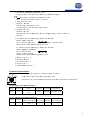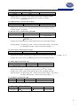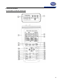
1
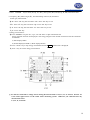
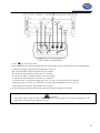
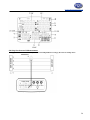
www.pce-industial-needs.com
Tursdale Technical Services Ltd
Unit N12B
Tursdale Business Park
Co. Durham
DH6 5PG
United Kingdom
Phone: +44 ( 0 ) 191 377 3398
Fax: +44 ( 0 ) 191 377 3357
[email protected]
http://www.industrial-needs.com/
Manual
PCE-360 power analyzer
[email protected]
CONTENTS
Title
Page
I.
SAFETY INFORMATION .................................................................................................................... 1
II.
INTRODUCTION FEATURE ......................................................................................................... 4
III. SPECIFICATIONS ....................................................................................................................................................... 4
3-1 Environment Conditions .........................................................................................................................................................................................................................................4
3-2 Safety Specifications .......................................................................................................................... 5
3-3 General Specification ...................................................................................................... 5
3-4 Electrical Specification ...................................................................................................................... 7
IV. PARTS & CONTROLS ..................................................................................................................... 10
4-1 Description of Parts & Control keys ................................................................................................... 10
4-2 Description of Display ...............................................................................................................................................................................................................................................12
V.
OPERATING INSTRUCTION ........................................................................................................ 15
5-1 AC Current Adaptor ............................................................................................................................ 15
5-2 Single-Phase 2-Wire (1P2W) Power System Measurement ...........................................................................17
5-3 Single-Phase 3-Wire (1P3W) Power System Measurement ............................................................... 20
5-4 Three-Phase 3-Wire (3P3W) Power System Measurement ................................................................ 23
5-5 Three-Phase 4-Wire (3P4W) Power System Measurement ................................................................ 26
5-6 Only One Current I4 Measurement ........................................................................................ 29
5-7 Manual Data Memory and Read Function Operation ........................................................................ 29
5-8 Auto Datalogging Function Operation ................................................................................................................................................30
5-9 Phase Sequence Measurement .............................................................................................................................................................................31
5-10 Voltage, Current Waveform and Harmonic Analyzer ................................................................ 31
5-11 Disable Auto Power Off Function .................................................................................................... 32
VI. MAINTENANCE ...............................................................................................................................................................32
6-1 General Maintenance ......................................................................................................................... 32
6-2 Battery Replacement .......................................................................................................................... 32
VII. RS-232 INTERFACE, SOFTWARE INSTALLATION AND OPERATION ................................... 33
2
[email protected]
1. SAF
FETY INFO
ORMATION
N
This Instru
uction Manu
ual providess information
n and warnings essentiial for opera
ating this me
eter in a saffe
manner an
nd for mainttaining it in safe operating condition. Before ussing this me
eter, be sure
e to carefully
read the fo
ollowing safe
ety information.
D
DANGE
ER
•
During high vo
oltage meassurement, in
ncorrect measurement procedures could result in injury or
e read this manual
m
care
efully and be
e sure that you
death, as well as damage to the metter. Please
c
beffore using the meter.
understand its contents
•
•
Do not
n use the meter or tesst leads if the
ey look dam
maged.
Use
e extreme caution
c
whe
en working around ba
are conducttors or bus bars, Accidental conta
act
with
h the conducctor could result in electrric shock.
To avoid
a
damag
ges to the meter,
m
do nott exceed the
e maximum limits of the input values
s shown in the
speccifications.
Use
e the meter only as specified in
n this man
nual, otherw
wise, the p
protection prrovided by the
meter may be im
mpaired.
D
DANGE
ER
•
•
SAFET
TY SYMBOL
LS
•
Caution refers to this manual before usin
ng the meterr.
•
This symbol is affixed
a
to th
he meter wh
here the op
perator shou
uld consult correspondiing
topicss before usin
ng relevant functions
f
of the meter.
•
This mark
m
indicattes explanattion, which is
i particularlly important that the use
er should re
ead
beforre using the meter.
•
Dang
gerous voltag
ges.
•
Meterr is prote
ected throu
ughout by double in
nsulation
When
n servicing, use only specified
s
re
eplacement parts.
•
Comp
ply with IEC61010-1, 2n
nd edition
o
or
reinforce
ed
insulatio
on.
3
[email protected]
DAN
NGER: Indicaates that incoorrect operatioon presents ex
xtreme dangeer of
acciddent resulting in death or serious injury to the user.
WA
ARNING: Inddicates that inncorrect operaation presentss significant danger
d
of acccident resultin
ng in death orr
seriious injury too the user.
CAU
UTION: Indicates that incorrect operatiion presents possibility
p
off injury to the user or damaage to the metter.
NOT
TE: Denotes ittems of advicce related to performance of
o the meter orr to its correcct operation.
NOTES ON
N USE
In order too ensure safe operation annd to obtain maximum
m
perfformance from the meter, observe the caution
c
listedd
below.
Installaation
CAUTIION
The metter is designeed for indoorr use and can be safely used at temperaatures ranging from 0℃ to
o 40℃.
Do not store or use the
t meter wheere it will be exposed to direct
d
sunlighht, high tempeerature, high humidity,
h
or
c
thhe meter may
y be damagedd, the insulation may deteeriorate, and
condenssation, if expoosed to such conditions,
the meteer may no lonnger satisfy itts specificatioons.
The metter does not construct
c
to bee waterproof or dustproof,, so do not use it in
a very dusty
d
environm
ment or in onne where will get wet.
Do not use
u the unit where
w
it may be exposed to corrosive or explosive
e
gass. The meter m
may be damaaged, or may
occur exxplosion.
Before use
WARNING
To preveent electric shhock, do not allow
a
the meteer to become wet and do not
n use the uniit when your hands are
wet.
When working with live circcuits, take all
a suitable precautions against accidents, includ
ding the use
g
such as rubber glovees, rubber boo
ots, and safetyy helmets.
of electrrical safety gear
Conneccting meter
WARN
NING
To prevent electric shhock, turn the power off before
b
conneccting the test leads and theen take measu
urements.
In orderr to prevent electrical
e
shocck and short – circuit accidents, shut off
o the powerr to the line to
o be measureed
before connecting
c
thee line to be measured
m
to thhe voltage inp
put terminals..
4
[email protected]
CAUTION
N
The meeasurement innput and synnchronizing input
i
are nott isolated froom each otheer. Connectiing either onne
means that
t
the otherr is exposed it is live, andd there is a danger
d
of electric shock. To avoid eleectrical shockk,
connect both terminaals.
WARNING
G
To avoid electrical shhock and / orr meter damaage, use cauttion when coonnecting testt leads to livee componentss.
A
makinng
The jaws of alligator clips can crreate a shoort circuit beetween closeely spaced liive parts. Avoid
c
o bus bars at elevated
or
d potentials. Whenever,
W
pllease make connections
c
t
to
connections to feeder conductors
a possible ass you can, wh
hich can proviide better shoort circuit pro
otection.
the outputt side of a circuit breaker as
Follow all
a legal requuirements.
Follow all
a instructionns in the mannuals.
Obey poosted instructtions.
Never assume that a circuit is de-eenergized, chheck it first.
Always set up the meeasurement fiirst, then connnect the test leads
l
to the ciircuit.
Removee all test leadss that are not in use.
Make coonnections too the meter firrst, before connnecting lead
ds to a live cirrcuit.
Connect the ground lead first, thhen the voltagge leads and the current probe,
p
Disconnnect in reverrse order.
Route teest leads carefully.
TION FEATUR
RE
II. INTRODUCT
The sympptoms of pooor power quality
q
includde intermitteent lock-ups and resets, corrupted daata, prematurre
equipmentt failure, oveer-heating off componentss for no appaarent cause, etc. The ultiimate cost iss in downtime,
decreased productivity and frustrateed personnel.
q
trouble shooting can help you
y
keep your power sy
ystem up annd
Use poweer analyzer to power quality
running, troubleshoott problems quickly, im
mprove poweer efficient, manage ennergy costs, zero in on
o
d
to desiggn
harmonicss, optimize power systeem performannce, improvee power quallity and analyyze system data
optimal uppgrades.
10 displaay Easy-to-viiew LCD screeen, and is caapable of show
wing many power quality parameters at
a the same
time.
4 currennt probe including for measuring a neuttral line curren
nt.
Measurees single-phasse 2-wire, sinngle-phase 3-w
wire, three-ph
hase 3-wire and
a three-phase 4-wire sysstems.
All Truee-RMS sensinng , V, A, KW
W, KVAR, KV
VA, PF, θ, Hz, KWh, KVAR
Rh and
KVAh measurement
m
s.
Phase seequence indiccator functionn.
Backlighht display funnction.
Manual Data Memorry and Read (99 sets).
Data loggging (504K byte
b memoryy, 12,000 sets per block, total 20,000 setts).
RS-232 optical interfa
face with threee phase voltagge / current waveform
w
dispplay and harm
monic analysiis.
Easy-to--use key operration.
Light weeight and porrtable design.
5
[email protected]
III. SPECIFIC
CATIONS
3-1 Enviro
onment Con
nditions:
Altituude up to 20000 meters
Indooor use only
Relattively humidiity 80% max.
Operration ambiennt 0~40℃
y Specifications
3-2 Safety
Categoryy Rating : 10000V Measureement Categoory III, Polluttion Degree 2.
2
: IE
EC 61010-1 2nnd Edition
CAT III : Measuremeent category in
i which meaasurements peerformed in thhe building innstallation.
C
ics :
Safety Characteristi
Current Clamps, Moddel PCE AC3360, to be useed only with the
t Three-Phaase Power Annalyzer, Mod
del PCE-360.
peration and to
t
This maanual containss informationn and warningg that must bee followed byy the user to eensure safe op
keep thee meter and itts accessoriess in a safe conndition.
Use of thhis meter andd its accessoriies in a mannner not specifiied by the maanufacturer m
may impair thee
protectiion provided by
b the equipm
ment.
Equipmeent operationn, the responsible body shaall be made aw
ware that, if the
t equipmennt is used in a manner not
specifieed by the mannufacturer, thee protection provided
p
by th
he probe asseembly may bee impaired.
3-3 General Specifica
ation
Maximuum voltage beetween voltagge input termiinals and eartth ground:
1000 Vrrms
Maximuum rated workking voltage for
f current innput: 0.35 Vrm
ms
Maximuum current forr current probbe: 1000 Arm
ms
Numericcal 10 displayy: 10 display 4 digit LCD maximum reaading 9999.
Battery life:
l
approx. 50
5 hours.
Auto pow
wer off: apprrox. 30 minutes.
Low batttery indicatioon: the BT is
i displayed when
w
the batteery voltage drops
d
below thhe operating voltage.
v
Backlighht display tim
me: Auto off approx.
a
30 secconds.
Samplinng rate : Approx. 1 time peer 2 seconds (Digital
(
displaay).
Waveforrm and harmoonic analyzerr: 64 samples per period.
Current probe jaw oppening diametter: Cablesψ
ψ40mm.
Operatinng temperaturre: 0°C to 40°C
Operatinng humidity: Maximum
M
relative humidiity of 80% fo
or temperaturees up to
31°C decrease linearly to 50% relativee humidity at
40°C (non-coondensed).
Temperaature coefficieent : 0.1 ⋅ (sppecified accuuracy)/ °C (<1
18 or >28°C)
Storage temperature and
a humidityy: -10°C to 600°C
R.H. < 70%
% non-conden
nsed.
Dimensionns: Meter → 235(L)⋅117((W)⋅54(H)m
mm.
Current probe
p
→ 193(L)⋅88(W)⋅440(H)mm.
Weight: Meter
M
includinng battery → approx. 730gg
C
Current
probee → approx. 333g
3
Accessoriie:
6
[email protected]
1. PCE-360 AC
C CURRENT
T ADAPTOR x 4pcs
Category Raating : CAT IIII 600V per IE
EC61010-1, Pollution
P
Deggree2.
: IEC 611010-1 2nd Edition
E
and IE
EC61010-2-03
32
Input : AC 1000A maxim
mum. Output : 0.35mV/A
2. Voltage test lead x 4pcs
T 202I
Model no : TL
Manufactureer : Hong Kaii Co., Ltd.
Category Raating : CAT IIII, 1000V, AC
C 10A Max.
3.. Alligator cliip x 4pcs
Model no : FC-A23
F
Manufactureer : Fu Chyi Enterprise
E
CO
O., Ltd. Categ
gory Rating : CAT III, 10000V, AC
10A Max.
4.. AC Adaptorr (IN-OUT Isoolated type, Input
I
120V AC
A 60Hz
Model : MW
W35-12003000
Input : 120V
V AC 60Hz 6..1W
C 300mA
Outtput : 12V DC
Manufactureer : MAW WO
OEI Enterprisse CO., Ltd.
AC Adaptor (IN-OUT Isoolated type, Innput 230V AC
C 50Hz
WD48-12003000GS
Model : MW
Input : 230V
V AC 50Hz
Output : 12V
V DC 300mA
A
Manufactureer : MAW WO
OEI Enterprisse CO., Ltd.
5.. Battery 1.5V
V “AA” ⋅ 8
6.. Instruction manual
m
⋅1
7.. PC softwaree CD-R ⋅ 1
8.. Carrying casse ⋅ 1
9. Optical RS2232 interface ⋅ 1
3-4 Electrrical Specifiication
Acccuracy: ±(% of reading + number of digits)
d
at 18℃
℃ to
28℃
℃ ( 64℉ to 82℉)
8
with rellative humiditty to 80%.
The current error is specified within
w
the largest circle whhich can be ddrawn inside the
t jaw.
AC Vooltage Trms measuremen
m
nt (V) :
Range
R
Resolution
Accuracy
Input
impedancce
Overload
d
protection
n
Nominal power
system freequency
999.9V
0.1V
±((0.3%rdg±10dggts)
(>50V)
2MΩ
1000Vrm
ms
Only 50Hzz or 60Hz
Displaay item : RMS voltage vallue for each channel.
c
AC Cu
urrent Trms Measurement (A) :
Range
R
Resolution
999.9A
0.1A
Accuracy
Curreent
Overloaad
Nominall power
probe output protection system frequency
(inclluding current probe)
p
±(0.5%rdg±15dggts)
0.35mV
V/A 1000Arm
ms Only 50Hzz or 60Hz
(>3A)
Displaay item : RMS current valuue for each chhannel.
7
[email protected]
Active Power measurement P (KW) :
Range
999.9KW
Resolution
0.1KW
Accuracy
±1.0%rdg±20dgts
Display items : Active power of each channel and its sum of multiple channels.
Polarity display : For influx (consumption) No symbol, For outflow
(regenerative) “ - ”.
Apparent Power measurement S (KVA) :
Range
999.9KVA
Resolution
0.1KVA
Accuracy
±1.0%rdg±20dgts
Measurement method : Calculate from RMS voltage U and RMS current I.
Display item : Apparent power of each channel and its sum of multiple channels.
Polarity display : No polarity.
Reactive Power measurement Q (KVAR) :
Range
Resolution
Accuracy
999.9KVAR
0.1KVAR
±1.0%rdg±20dgts
Measurement method : Calculate from apparent power S and active power P,
2
2
Q= S
P .
Display item : Reactive power of each channel and its sum of multiple channels.
Polarity display : For phase lag (LAG : current is slower than voltage) : No symbol.
For lead phase (LEAD : current is faster than voltage) : “-”
Power Factor measurement (COSψ) :
Range
0 ~ +1
Resolution
0.001
Calculated Accuracy
±3dgt
Measurement method: Calculate from apparent power S and active power P, PF = COSψ= P / S
Display item: Power factor of each channel and its sum of multiple channels.
Phase angle measurement (ψ) :
Range
Resolution
Calculated Accuracy
+90°~ 0°~ -90°
0.1°
±3dgt
Measurement method : Calculate from power factor COSψ ,ψ= COSPF.
Display item : Phase angle of each channel and its sum of multiple channels.
Polarity display : For phase lag (LAG : current is slower than voltage) : No symbol.
For phase lead (LEAD : current is faster than voltage) : “-”.
Frequency measurement (Hz) :
Range
60HZ
Resolution
0.1Hz
Accuracy
±0.1%rdg±2dgt
Measurement source
Voltage U1 > 50V
Measurable input range : > 50V
Three Phase Sequence Detection :
Input voltage range Normal phase indication Reverse phase indication Measurement source
3P > 50V
U1, U2 and U3
8
[email protected]
Active Power Energy measurement (KWh) :
Range
Resolution
Active power
accuracy
Timer interval
Timer Accuracy
3.999KWh
39.99KWh
399.9KWh
3.999MWh
39.99MWh
119.3MWh
0.001KWh
0.01KWh
0.1KWh
0.001MWh
0.01MWh
0.1MWh
±1.0%rdg±20dgt
1 sec
±50ppm (25℃, 77℉ )
Measurement display : Display all active power consumption energy (sum of absolute values).
Apparent Power Energy measurement (KVAh) :
Range
Resolution
Apparent power
accuracy
Timer interval
Timer Accuracy
3.999KVAh
39.99KVAh
399.9KVAh
3.999MVAh
39.99MVAh
119.3MVAh
0.001KVAh
0.01KVAh
0.1KVAh
0.001MVAh
0.01MVAh
0.1MVAh
±1.0%rdg±20dgt
1 sec
±50ppm (25°C, 77°F)
Measurement display : Display all apparent power energy (sum of absolute
values).
Reactive Power Energy measurement (Kvarh) :
Range
Resolution
3.999Kvarh
0.001Kvarh
39.99Kvarh
0.01Kvarh
399.9Kvarh
0.1Kvarh
3.999Mvarh
0.001Mvarh
39.99Mvarh
0.01Mvarh
119.3Mvarh
0.1Mvarh
Reactive power
accuracy
Timer interval
Timer Accuracy
±1.0%rdg±20dgt
1 sec
±50ppm (25°C, 77°F)
Measurement display : Display all reactive power consumption (sum of
absolute values).
Harmonic measurement (use only PC on line analyzer)
Order
Accuracy
Harmonic Source
No. of samples per period
1 ~ 31
±3%THD
U1, U2, U3 > 80V
I1, I2, I3 > 50A
64
Waveform (use only PC on line displayed)
Select phase A, B or C.
Select Voltage and current waveform output.
9
[email protected]
IV. PARTS & CONTROLS
4-1 Description of Parts & Control keys
10
[email protected]
1. Input
I
for volltage termina
als (U1, U2, U3,
U N).
2. Input forr current proobe jacks (I11, I2, I3, I4).
3. Plug for external AC
C adaptor pow
wer supply input.
4. Optical RS232
R
interfface output.
5. LCD disp
play.
6. WIRING
G key : Selecct the type off electrical syystem under teest, press WIIRING key too select 1P2W
W (To measurre
singlee-phase two-w
wire power liines), 1P3W (To
( measure single-phase
s
tthree-wire po
ower lines),
3P3W
W2M (To measure
m
threee-phase threee-wire pow
wer line without neutral, using the tw
wo
powerr meter methhod, use this when measu
uring three-pphase powerr with 2-cu
urrent probe
measuurement onlyy.) and 3P4W
W (To measuree three-phasee four- wire ppower lines with
w neutral)
electrrical system inn cycles.
7.
keyy : Phase sequuence detectionn function keyy. In a 3P4W mode,
m
press annd hold
down this key,
k it will dissplay phase deetection resultts as follows : Normal phasse
Reverse phhase
8. HOLD key
k : Data holld function keey, press HOL
LD key to ho
old data, the HOLD
H
annunciattor is displaayed, press HOLD
H
key again
a
to exitt Hold functiion.
Press andd hold downn HOLD key then press
key turn on
o the meter,, the “
exit auto power off fuunction.
” mark
m
disappeaar,
9.
key : Backlight fuunction key, press
p
keyy to turn on an
nd off of backklight.
The backklight will sw
witch off autom
matically afteer 30 secondss.
10. PF key : Display measured powerr factor valuee control key, the PF annunnciator
is displaayed.
11. Θ key : Display meaasured phase angle
a
value control
c
key, th
he ψ annunciiator is displaayed.
12. Hz key : Display meeasured frequeency value coontrol key, thee Hz annunciiator is displaayed.
ontrol key, the
t
I4
13. I4 keyy : Display measured I44 current proobe value co
annunciattor is displayeed.
14. SET keey : Setting current date and
a time funcction key, preess SET key to
t enter curreent time settin
ng mode andd
me setting moode for auto datalogging
d
use.
u
interval tim
15 TIME key
k : Displayy current datee and time coontrol key, prress and holdd down
TIME
E key display current data and time.
∝ Keys
K
: Setting current date and
a time, or recall
r
manuall data memorry to read mem
mory data in cycles
k
control keys.
RT key : Startt auto dataloggging functionn.
17. STAR
18. STOP
P key : Stop auto
a
dataloggiing function. Press STAR
RT key to resuume recordingg in current data
d sets.
19. MEM
MORY key : Manual dataa memory conntrol key. Prress MEMOR
RY key each time to sttore one seet
c
current
dispplay reading into the memory,
m
the M annunciator and the memorry
address numbber is displayyed, total mem
mory size is 99
9 sets.
20. READ
D key : Read manual mem
mory data conttrol key.
21. POW
WER Keyy : Display meeasured poweer value contrrol key, the Pt123, Qt123 aand St123 annunciators will
be displayedd in cycles.
22. ENER
RGY key : Diisplay total inntegrated pow
wer energy vaalue control key,
k the three h annunciatorrs will be
diisplayed.
16.
23. KEY Lock
L
key : Lock
L
all the fuunctions key, except
LOCK annuncciator is displaayed.
24.
and
a
keys,, the
key : Power on-off control key.
k
11
[email protected]
4-2 Description of Display
: Auto power off indication.
HOLD : Display hold mode.
LOCK : Set key lock mode.
BT : Low battery indication.
ψ: Phase angle display.
: Phase angle unit.
1P2W : Measure single-phase two-wire power line indication.
1P3W : Measure single-phase three-wire power line indication.
3P3W2M : Measure three-phase three-wire power line indication.
3P4W : Measure three-phase four-wire power line indication.
P1 : Phase 1 active power measured display indication.
P2 : Phase 2 active power measured display indication.
P3 : Phase 3 active power measured display indication.
Pt: Total active power measured display indication and total active energy measured display indication.
KW : Active power unit.
KWh, MWh : Active energy unit.
PF1: Phase 1 power factor measured display. PF2: Phase 2 power factor
measured display. PF3: Phase 3 power factor measured display. PFt: Total
power factor measured display.
I4 : Current probe 4 current measured display.
Hz : Frequency unit.
DATA No.⋅⋅ : Last manual datalogged memory address number indication (01~99).
M : Manual datalogged indicate on, M displays one time store one sets data into the memory.
DATA R No.⋅⋅ : Recall manual datalogged address number indication, the
memory data displayed for read.
DATA M ⋅⋅ : Auto datalogging indication, M disappears one time store one sets data into the memory .
01 ~ 10 : Maximum 10 memory blocks can be use, only 12,000
sets data can be stored in one block. Maximum 20,000 sets data can be stored.
FF : Memory full indication, if exceed 10 memory blocks or exceed 20,000 stored data.
12
[email protected]
Q1 : Phasee 1 reactive power measuured display indication. Q2
Q : Phase 2 reactive power
measured diisplay indicattion. Q3 : Phaase 3 reactivee power meassured display indication.
Qt : Total reeactive powerr measured display
d
indicattion and totall reactive eneergy measuredd display indiication.
Kvar : Reacctive power unit.
u
Kvarh, Mvvarh : Reactivve energy uniit.
S1 : Phase 1 apparent power measuured display indication. S2 : Phase 2 apparent ppower
measured diisplay indicattion. S3 : Phaase 3 apparennt power meassured displayy indication.
St : Total appparent power measured display
d
indicaation and totall apparent eneergy measureed display ind
dication.
KVA : Appaarent power unit.
u
KVAh : Apparent eneergy unit. MV
VAh
: Apparent energy
e
unit.
TIME : Current data andd time indicattion.
m : Date andd time displayyed.
Y-M D-h m-s
INTV : Autto dataloggingg interval tim
me setting indication.
START : Energy calculaating start tim
me indication.
STOP : Eneergy calculatiing stop time indication.
U1, V, A : 1P2W
1
phase U1
U voltage annd current proove I1 measu
ured display inndication.
U1, V, A, U2,
U V, A : 1P3W phase U1,, U2 voltage and
a current probe I1, I2
meaasured displayy indication.
U12, V, I1, A, U23, V, I22, A : 3P3W22M phase U122, U23 voltag
ge and currennt probe I1, I22 measured diisplay
indicatiion.
U V, A, U3, V,
V A : 3P4W phase U1, U22, U3 voltagee and current probe I1, I2, I3 measured
d display
U1, V, A, U2,
indicattion.
V : Voltage unit.
A : Current unit.
1000V : Volltage range inndication.
250A, 500A
A, 1000A : Cuurrent range indication
i
(A
Autoranging)
V. OPERAT
TING INSTRU
UCTION
N
CAUTION
If possible, before connecting the
t meter to the electricaal equipment to be tested,, take off the electrical
equipmeent’s power.
DANGER
R
Voltagee input connectors U1 to U3
U are comm
mon for input connector N,
N each input cconnectors arre not
insulateed.
Do not connect
c
the unnecessary
u
n
number
of corrds.
WARNING
G
Always set up the meeasurement first,
fi
then connect the test leads
l
to the circuit.
Make connections
c
t the instrum
to
ment first, beefore connectting leads to a live circuitt.
Connecct the ground lead first, thhen the voltagge leads and the current probe,
p
Disconnnect in reverrse order.
Removee all test leads that are not in use.
13
[email protected]
※ U1 must be conneccted to voltagge source du
uring the mea
asurement of
o U2, U3, I1, I2 and I3, because U1
U
m
measu
uring system
m. Otherwisee you could not have an
ny
is the main signall source of the whole meter
m U2, U3, I1, I2 and I3.
measurrement from
5-1 AC Cu
urrent Adap
ptor
Safety In
nformation
Reead First: Saafety Inform
mation
To ensuure safe operattion and servicce of the curreent clamp, folllow these insttructions:
Read the operatingg instructions before use annd follow all safety instrucctions.
Use the Current Clamp onlyy as specifieed in the op
perating instrructions, otheerwise the claamp’s safety
p
you.
featuures may not protect
Adhere to local and
a national safety codess. Individuaal protective equipment m
must be useed to prevennt
uctors are expposed.
shockk and arc blaast injury whhere hazardous live condu
Do noot hold the Currrent Clamp anywhere
a
beyoond the tactilee barrier, see Figure
F
1.
Beforre each use, inspect the Current Clam
mp. Look for cracks or misssing portionss of the clamp
p housing or
outpuut cable insulaation. Also loook for loosee or weakened
d componentss. Pay particuular attention to the
insulaation surrounding the jawss.
Never use the clam
mp on a circuuit with voltagges higher thaan 600V CAT
T III.
Use extreme
e
cautioon when workking around bare
b conducto
or or bus bars. Contact withh the conducttor could resuult
in elecctric shock.
Use caution
c
when working withh voltages above 60V or 30V ac. Suchh voltages posse a shock hazzard.
Warning
W
To avooid possible electric
e
shockk or personal injury:
i
Befoore each use, inspect thee Current Claamp. Look for cracks orr missing porrtions of the clamp housinng
and ouutput cable insulating coveer and for looose
or weeakened com
mponents. Payy particular attention to
o the insulaation surrounnding the clam
mp jaws.
Do not
n use a dam
maged Currennt Clamp. If a clamp is daamaged, tape it shut to preevent uninten
nded operationn.
Measu
urement Con
nsiderations
Centter the conducctor inside the Current Claamp jaw.
Makke sure the claamp is perpenndicular to thee conductor.
For optimal readding, make sure the connductor is po
ositioned bettween the alignment mark
ks on the jawss of
the Cuurrent Clamp.
Observve the follow
wing guidelinees when makiing measurem
ments :
Avoiid taking meaasurements cloose to other current
c
carrying conductorrs.
14
[email protected]
Operation
To use the AC Currentt Adaptor, reefer to “Meassurement Con
nsiderations”” and
Figure 1.
1. Connect the clamp caable to the insstrument.
2. The arroow on the top of the clamp must face towards the loaad of the circuuit.
3. Connect the current clamp
c
jaws arround the connductor to be measured.
W
Warning
p
injurry, keep fingeers behind th
he tactile barrrier, see
To avoidd shock or personal
Figure 1.
1
5-2 Single
e-Phase 2-W
Wire (1P2W)) Power Sys
stem Measu
urement
Applicatiion :
R
Receptacle
brranch circuit
Lightting loads
Troublesshooting electriccal distribution system.
M
Measuring
curreent harmonic (use PC).
Measurinng line rms volttage.
M
Measuring
poweer on single phaase loads.
Measurinng line rms currrent.
Measurinng frequency.
Measurinng voltage harm
monics (use PC)).
Measurinng current harm
monics (use PC)).
Measurinng voltage wavveform (use PC)).
Measurinng current waveeform (use PC))
Measurinng the load on a transformer.
Recordinng the load on a transformer.
15
[email protected]
A : Line, N : Neutral, G : Ground,
Face the arrow toward the load.
1P2W Wiring Connection Diagram
1. Press
key to turn on the meter.
2. Press WIRING key to select the 1P2W electrical system under test, the 1P2W annunciator will be displayed.
3. Connect the voltage test leads and current probe to the meter.
Connect the black voltage test lead to the “N” terminal.
Connect the red voltage test lead to the “U1” terminal.
Connect the I1 current probe output plug to the “I1” jack.
If you want to measure ground leakage current, connect the I4 current probe output plug to the “I4” jack.
4. Connect the voltage test leads and current probe to the electrical equipment to be tested.
CAUTION
If possible, before connecting the voltage test leads and current probe to the electrical equipment to be
tested, take off the electrical equipment’s power.
Connect the black voltage test alligator to the Neutral Line “N”.
Connect the red voltage test alligator to the Line “A”.
Press I1 current probe trigger to open the jaw and fully enclose the Line “A”. If you want to measure ground
leakage current, press I4 current probe the trigger to open the jaw and fully enclose the Ground Line “G”.
5. Frequency (Hz), Phase Angle (Θ ), Ground Leakage Current (I4) and Power
Factor (pF) measurement :
Hz : Press “Hz” key, PF1 will show “Hz”. Press “PF” key to exit.
Θ : Press “Θ ” key, PF1 will show “ψ”. Press “PF” key to exit.
I4 : Press “I4” key, PF1 will show “I4”. Press “PF” key to exit.
pF : Press “PF” key.
6. Energy measurement:
Press “ENERGY” key, the “Pt”, “Qt”, “St” and “PFt” or “ψt” annunciator
and energy integrate start time are displayed. The energy integrate value and the current time will be continuous
accumulate.
a). KW displays KWh
b). KVAR displays KVARh c). KVA displays KVAh
16
[email protected]
Press “ STOP” key to stop energy accumulated and the HOLD annunciator is displayed.
Press ∝ key to exit the energy measurement.
※ U1 must be connected to voltage source during the measurement of U2, U3, I1, I2 and I3, because U1
is the main signal source of the whole meter measuring system. Otherwise you could not have any
measurement from
U2, U3, I1, I2 and I3.
5-3 Single-Phase 3-Wire (1P3W) Power System Measurement
Application : Same as 1P2W power system measurement.
A, B : Line, N : Neutral, G : Ground,
Face the arrow toward the load.
17
[email protected]
1. Press
key to turn on the meter.
2. Press WIRING key to select the 1P3W electrical system under test, the 1P3W annunciator will be displayed.
3. Connect the voltage test leads and current probe to the meter.
Connect the black voltage test lead to the “N” terminal.
Connect the red voltage test lead to the “U1” terminal.
Connect the yellow voltage test lead to the “U2” terminal.
output plug to the “I1” jack.
Connect the I1 current probe
Connect the I2 current probe output plug to the “I2” jack.
If you want to measure ground leakage current, connect the I4 current probe output plug to the “I4” jack.
4. Connect the voltage test leads and current probe to the electrical equipment to be tested.
CAUTION
If possible, before connecting the voltage test leads and current probe to the electrical equipment to be
tested, take off the electrical equipment’s power.
Connect the black voltage test alligator to the neutral line “N”.
Connect the red voltage test alligator to the line “A”.
Connect the yellow voltage test alligator to the line “B”.
Press I1 current probe trigger to open the jaw and fully enclose the Line “A”.
11
Press I2 current probe trigger to open the jaw and fully enclose the Line “B”.
12
If you want to measure ground leakage current, press I4 current probe trigger
to open the jaw and fully enclose the ground line “G”.
18
[email protected]
5. Press
POWER
key to select (P1, Q1, S1, PF1), (P2, Q2, S2, PF2) and (Pt, Qt, St, PFt) measured values.
6. Frequency (Hz), Phase Angle (Θ ), Ground Leakage Current (I4) and Power
Factor (pF) measurement :
Hz : Press “Hz” key, PF1 will show “Hz”. Press “PF” key to exit.
Θ : Press “Θ ” key, PF1 will show “ψ”. Press “PF” key to exit.
I4 : Press “I4” key, PF1 will show “I4”. Press “PF” key to exit.
pF : Press “PF” key.
7. Energy measurement :
Press “ENERGY” key, the “Pt”, “Qt”, “St” and “PFt” or “ψt” annunciator and
energy integrate start time are displayed. The energy integrate value and the current time will be continuous
accumulate.
a). KW displays KWh
b). KVAR displays KVARh c). KVA displays KVAh
Press “ STOP ” key to stop energy accumulated and the HOLD annunciator is displayed.
Press ∝ key to exit the energy measurement.
※ U1 must be connected to voltage source during the measurement of U2, U3, I1, I2 and I3, because U1
is the main signal source of the whole meter measuring system. Otherwise you could not have any
measurement from
U2, U3, I1, I2 and I3.
19
[email protected]
5-4 Three-Phase 3-Wire (3P3W) Power System Measurement
Application :
Induction motors without adjustable speed drive. Induction motors with adjustable speed drive.
Checking voltage unbalance.
Checking current on phases.
Checking current and current unbalance.
Measuring frequency of motor current.
Measuring power in 3-phase balanced and
unbalanced system.
Measuring power factor of 3-phase motors.
Measuring voltage harmonics (use PC).
Unbalance factor :
When the load of the specified phase becomes too heavy due to fluctuations in loads connected to each power
line phases, or when operating on uneven device, the voltage and current waveforms become distorted, causing
voltage drops, they can cause voltage unbalance, reverse phase to neutral voltage, and harmonics may cause
accidents such as uneven motor rotation, circuit breaker trips, and over load heating in the transformer.
1. Press
key to turn on the meter.
2. Press WIRING key to select the 3P3W2M electrical system under test, the 3P3W2M annunciator will be
displayed.
3. Connect the voltage test leads and current probe to the meter.
Connect the black voltage test lead to the “N” terminal.
Connect the red voltage test lead to the “U1” terminal.
Connect the yellow voltage test lead to the “U2” terminal.
output plug to the “I1” jack.
Connect the I1 current probe
Connect the I2 current probe output plug to the “I2” jack.
4. Connect the voltage test leads and current probe to the electrical equipment to be tested.
20
[email protected]
CAUTION
If possible, before connecting the voltage test leads and current probe to the electrical equipment to be
tested, take off the electrical equipment’s power.
Connect the black voltage test alligator to the line “B”.
Connect the red voltage test alligator to the line “A”.
Connect the yellow voltage test alligator to the line “C”.
Press I1 current probe trigger to open the jaw and fully enclose the Line “A”.
Press I2 current probe trigger to open the jaw and fully enclose the Line “C”.
5. Press
POWER
key to select (P1, Q1, S1, PF1), (P2, Q2, S2, PF2) and (Pt, Qt, St, PFt) measured values.
6. Frequency (Hz), Phase Angle (Θ ) and Power Factor (pF) measurement:
Hz : Press “Hz” key, PF1 will show “Hz”. Press “PF” key to exit.
Θ : Press “Θ ” key, PF1 will show “ψ”. Press “PF” key to exit.
pF : Press “PF” key.
7. Energy measurement:
Press “ENERGY” key, the “Pt”, “Qt”, “St” and “PFt” or “ψt” annunciator
and energy integrate start time are displayed. The energy integrate value and the current time will be continuous
accumulate.
a). KW displays KWh
b). KVAR displays KVARh c). KVA displays KVAh
Press “ STOP ” key to stop energy accumulated and the HOLD annunciator is displayed.
Press ∝ key to exit the energy measurement.
5-5 Three-Phase 4-Wire (3P4W) Power System Measurement
Application : Same as 3P3W power system measurement.
21
[email protected]
1. Press
key to turn on the meter.
2. Press WIRING key to select the 3P4W electrical system under test, the 3P4W annunciator will be displayed.
3. Connect the voltage test leads and current probe to the meter.
Connect the black voltage test lead to the “N” terminal.
Connect the red voltage test lead to the “U1” terminal.
Connect the yellow voltage test lead to the “U2” terminal.
Connect the blue voltage test lead to the “U3” terminal.
Connect the I1 current probe output plug to the “I1” jack. Connect the I2 current probe
output plug to the “I2” jack. Connect the I3 current probe output plug to the “I3” jack.
Connect the I4 current probe output plug to the “I4” jack.
4. Connect the voltage test leads and current probe to the electrical equipment to be tested.
CAUTION
If possible, before connecting the voltage test leads and current probe to the electrical equipment to be
tested, take off the electrical equipment’s power.
22
[email protected]
Connect the black voltage test alligator to the neutral line “N”.
Connect the red voltage test alligator to the line “A”.
5. Press POWER
measured values.
key to select (P1, Q1, S1, PF1), (P2, Q2, S2, PF2), (P3, Q3, S3, PF3) and (Pt, Qt, St, PFt)
6. Frequency (Hz), Phase Angle (Θ ), Neutral Line Current (I4) and Power Factor
(pF) measurement :
Hz : Press “Hz” key, PF1 will show “Hz”. Press “PF” key to exit.
Θ : Press “Θ ” key, PF1 will show “ψ”. Press “PF” key to exit.
I4 : Press “I4” key, PF1 will show “I4”. Press “PF” key to exit.
pF : Press “PF” key.
7. Energy measurement:
Press “ENERGY” key, the “Pt”, “Qt”, “St” and “PFt” or “ψt” annunciator
and energy integrate start time are displayed. The energy integrate value and the current time will be continuous
accumulate.
a). KW displays KWh
b). KVAR displays KVARh c). KVA displays KVAh
Press “ STOP ” key to stop energy accumulated and the HOLD annunciator is displayed.
Press ∝ key to exit the energy measurement.
23
[email protected]
5-6 Only One Current I4 Measurement
Application : Measurement any wire current independent of voltage, the same as clamp meter
application.
24
[email protected]
1. Press
key to turn on the meter.
2. Press “I4” key.
3. Connect the I4 current probe output plug to the “I4” jack.
4. Press I4 current probe trigger to open the jaw and fully enclose desired measured wire.
5. Read the I4 value, if the measured current value greater than 250A, the display will show the “OL” symbol.
5-7 Manual Data Memory and Read Function Operation
1. Clear memory data :
Press
key to turn off the meter.
Press and hold down the MEMORY key then press
displayed and all manual memories data is cleared.
2. Store Manual data to memory :
key again to turn on the meter, the “CLr” annunciator is
Press MEMORY key one time store one sets displayed data to memory, the
annunciator display one time and the stored memory address will be displayed.
Maximum store memory capacity size is 99 sets.
3. Read the manual stored data :
Press READ key to enter the read mode, the
annunciator is displayed.
Press
key to read the memories data, the memories data address will be displayed.
Press “ ∝ ” key to exit the read mode.
5-8 Auto Datalogging Function Operation
1. Clear memory data :
Please refer to software manual (CD-ROM), use PC to clear memories data, the meter can not clear memories
data free from lost memories data.
2. Store Auto datalogging data to memory :
Setting the current time and Auto datalogging interval time.
Press SET key to enter current time setting mode.
Press keys to set actual current YEAR-month, DAY-hour, minute- second.
Press ∝ key to enter auto datalogging interval time setting, the “INTV” annunciator is displayed.
Press keys cycle select the interval time, you can select 5 seconds, 30 seconds, 1 minute or 2 minutes.
Press ∝ key to exit TIME setting mode.
Enter Auto datalogging mode.
Press START key to start Auto data logging, the DATA M⋅ will be displayed, the M annunciator, according to
the interval time disappear one time store one sets data into the memory.
Press STOP key to stop data record, press START key will resume data record, but maximum can be divide to
10 memory blocks, only 12,000 sets data can be stored in one block, the current block number will be
displayed, total maximum record capacity size is 20,000 sets data.
When maximum block or maximum capacity is full, the “FF” annunciator will be displayed, the data
record is auto stopped.
Download data to PC
Please refer to the software manual (CD-ROM) to download the data.
25
[email protected]
5-9 Phase Sequence Measurement
1. Press
key to turnn on the meteer.
2. Press WIRING
W
key to
t select 3P4W
W mode.
3. Connecct the voltage test leads to the meter.
Connnect the red vooltage test leaad to the “U1”” terminal.
Connnect the yellow
w voltage testt lead to the “U2”
“
terminaal.
Connnect the blue voltage
v
test leead to the “U33” terminal.
4. Connecct the voltage test leads to the electricall equipment to
o be tested.
CAUTIO
ON
If possible,
p
befoore connectinng the voltagee test leads an
nd current prrobe to the ellectrical equip
pment to be
testted, take off the
t electrical equipment’ss power.
Connnect the red vooltage test alligator to the power
p
line “A
A” phase.
Connnect the yellow
w voltage testt alligator to the
t power lin
ne “B” phase.
Connnect the blue voltage
v
test allligator to thee power line “C”
“ phase.
5. U1, U2 and U3 meassured voltagee must be greaater than 30V
V, then press and
a hold dow
wn “
wires iss normal phasse, the “
” keey. If connecttion
” annunciatorr
is displayed. If connnection wiress is reverse phhase, the “
” annunciaator is displayyed. Release the “
”
key to exit
e this meassurement.
5-10 Volta
age, Currentt Waveform
m and Harm
monic Analyzer
Applicaation :
May device
d
powerr sources noow use sem
miconductor control
c
devicces and harm
monics occur because of
distorteed voltage or current wavee forms.
When harmonic
h
com
mponents becoome too largee, they can cause serious acccidents, suchh as transformer supplyinng
seemingg average looads are oveerheating, neutral conducctors in ballanced circuuit are overrheating from
m
exceesiing loads, ciircuit breakerrs are trippinng for no app
parent reasonn, overheatingg the motor or
o burning ouut
the reacctor connected to the phase advance cappacitor.
Please refer to
t software manual
m
(CD-R
ROM) for wavveform and harmonic
h
meaasurement.
5-11 Disab
ble Auto Po
ower Off Fu
unction
The meeter will automatically entter sleep modde approx. 30 minutes to saave power coonsumption.
1. Disablee auto power off
o proceduree :
Press
key to turn
t
off the meter.
m
Press and hold dow
wn HOLD keey, then press
disablled, and the auto
a
power offf symbol “
urn on the metter, the auto ppower functio
on will be
key to tu
” will bee disappear.
2. Auto poower off modde is enabled each
e
time youu turn on the meter and is automaticallyy disabled as the
follow modes.
m
ENER
RGY functionn is active.
Auto datalogging function
f
is acctive.
PC linnked.
2
26
[email protected]
VI. MAINTENANCE
6-1 General Maintenance
1. Repairs or services that are not covered in this manual should only be performed by qualified personnel.
2. Clean the meter and accessories with a damp cloth and a mild soap. Do not use abrasives, solvent, or alcohol.
These may damage the text.
3. Additional to this it is recommended to open the jaws of the Current Clamp and
to wipe the magnetic pole pieces with a lightly oiled cloth. This in order to avoid rust or corrosion to form on
the magnetic poles.
6-2 Battery Replacement
WARNING
To AVOID electrical shock, remove the test leads and current probe before replacing the batteries.
1. As battery power is not sufficient, LCD will display y BT annunciator, replace new battery is required.
2. Disconnect all test leads and current probe from any power electrical source, press
key to turn off the
meter, and remove the test leads from the jacks.
3. The battery cover is secured to the bottom case by two screws. Using a screw
drive to remove the two screws from the bottom case.
4. Remove battery cover, take out the batteries and replace with new batteries.
(Please note battery polarity)
VII. RS-232 INTERFACE, SOFTWARE INSTALLATION AND OPERATION
For the detailed instruction, please refer to the content of attached CD-ROM,
which has the complete instruction of RS-232 interface, software operation and relevant information.
RS-232 protocol : are enclosed within the content of CD-ROM, please open the
CD-ROM for details.
In this direction will find a vision of the measurement technique:
http://www.industrial-needs.com/measuring-instruments.htm
NOTE: "This instrument doesn’t have ATEX protection, so it should not be used in potentially explosive
atmospheres (powder, flammable gases)."
27