1
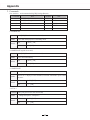
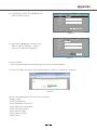
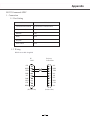
Appendix
RS232 Commands SPEC
1. Connection
1.1 Port Setting
Item
Method
Communication Method
Asynchronous Communication
Bits per seconds
19200
Data bits
8 bits
Parity
None
Stop bits
1
Flow control
None
1.2 Wiring
RS232 cross cable is applied
PC
COM
Projector
Control Port
CD
1
1
N.C.
RXD
2
2
RXD
TXD
DTR
3
3
4
4
TXD
N.C.
SG
5
5
DSR
RTS
6
6
7
7
SG
N.C.
RTS
CTS
8
8
CTS
RING
9
9
N.C.
(D-Sub 9 Pin)
(D-Sub 9 Pin)
59
Appendix
2. Commands
Case sensitive,each command end by[CR](Carriage Returns).
Command
Item
Command
Item
A00
POWER ON
A07
Component
A01
POWER OFF (Quick Power OFF)
A33
Video
A02
POWER OFF
A34
S-Video
A05
VGA1
A36
HDMI
A06
VGA2
2.1 POWER ON
Command “A00”[CR] (Hex: Ox41 0x30 0x30 0x0d)
Details
Return
Power ON when projector is in standby mode
OK
[ACK][CR]
NG
“ ?”[CR]
2.2 POWER OFF (Quick Power Off)
Command “A01”[CR] (Hex:Ox41 0x30 0x31 0x0d)
Details
Return
Power OFF immediately
OK
[ACK][CR]
NG
“ ?”[CR]
2.3 POWER OFF
Command “A02”[CR] (Hex:Ox41 0x30 0x32 0x0d)
Details
Return
"Power off ?" displays for the command, resend the command to power off the
projector
OK
[ACK][CR]
NG
“ ?”[CR]
2.4 VGA 1
Command “A05”[CR] (Hex:Ox41 0x30 0x35 0x0d)
Details
Return
Change the input to "Computer1".
OK
[ACK][CR]
NG
“ ?”[CR]
60
Appendix
2.5 VGA 2
Command “A06”[CR] (Hex:Ox41 0x30 0x36 0x0d)
Details
Change the input to "Computer2".
Return
OK
[ACK][CR]
NG
“ ?”[CR]
2.6 Component
Command “A07”[CR] (Hex:Ox41 0x30 0x37 0x0d)
Details
Change the input to "Component".
Return
OK
[ACK][CR]
NG
“ ?”[CR]
2.7 Video
Command “A33”[CR] (Hex:Ox41 0x33 0x33 0x0d)
Details
Return
Change the input to "Video".
OK
[ACK][CR]
NG
“ ?”[CR]
2.8 S-Video
Command “A34”[CR] (Hex:Ox41 0x33 0x34 0x0d)
Details
Return
Change the input to "S-Video".
OK
[ACK][CR]
NG
“ ?”[CR]
2.9 HDMI
Command “A36”[CR] (Hex:Ox41 0x33 0x36 0x0d)
Details
Return
Change the input to "HDMI".
OK
[ACK][CR]
NG
“ ?”[CR]
NB: [ACK][CR]is the effective return for commands received.
61
Appendix
User manual for network control
Function : this function is for PC’s to remote control projectors through LAN cable.
Preparation:
1. Equipments: PC, projector, cables
2. Connection procedures:
Connect the projector to routers or switches of the LAN by direct or cross cable. If it fails to connect PC and projector
by parallel cable, please switch to cross cable as suggested.
3. After the computer is booted and the projector is plugged in, indicator lights of LAN interface and computer interface
will flash continuously.
Operation procedures:
1. Turn on the projector
2. Obtain network address. DHCP set is displayed as on and obtain network address automatically. If familiar with
network, you can set DHCP as close and obtain network address manually.
3. Enter network settings menu.
(1) Press MENU button of the remote or press
MENU button of the projector first and then
SELECT. The MENU will display. Use arrow
button ▲▼ to select network icon.
(figure 1)
(figure 1)
2) Press SELECT or ► to enter network menu.
(figure 2)
(figure 2)
(3) Use arrow button ▲ ▼ to select network settings and then press SELECT.
(figure 3)
LAN
DHCP
IP Address
Subnet
Gateway
DNS
Network Setting
ON
.
.
.
.
.
.
.
.
set
.
.
.
.
(figure
3)
cancel
62
(figure 3)
Appendix
(4) Press SELECT, choose ON by ▲▼ (figure 4)
and Press SELECT again.
LAN
DHCP
IP Address
Network Setting
ON
Subnet
Gateway
DNS
.
.
.
.
.
.
.
.
.
.
.
.
(figure
3)
set
cancel
(figure 4)
LAN
DHCP
IP Address
Subnet
Gateway
DNS
(5) Select SET by ▲▼(figure 5) and then press
SELECT. Then it will display “waiting...”
on the screen. Wait until it disappears.
Network Setting
ON
.
.
.
.
.
.
.
.
.
.
.
.
set
(figure 5)
4. Check IP address
Enter network menu and select network settings. Press select to check IP address.
5. Enter the IP address (obtained by step 4) into the address bar (figure 6). Format: http:// IP address/.
(figure 6)
6.Set the corresponding items of the projector by the website
Standby: on/off
PCAdj: PC adjustment
Screen: adjustment of screen size
Image: adjustment of image mode
Image Adj: image selection
Input: selection of input
Sound: settings of sound
Setting: others
63
cancel
Appendix
Configuration of terminals
OMPUTER IN 1/COMPUTER IN 2/MONITOR OUT (analog)
Terminal: Analog RGB (D-sub 15-pin)
4
5
10
15
3
9
14
2
8
13
7
12
1
2
3
4
5
6
7
8
1
6
11
Red
Blue (Input/output)
----Grounding (line synchronizing)
Grounding (red)
Grounding (green)
9
10
11
12
13
14
15
----Grounding (field synchronizing)
Grounding
DDC data
Horizontal synchronizing (compound sync.) input/output
Vertical synchronizing
input/output
DDC clock
Grounding (blue)
CONTROL PORT terminal (D-SUB-9-Pin)
1
2
3
4
5
6
7
8
9
(Input/output)
Green (Input/output)
LAN terminal
1
2
3
4
----R X D
T X D
----GND
-----------------
TX +
TX –
RX +
-----
5
6
7
8
87654321
PIN code memorandum
Write down the PIN code in the blank below and keep it,
please contact the repair center.
Factory default PIN code 111*
PIN code lock
Factory default PIN code 111*
Locking startup-animation PIN code
*If this 3-digit number is changed,
the factory default number will be ineffective.
64
----RX –
---------