1
TF 30 GPS Engine
Laipac Technology, Inc.
105 West Beaver Creek Rd. Unit 207 Richmond Hill Ontario L4B 1C6 Canada
Tel: (905) 762-1228 Fax: (905) 763-1737
http://www.laipac.com
Laipac Technology Inc.
Contents
1. Introduction to TF GPS ser ies . . . . . .. . . . . . . . . . . . . . . . . . . . . . . . . . . 8
TF30 GPS Receiver . . . . . . . . . . . . . . . . . . . . . . . . . . . . . . . . . . . . … … … … .8
Quick View on Specifications . . . . . . . . . . . . . . . . . . . . . . . . . . . . . . . . . . . . .8
2. Specifications. . . . . . . . . . . . . . . . . . . . . . . . . . . . . … … … . … … … … .. . 9
TF30 . . . .. . . . . . . . . . . . . . . . . . . . . . . . . . . . . . . . . . . . . . . . . . . . . . . . . . . .9
3. Inter face Descr iption and Options. . . . . . . . . . … … … … … … … … .. .. .11
Phsical Diagram … … … … … … … … … … … … … … … … … … … … … … … .11
Pin Definition of the Digital Interface Connector. . . . . . . . . . . . . … … … . . .12
TF30 . . . . . . . . . . . . . . . . . . . . . . . . . . . . . . . . . . . . . . . . . . . . . . . . . . . . . . . .. 12
Option Descriptions . . . . . . . . . . . . . . . . . . . . . . . . . . . . . . . . . . . . . . . . . .. 14
TricklePower Option… … … … … … … … . . . . . . . . . . . . . . . . . . . . . . . . . . .. .14
RS-232 I/O Option … … … … … … … … … .. . . . . . . . . . . . . . . . . . . . . . . . . 15
4. SiRF Binar y Protocol Specification . … … … … … . . . . . . . . . . . . . . . . . .16
Protocol Layers . . . . . . . . . . . . . . . . . . . . . . . . . . . . . . . . . . . . . . . . . . . . . . . . 16
Transport Message. . . . . . . . . . . . . . . . . . . . . . . . . . . . . . . . . . . . . . . . . . . . . . 16
Transport . . . . . . . . . . . . . . . . . . . . . . . . . . . . . . . . . . . . . . . . . . . . . . . . . . . . . 16
Message Validation . . . . . . . . . . . . . . . . . . . . . . . . . . . . . . . . . . . . . . . . . . . . . 16
Payload Length . . . . . . . . . . . . . . . . . . . . . . . . . . . . . . . . . . . . . . . . . . . . . . . . 16
Payload Data . . . . . . . . . . . . . . . . . . . . . . . . . . . . . . . . . . . . . . . . . . . . . . . . . . .17
Checksum . . . . . . . . . . . . . . . . . . . . . . . . . . . . . . . . . . . . . . . . . . . . . . . . . . . . .17
Input Messages for SiRF Binary Protocol . . . . . . . . . . . . . . . . . . . . . . . . . . . . 17
Initialize Data Source - Message I.D. 128 . . . . . . . . . . . . . . . . . . . . . . . . . . . . 18
Switch To NMEA Protocol - Message I.D. 129 . . . . . . . . . . . . . . . . . . . . . . . .19
Set Almanac – Message I.D. 130 . . . . . . . . . . . . . . . . . . . . . . . . . . . . . . . . . . .21
Software Version – Message I.D. 132 . . . . . . . . . . . . . . . . . . . . . . . . . . . . . . . 21
Set DGPS Source – Message I.D. 133. (For TF10,100/200) . . . . . . . . . . . . . 22
Set Main Serial Port - Message I.D. 134 . . . . . . . . . . . . . . . . . . . . . . . . . . . . .23
Mode Control - Message I.D. 136 . . . . . . . . . . . . . . . . . . . . . . . . . . . . . . . . . .24
-2-
Laipac Technology Inc.
DOP Mask Control - Message I.D. 137 . . . . . . . . . . . . . . . . . . . . . . . . . . . . . .25
DGPS Control - Message I.D. 138 . . . . . . . . . . . . . . . . . . . . . . . . . . . . . . . .
25
Elevation Mask – Message I.D. 139 . . . . . . . . . . . . . . . . . . . . . . . . . . . . . . .
26
Power Mask - Message I.D. 140 . . . . . . . . . . . . . . . . . . . . . . . . . . . . . . . . . .
27
Editing Residual– Message I.D. 141 . . . . . . . . . . . . . . . . . . . . . . . . . . . . . . .
27
Steady State Detection - Message I.D. 142 . . . . . . . . . . . . . . . . . . . . . . . . . . 27
Static Navigation– Message I.D. 143 . . . . . . . . . . . . . . . . . . . . . . . . . . . . . . 27
Poll Clock Status – Message I.D. 144 . . . . . . . . . . . . . . . . . . . . . . . . . . . . . . . .28
Set DGPS Serial Port - Message I.D. 145 . . . . . . . . . . . . . . . . . . . . . . . . . . . 28
Poll Almanac - Message I.D. 146 . . . . . . . . . . . . . . . . . . . . . . . . . . . . . . . . . . .29
Poll Ephemeris - Message I.D. 147 . . . . . . . . . . . . . . . . . . . . . . . . . . . . . . . . . .29
Flash Update - Message I.D. 148. . . . . . . . . . . . . . . . . . . . . . . . . . … … … … … 30
Set Ephemeris - Message I.D. 149. . . . . . . . . . . . . . . . . . . . . . . . . . … … … … .30
Switch Operating Modes - Message I.D. 150 . . . . . . . . . . . . . . . . . . . . . . . . . .31
Set Trickle Power Parameters - Message I.D. 151 . . . . . . . . . . . . . . . . . . . . . .31
Computation of Duty Cycle and On Time . . . . . . . . . . . . . . . . . . . . . . . . . . . ..32
Push-to-Fix . . . . . . . . . . . . . . . . . . . . . . . . . . . . . . . . . . . . . . . . . . . . . . . . . . . ..33
Poll Navigation Parameters - Message I.D. 152 . . . . . . . . . . . . . . . . . . . . . . . ..33
Set UART Configuration – Message I.D.165 … … … ... . . . . . . . . . . . . . . . . . ..34
Low Power Acquisition parameters - Message I.D. 167 . . . . . . . . . . . . . . . . . .36
Output Messages for SiRF Binary Protocol . . . . . . . . . . .. . . . . . . . . . . . . . .
36
Measure Navigation Data Out - Message I.D. 2 . . . . . . . . . . . . . . . . . . . . . .
37
Measured Tracker Data Out - Message I.D. 4 . . . . . . . . . . . . . . . . . . . . . . . . 39
Raw Tracker Data Out - Message I.D. 5 . . . . . . . . . . . . . . . . . . . . . . . . . . . . 41
Software Version String (Response to Poll) - Message I.D. 6 . . . . . . . . . . . .. .41
Response: Clock Status Data - Message I.D. 7 . . . . . . . . . . . . . . . . . . . . . . . 41
50 BPS Data – Message I.D. 8. . . . . . . . . . . . . . . . . . . . . . . . . . . . . . . . . . . . 42
CPU Throughput – Message I.D. 9 . . . . . . . . . . . . . . . . . . . . . . . . . . . . . . . . 43
Command Acknowledgment – Message I.D. 11 . . . . . . . . . . . . . . . . . . . . . .
43
Command NAcknowledgment – Message I.D. 12 . . . . . . . . . . . . . . . . . . . . . ..43
Visible List – Message I.D. 13. . . . . . . . . . . . . . . . . . . . . . . . . . . . . . . . . . . . 44
Almanac Data - Message I.D. 14… … … … … … … … … … . . . . . . . . . . . . . . 45
Ephemeris Data (Response to Poll) – Message I.D. 15 . . . . . . . . . . . . . . . . .
46
OkToSend - Message I.D. 18. . . . . . . . . . . . . . . . . . . . . . . . . . . . . . . . . . . . . ... 46
Navigation Parameters (Response to Poll) – Message I.D. 19 .. . . . . . . . . . ..
-3-
46
Laipac Technology Inc.
Nav. Lib. Measurement Data – Message I.D.28 … … … … … … … … … … … … .47
Nav. Lib. DGPS Data – Message I.D.29 … … … … … … … … … … … … … … … 50
Nav. Lib. SV State Data – Message I.D.30 … … … … … … … … … … … … … … .51
Nav. Lib. Intialization Data – Message I.D.31 ..… … … … … … … … … … … … .52
Development Data – Message I.D. 255 . . . . . . . . . . . . . . . . . . . . . . . . . . . . . 53
Additional Information . . . . . . . . . . . . . . . . . . . . . . . . . . . . . . . . . . . . . . . . . . . 54
TricklePower Operation in DGPS Mode . . . . . . . . . . . . . . . . . . . . . . . . . . . . . 54
GPS Week Reporting
. . . . . . . . . . . . . . . . . . . . . . . . . . . . … 54
NMEA Protocol in TricklePower Mode . . . . . . . . . . . . . . . . . . . . . . . . . . . … 54
5. NMEA Input/Output Messages . . . . . . . … . . . . . . . . . . . . … … … … … . 56
NMEA Output Messages . . . . . . . . . . . . . . . . . . . . . . . . . . . . . . . . . . . . . . . . .56
GGA — Global Positioning System Fixed Data. . . . . . . . . . . . . . . . . . . . . . . .56
GLL— Geographic Position - Latitude/Longitude . . . . . . . . . . . . . . . . . . . . . .57
GSA— GNSS DOP and Active Satellites. . . . . . . . . . . . . . . . . . . . . . . . . . . . . 57
GSV— GNSS Satellites in View . . . . . . . . . . . . . . . . . . . . . . . . . . . . . . . . . . . .58
RMC— Recommended Minimum Specific GNSS Data . . . . . . . . . . . . . . . . ..59
VTG— Course Over Ground and Ground Speed . . . . . . . . . . . . . . . . . . . . . . ..60
SiRF Proprietary NMEA Input Messages . . . . . . . . . . . . . . . . . . . . . . . . . .
60
Transport Message. . . . . . . . . . . . . . . . . . . . . . . . . . . . . . . . . . . . . . . . . . . .
60
SiRF NMEA Input Messages. . . . . . . . . . . . . . . . . . . . . . . . . . . . . . . . . . …
61
SetSerialPort . . . . . . . . . . . . . . . . . . . . . . . . . . . . . . . . . . . . . . . . . . . . . . . . . .. 61
NaviagtionInitialization . . . . . . . . . . . . . . . . . . . . . . . . . . . . . . . . . . . . . . . … ..62
SetDGPSPort . . . . . . . . . . . . . . . . . . . . . . . . . . . . . . . . . . . . . . . . . . . . . . . … 62
Query/Rate Control . . . . . . . . . . . . . . . . . . . . . . . . . . . . . . . . . . . . . . . . . . … 63
LLANaviagtionInitialization . . . . . . . . . . . . . . . . . . . . . . . . . . . . . . . . . . . … 64
Development Data On/Off . . . . . . . . . . . . . . . . . . . . . . . . . . . . . . . . . . . . … .65
-4-
Laipac Technology Inc.
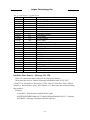
Tables
Table 3-1 Pin List of the 20- pin Digital Interface Connector of
TF30 . . . . . . . . . . . . . . . . . . . . . . . . . . . . . . . . . .
. . . . . . . . . . . . . . . . . . . . . .12
Table 3-2 TricklePower Power Consumption. . . . . . . . . . . . .
Table 4-1 SiRF Messages – Input Message
. . . . . . . . . . . ..15
. . . . . . . . . . . . . . . . . . . . . . . . 18
Table 4-2 Initialize Data Source . . . . . . . . . . . . . . . . . . . .. . . . . . . . . . . . . . . . 19
Table 4-3 Reset Configuration Bitmap . . . . . . . . . . . . . . . . . . . . . . . . . . . .. . . 19
Table 4-4 Switch To NMEA Protocol . . . . . . . . . . . . . . . . . . . . . . . . . . . . . . . .20
Table 4-5 Set Almanac message … … … … .. . . . . . . . . . . . . . . . . . . . . . . . . . . .21
Table 4-6 Software Version. . . . . . . . . . . . . . . . . . . . . . . . . . . . . . . . . . . . . . . . 21
Table 4-7 Set DGPS Source… … … … … … … … … … . . . . . . . . . . . . . . . . . . … 22
Table 4- 8 Set DGPS Source Selections… … … … … … … … … … … . . . . … … 22
Table 4- 9 Set DGPS Source Selections… … … … … … … … … … … … … … … ..22
Table 4- 10 Internal Beacon Serach Settings … … … … … .… … … … .. . . . . … 23
Table 4- 11 Set Main Serial Port … … … .… … … … … … … … … … … . . . . … .23
Table 4-12 Mode Control .. . . . . . . . . . . . . . . . . . . . . . . . . . . . . . . . . . . . . . .. ..24
Table 4- 13 Degraded Mode Byte Value . . . . . . . . . . . . . . . . . . . . . . . . . . . . … 25
Table 4- 14 DOP Mask Control . . . . . . . . . . . . . . . . . . . . . . . . . . . . . . . . . . . … 25
Table 4- 15 DOP Selection . . . . . . . . . . . . . . . . . . . . . . . . . . . . . . . . . . . . . . … .25
Table 4- 16 DGPS Control . . . . . . . . . . . . . . . . . . . . . . . . . . . . . . . . . . . . . . … .26
Table 4- 17 DGPS Selection . . . . . . . . . . . . . . . . . . . . . . . . . . . . . . . . . . . . . … 26
Table 4- 18 Elevation Mask . . . . . . . . . . . . . . . . . . . . . . . . . . . . . . . . . . . . . . … 26
Table 4- 19 Power Mask . . . . . . . . . . . . . . . . . . . . . . . . . . . . . . . . . . . . . . . . … .27
Table 4- 20 Static Navigation … … . . . . . . . . . . . . . . . . . . . . . . . . . . . . . . . . … 27
Table 4- 21 Message ID 143 Description … … … … … ... . . . . . . . . . . . . . . . . … 28
Table 4- 22 Clock Status . . . . . . . . . . . . . . . . . . . . . . . . . . . . . . . . . . . . . . . . … .28
Table 4- 23 Set DGPS Serial Port . . . . . . . . . . . . . . . . . . . . . . . . . . . . . . . . . … .29
Table 4- 24 Almanac . . . . . . . . . . . . . . . . . . . . . . . . . . . . . . . . . . . . . . . . . . . … .29.
Table 4- 25 Ephemeris Message I.D. . . . . . . . . . . . . . . . . . . . . . . . . . . . . . … … .29
Table 4- 26 Flash update … … … … … … … … … … .. . . . . . . . . . . . . . . . . . . . … .30
Table 4- 27 Ephemeris … … … … … … … … … .. . . . . . . . . . . . . . . . . . . . . . . . … .30
-5-
Laipac Technology Inc.
Table 4- 28 Switch Operating Mode I.D.150 . . . . . . . . . . . . . . . . . . . . . . . . . … 31
Table 4- 29 Set Trickle Power Parameters I.D.151 . . . . . . . . . . . . . . . . . . . . . ..32
Table 4- 30 Example of Selections for Trickle Power Mode of Operation . . . ..32
Table 4- 31 Trickle Power Mode Settings . . . . . . . . . . . . . . . . . . . . . . . . . . . . ..32
Table 4- 32 Poll Receiver for Navigation Parameters . . . . . . . . . . . . . . . . . . . ..33
Table 4- 33 Set UART Configuration … … … … … … … … … … … … … … … . . .34
Table 4- 34 Set Message Rate … … … … … … … … … … … ... . . . . . . . . . . . . . . 35
Table 4- 35 Set Low Power Acquisition Parameters … … … … … … … … … . . .36
Table 4- 36 SiRF Messages – Output Message List… … … … … … … ..… … . . .36
Table 4- 37 Measured Navigation Data Out - Binary & ASCII Message Data
Format . . . . . . . . . . . . . . . . . . . . . . . . . . . . . . . . . . . . . . . . . . . . . . . . . . . . . . . . 37
Table 4- 38 Mode 1 . . . . . . . . . . . . . . . . . . . . . . . . . . . . . . . . . . . . . . . . . . . . . . .38
Table 4- 39 Mode 2. . . . . . . . . . . . . . . . . . . . . . . . . . . . . . . . . . . . . . . . . . . . . . ..39
Tab e 4- 40 Measured Tracker Data Out . . . . . . . . . . . . . . . . . . . . . . . . . . . . . ...40
Table 4- 41 TrktoNAVStruct.trk_status Field Definition. . . . . . . . . . . . . . . . . … 40
Table 4- 42 Software Version String. . . . . . . . . . . . . . . . . . . . . . . . . . . . . . . . . … 41
Table 4- 43 Clock Status Data Message. . . . . . . . . . . . . . . . . . . . . . . . . . . . . . … .42
Table 4- 44 50 BPS Data. . . . . . . . . . . . . . . . . . . . . . . . . . . . . . . . . . . . . . . . . . … 42
Table 4- 45 CPU Throughput. . . . . . . . . . . . . . . . . . . . . . . . . . . . . . . . . . . . . . . … 43
Table 4- 46 Command Acknowledgment. . . . . . . . . . . . . . . . . . . . . . . . . . . . . . … 43
Table 4- 47 Command Nacknowledgment. . . . . . . . . . . . . . . . . . . . . . . . . . . . . … 44
Table 4- 48 Visible List. . . . . . . . . . . . . . . . . . . . . . . . . . . . . . . . . . . . . . . . . . . . ..44
Table 4- 49 Almanac Data … … … … … … … … … … … ... . . . . . . . . . . . . . . . . . … 45
Table 4- 50 Ephemeris Data. . . . . . . . . . . . . . . . . . . . . . . . . . . . . . . . . . . . . . . . . ..46
Table 4- 51 Navigation Parameters. . . . . . . . . . . . . . . . . . . . . . . . . . . . . . . . . .. . ..46
Table 4- 52 Measurement Data … … … . . . . . . . . . . . . . . . . . . . . . . . . . . . . . .. . ..48
Table 4- 53 Sync. Flag Fields … … … … … … … … … … … … … .. . . . . . . . . . .. … ..48
Table 4- 54 Detaied Description of the Measurement Data … … … .. . . . . . . .. … ..49
Table 4- 55 Detaied Description of the Measurement Data
(Conti.) … … … … … … … … … … ... . . . . . . . . . . . . . . . . . . . . . . . . . . . . . . . . .. . … 50
Table 4- 56 Measurement Data … … … … … … … .. . . . . . . . . . . . . . . . . . . . . .. … ..50
Table 4- 57 SV State Data … … … … … … ... . . . . . . . . . . . . . . . . . . . . . . . . . .. … … 51
Table 4- 58 Measurement Data … … … … … .. . . . . . . . . . . . . . . . . . . . . . . . . .. … … 52
Table 4- 59 Development Data. . . . . . . . . . . . . . . . . . . . . . . . . . . . . . . . . . . . . . … ..55
Table 4- 60 NMEA Data Rates Under Trickle Power Operation. . . . . . . . . . . . … ..55
-6-
Laipac Technology Inc.
Table 5-1 NMEA-0183 Output Messages .. . . . . . . . . . . . . . . . . . . . .. . . . . . . . .56
Table 5-2 GGA Data Format . . . . . . . . . . . . . . . . . . . . . . . . . . . . . . . . . . .. . . . . . .56
Table 5-3 Position Fix Indicator . . . . . . . . . . . . . . . . . . . . . . . . . . . . . . . . . . . . . . 57
Table 5-4 GLL Data Format . . . . . . . . . . . . . . . . . . . . . . . . . . . . . . . . . . . . . . . . . 57
Table 5-5 GSA Data Format . . . . .. .. . . . . . . . . . . . . . . . . . . . . . . . . . . . . . . . . . . .58
Table 5-6 Mode 1. . . . . . . . . . . . . . . . . . . . . . . . . . . . . . . . . . . . . . . . . . . . . . . . . . 58
Table 5-7 Mode 2. . . . . . . . . . . . . . . . . . . . . . . . . . . . . . . . . . . . . . . . . . . . . . . . . . 58
Table 5-8 GSV Data Format . . . . . . . . . . . . . . . . . . . . . . . . . . . . . . . . . . . . . .. . . .58
Table 5-9 RMC Data Format . . . . . . . . . . . . . . . . . . . . . . . .. . . . . . . . . . . . . . . . ..59
Table 5-10 VTG Data Format . . . . . . . . . . . . . . . . . . . . . . . . .. . . . . . . . . . . . .. . . 60
Table 5-11 Set Serial Port Data Format. . . . . . . . . . . . . . . . . . . . . . . . . . . . . . . . . 61
Table 5-12 Navigation Initialization Data Format. . . . . . . . . . . . . . . . . . . . . . . . . 62
Table 5-13 Reset Configuration. . . . . . . . . . . . . . . . . . . . . . . . . . . . . . . . . . . . . . .62
Table 5-14 Set DGPS Port Data Format . . . . . . . . . . . . . . . . . . . . . . . . . . .. . . . . .63
Table 5-15 Query/Rate Control Data Format (See example 1.) . . . . . . . . . . . .. . .64
Table 5-16 Messages . . . . . . . . . . . . . . . . . . . . . . . . . . . .. . . . . . . . . . . . . . . . . . . 64
Table 5-17 LLA Navigation Initialization Data Format . . . . . .. . .. . . . . . . . . . . .65
Table 5-18 Reset Configuration. . . . . . . . . . . . . . . . . . . . . . . . . . . . . . . . . . . . . . .65
Table 5-19 Development Data On/Off Data Format . . . . . . . . . . . .. . .. . . . . . . . .65
-7-
Laipac Technology Inc.
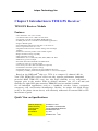
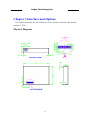
Chapter 1 Introduction to TF30 GPS Receiver
TF30 GPS Receiver Module
Features
‧ Ultra miniature size (30 x 40 mm)
‧ 12 Channel “All-in-vie w ” GPS C/ A and carrier
‧ Inte grated powerful 16-bit ARM7 TDMI CPU core
‧ 8 GPIO pins left for tremendous embedded applications
‧ Suppo rt WAAS signal
‧ Fast Cold/Wa rm/ Hot S tart T TFF time of 45/ 38/8 sec
‧ Fast re acquisition time of 0.1 sec
‧ Degra ded mod e sol ution enables during short blockage
situation
‧ Enhanced sensitivity un der weak sa tellite sign als
‧Single satell ite tra cking capability
‧ Dual multipath rejection
‧ NMEA0183 ver 2.2 GGA, GLL, GSA, GSV, RMC, a nd VTG
‧ SiRF binary protoc ol output
‧On-bo ard Real-time RTCM SC-104 differ en tial
‧ 1 P PS (one pulse per sec ond) signal
‧ Two serial ports with TTL level ( RS-232 optional)
‧ TricklePower function (power saving)
‧ Full shield des ign to withs tand extern al EMI inte rfer ences
‧ Capability of adding user
’s task implementation to curr ent t hroug hput
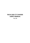
Based on the SiRF starII TM chip set, TF30 is a compact 12-channel “ALL-inView” GPS. TF30 GPS receiver offers not only superior performance (integrated
powerful ARM7 TDMI CPU core), bu t also high reliability at very competitive
compact price in the market. With its delicate miniature size (30 x 40 mm ) and
flexibili ty for eight GPIO pins extension, TF30 GPS receiver module is suitable
for all embedded app lication s such as s handh eld, wireless , leisure, navigation ,
emergency call, and location identification . Besides, its un iqu e full shield design
(refer to the photo sho wn above) will efficiently withstand all external EMI or RFI
inter ference si gnals.
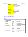
Quick View on Specifications
Channel, Frequency
Position/Velocity
Time Accuracy
Max Speed
Acceleration
Jerk
12 Channel L1 C/A
25 m CEP/0.1 m/s without SA
1 us synchronized to GPS time
515 meters/sec max
4 g., max.
20 meters /sec. 3 max.
-8-
Laipac Technology Inc.
Max Altitude
Time to First Fix
18,000 meters max.
45/38/8/0.1 sec (Cold/Warm/Hot
Start)
0.1 sec (Reacquisition)
Update Rate
Receiver Sensitivity
Map Datum
Input Voltage
Current (Avg.)
Serial Comm.
Protocol Messages
Dimensions
Operating Temp
Storage Temp
1/sec
-175dBW
WGS-84
3.3V DC
50 mA
4800 baud (default)
NMEA 0183 v2.2, SiRF Binary
RTCM SC-104 v2.0 type 1,2,9
Integrated 16-bit ARM7 TDMI
8 GPIO pins
30 x 40 x 7 mm
Full Shield design
-10°C to +70°C
-40°C to +85°C
Chapter 2 Specifications
TF30
1. Electrical Characteristics
1.1 General
Frequency
C/A code
Channels
L1,1575.42MHz
1.023 MHz chip rate
12
1.2 Accuracy
Position
Velocity
Time
25 meters CEP without SA
0.1 meters/second, without SA
1 microsecond synchronized to GPS time
1.3 DGPS Accuracy
Position
Velocity
1 to 5 meters, typical
0.05 meters/second, typical
1.4 Datum
WGS-84
1.5 Acquisition Rate
Reacquisition
Cold start
Warm start
Hot start
0.1 sec., average
45 sec., average
38 sec., average
8 sec., average
1.6 Dynamic Condition
Altitude
Velocity
Acceleration
Jerk
18,000 meters (60,000 Feet) max.
515 meters/sec.(1000 Knots) max.
4 g., max.
20 meters/sec.3 max.
-9-
Laipac Technology Inc.
1.7 Power
Main Power
3.3 Vdc± 10%
~ 150 mA
1.8 External Reset
Supply Current,
continuous
Supply Current,
TricklePower mode
Backup Power
Backup Current
Active low input
1.9 Serial Port
Electrical interface
Two full duplex serial communication(TTL
level or EIA RS-232 level ( optional ))
Design-in binary and NMEA-0183,
Version 2.20 with a baud rate selection
GGA,GLL,GSA,GSV,RMC, and VTG (on
customer request) Default six NMEA
(Baud Rate :4800)
RTCM SC-104, version 2.00, type 1,2 and
9
WAAS Supported
TTL
100 ms
At the pulse positive edge
Aligned to GPS second, ± 1µ sec.
Protocol
NMEA output
DGPS protocol
1.10 Time-1PPS Pulse
Level
Pulse duration
Time reference
Measurements
2. Environmental Characteristics
2.1Temperature
2.2 Physical characteristics
Operating range
Storage range
~ 50 mA
+2.5V to 3.1V
10µA typical
- 10 ℃ to + 70 ℃
- 40 ℃ to + 85 ℃
Dimension
40 X 30 mm, thickness less then 7 mm
Antenna connector
MMCX type
Interface connector
20-pin ( 2X 6) low profile socket, 1mm
8-pin ( 2X 4) JTAG, 1mm ( optional )
3. Antenna
Passive or Active Antenna
4.CPU Throughput
GPS Signal Processor & Integrated 16-bit,50 MHz ARM7TDMI
Software
CPU core & 1M DRAM memory
90% CPU throughput available for user
tasks
5.RF Interference
It is assembled with full shield case design to withstand the
highest possible interference
- 10 -
Laipac Technology Inc.
Chapter 3 Inter face and Options
This chapter describes the pin definitions of the interface connector and flexible
options of TF30.
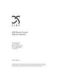
Physical Diagr am
LATERAL VIEW
BOTTOM VIEW
- 11 -
Laipac Technology Inc.
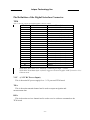
Pin Definition of the Digital Inter face Connector
TF30
Table 3-1 Pin List of the 20- pin Digital Interface Connector of TF30
Pin #
1
2
3
4
5
6
7
8
9
10
11
12
13
14
15
16
17
18
19
20
Name
Description
+3.3V +- 10% DC Power Input
Host Serial Data Output A
Host Serial Data Input A
Aux. Serial Data Output B
Aux. Serial Data Input B (DGPS)
1PPS Time Mark Output
Battery Backup Power Input
General Purpose Input/Output
Reset, Active Low
Reserved
Ground
Internal/External Boot selective
General Purpose Input/Output
General Purpose Input/Output
General Purpose Input/Output
General Purpose Input/Output
General Purpose Input/Output
General Purpose Input/Output
General Purpose Input/Output
Ground
VCC
TXA
RXA
TXB
RXB
TIMEMARK
BAT
GPIOA
RESET
RESERVED
GROUND
BOOTSEL
GPIOB
GPIOC
GPIOD
GPIOE
GPIOF
GPIOG
GPIOH
GROUND
※The Host Serial Data I/O is nominally a CMOS logical high +3.3VDC.
※The Host Serial Data Input A (Pin# 3) suggest to an active high(ex.100KΩserial to + Vcc)
when not used.
VCC
(+3.3V DC Power Input)
This is the main DC power supply for a +3.3V powered TF30 board.
TXA
This is the main transmit channel and is used to output navigation and
measurement data
RXA
This is the main receiver channel and is used to receive software commands to the
TF30 board
- 12 -
Laipac Technology Inc.
TXB
For user’s application (not currently used).
RXB
This is the auxiliary receive channel and is used to input differential corrections to
the TF30 board to enable DGPS navigation.
Timemar k
This pin provides one pulse-per-second output from TF30 board, which is
synchronized to GPS time. This is not available in TricklePower mode.
BAT
This is the battery backup input that powers the SRAM and RTC when main power
is removed. Typical current draw is 10uA.
Without an external backup battery or supercap, TF30 will execute a cold start
after every power on. To achieve the faster start-up offered by a hot or warm start,
a battery backup must be connected. To maximize battery lifetime, the battery voltage
should not exceed the supply voltage and should be between 2.5V and 3.1V.
GPIOA
The pin is connected to the digital interface connector for custom applications
.
RESET
This pin provides an active-low reset input to the TF30 board. It causes the
TF30 board to reset and start searching for satellites. If not utilized, it may be left
open.
GND
GND provides the ground for the TF30 board.
BOOTSEL
Internal/External Boot selective.
GPIOB - GPIOH
These pins are connected to the digital interface connector for custom applications
- 13 -
Laipac Technology Inc.
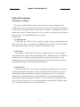
Option Descr iptions
Tr icklePower Option
The design of TF30 includes all the functionality necessary to implement the TricklePower mode of operation. In this mode, the lowest average power dissipation
is achieved by powering down the board (after a position is determined) in such a
manner that when it is turned back on it can re-compute a position fix in the shortest
amount of time. The standard TricklePower operates
in three states:
(1) Tr acking State
In this state, the board is fully powered, tracking satellites and gathering data.
This time in this state is selectable via SiRFdemo demo software from 200-900ms.
After this time the measurements to calculate a position are ready.
(2) CPU State
In this state, the GRF1/LX (RF IC) has been turned off (by the control signal)
removing the clock to the GSP1/LX (Baseband ASIC). Without a clock, the GSP1/LX
is effectively powered down (although the RTC keeps running). The CPU is kept
running to process the GPS data until a position fix is determined and the result has
been transmitted by the serial communication interface.
(3) Tr ickle State
In this state, the CPU is in a low power standby state and the receiver clocks are
off with only the RTC clock active. After a set amount of time, the RTC generates a
NMI signal to wakeup the Hitachi microprocessor and set the receiver back to the
tracking state. The default time for each TricklePower state (and the approximate
current consumed) is shown below in Table 3-3. For example, the TricklePower duty
cycle (20%), the average receiver power dissipation is approximately 165mW (50mA
@ 3.3v) while maintaining a one-second update rate.
- 14 -
Laipac Technology Inc.
Table 3-2 TricklePower Power Consumption
State
Time
+3.3V Current
Tracking
220mS
145mA
CPU
360mS
40mA
Trickle
420mS
0.5mA
Note: Table 3-2 does not include the external antenna power consumption.
RS-232 I/O Option
TF30 allows populating an RS-232 driver. Customers can make request for I/O
of TTL Level (5V) or RS-232 Level (12V).
- 15 -
Laipac Technology Inc.
Chapter 4 SiRF Binar y Protocol Specification
The serial communication protocol is designed to include:
• Reliable transport of messages
• Ease of implementation
• Efficient implementation
• Independence from payload
Protocol Layer s
Tr anspor t Message
1.
Star t
Sequence
Payload
Length Payload
Payload
Message
Checksum
End
Sequence
0xA0 1 ,
0xA2
Two-bytes
(15-bits)
Up to 2 10 –1
(<1023)
Two-bytes
(15-bits)
0xB0,
0xB3
0xYY denotes a hexadecimal byte value. 0xA0 equals 160.
Tr anspor t
The transport layer of the protocol encapsulates a GPS message in two start
characters and two stop characters. The values are chosen to be easily identifiable and
such that they are unlikely to occur frequently in the data. In addition, the transport
layer prefixes the message with a two-byte (15-bit) message length and a two-byte
(15-bit) check sum. The values of the start and stop characters and the choice of a 15bit values for length and check sum are designed such that both message length and
check sum can not alias with either the stop or start code.
Message Validation
The validation layer is of part of the transport, but operates independently. The byte
count refers to the payload byte length. Likewise, the check sum is a sum on the
payload.
Payload Length
The payload length is transmitted high order byte first followed by the low byte.
High Byte
Low Byte
< 0x7F
Any value
- 16 -
Laipac Technology Inc.
Even though the protocol has a maximum length of (2 15 -1) bytes practical
considerations require the SiRF GPS module implementation to limit this value to a
smaller number. Likewise, the SiRF receiving programs (e.g., SiRFdemo) may limit
the actual size to something less than this maximum.
Payload Data
The payload data follows the payload length. It contains the number of bytes
specified by the payload length. The payload data may contain any 8-bit value. Where
multi-byte values are in the payload data neither the alignment nor the byte order are
defined as part of the transport although SiRF payloads will use the big-endian order.
Checksum
The check sum is transmitted high order byte first followed byte the low byte. This
is the so-called big-endian order.
High Byte
Low Byte
< 0x7F
Any value
The check sum is 16-bit checksum of the bytes in the payload data. The following
pseudo code defines the algorithm used.
Let message to be the array of bytes to be sent by the transport.
Let msgLen be the number of bytes in the message array to be transmitted.
Index = first
checkSum = 0
while index < msgLen
checkSum = checkSum + message[index]
checkSum = checkSum AND (2 10 -1).
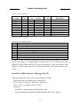
Input Messages for SiRF Binar y Protocol
Note – All input messages are sent in BINARY format.
Table 4-1 lists the message list for the SiRF input messages.
- 17 -
Laipac Technology Inc.
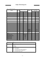
Table 4- 1 SiRF Messages - Input Message List
Hex
0 x 80
0 x 81
0 x 82
0 x 84
0 x 85
0 x 86
0 x 88
0 x 89
0 x 8A
0 x 8B
0 x 8C
0 x 8D
0 x 8E
0 x 8F
0 x 90
0 x 91
0 x 92
0 x 93
0 x 94
0 x 95
0 x 96
0 x 97
0 x 98
0 x A5
0 x A6
0 x A7
ASCII
128
129
130
132
133
134
136
137
138
139
140
141
142
143
144
145
146
147
148
149
150
151
152
165
166
167
Name
Initialize Data Source
Switch to NMEA Protocol
Set Almanac (upload)
Software Version (Poll)
Set DGPS Source Control
Set Main Serial Port
Mode Control
DOP Mask Control
DGPS Mode
Elevation Mask
Power Mask
Editing Residual (Not implemented)
Steady-State Detection (Not implemented)
Static Navigation
Poll Clock Status
Set DGPS Serial Port
Poll Almanac
Poll Ephemeris
Flash Update
Set Ephemeris (upload)
Switch Operating Mode
Set Trickle Power Parameters
Poll Navigation Parameters
Set UART Configuration
Set Message Rate
Low Power Acquisition Parameters
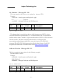
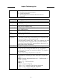
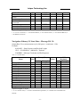
Initialize Data Source - Message I.D. 128
Table 4-2 contains the input values for the following example:
Warm start the receiver with the following initialization data: ECEF XYZ
(-2686727 m, -4304282 m, 3851642 m), Clock Offset (75,000 Hz), Time of Week
(86,400 s), Week Number (924), and Channels (12). Raw track data enabled, Debug
data enabled.
Example:
A0A20019— Start Sequence and Payload Length
80FFD700F9FFBE5266003AC57A000124F80083D600039C0C33— Payload
0A91B0B3— Message Checksum and End Sequence
- 18 -
Laipac Technology Inc.
Table 4- 2 Initialize Data Source
Binar y (Hex)
Scale
Example
Name
Bytes
Message ID
1
80
ECEF X
4
FFD700F
ECEF Y
4
FFBE5266
ECEF Z
4
003AC57A
Clock Offset
4
000124F8
Time of Week
4
*100
0083D600
Week Number
2
039C
Channels
1
0C
Reset Config.
1
33
Payload Length: 25 bytes
Units
Descr iption
ASCII 128
meters
meters
meters
Hz
seconds
Range 1-12
See table Table 4-3
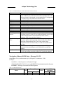
Table 4- 3 Reset Configuration Bitmap
Bit
Descr iption
0
Data valid flag— set warm/hot start
1
Clear ephemeris— set warm start
2
Clear memory— set cold start
3
Factory Reset
4
Enable raw track data (YES=1, NO=0)
5
Enable debug data for SiRF binary protocol (YES=1, NO=0)
6
Enable debug data for NMEA protocol (YES=1, NO=0)
7
Reserved (must be 0)
Note – If Nav Lib data is ENABLED then the resulting messages are enabled.
Clock Status (MID 7), 50 BPS (MID 8), Raw DGPS (17), NL Measurement Data
(MID 28), DGPS Data (MID 29), SV State Data (MID 30), and NL Initialize Data
(MID 31). All messages are sent at 1 Hz and the baud rate will be automatically set to
57600.
Switch To NMEA Protocol - Message I.D. 129
Table 4-4 contains the input values for the following example:
Request the following NMEA data at 4800 baud:
GGA – ON at 1 sec, GLL – OFF, GSA - ON at 5 sec,
GSV – ON at 5 sec, RMC-OFF, VTG-OFF
Example:
A0A20018— Start Sequence and Payload Length
8102010100010501050100010001000100010001000112C0— Payload
- 19 -
Laipac Technology Inc.
016AB0B3— Message Checksum and End Sequence
Table 4- 4 Switch To NMEA Protocol
Binar y(Hex)
Name
Bytes Scale Example
Message ID
1
81
Mode
1
02
1
GGA Message
1
01
Checksum 2
1
01
GLL Message
1
00
Checksum
1
01
GSA Message
1
05
Checksum
1
01
GSV Message
1
05
Checksum
1
01
RMC Message
1
00
Checksum:
1
01
VTG Message
1
00
Checksum
1
01
Unused Field
1
00
Unused Field
1
01
Unused Field
1
00
Unused Field
1
01
Unused Field
1
00
Unused Field
1
01
Unused Field
1
00
Unused Field
1
01
Baud Rate
2
12C0
Units
Descr iption
ASCII 129
1/s
See Chapeter 5 for format.
1/s
Se Chapeter 5 for format.
1/s
See Chapeter 5 for format.
1/s
See Chapeter 5 for format.
1/s
See Chapeter 5 for format.
1/s
See Chapeter 5 for format.
Recommended value.
Recommended value.
Recommended value.
Recommended value.
Recommended value.
Recommended value.
Recommended value.
Recommended value.
38400,
19200,9600,4800,2400
Payload Length: 24 bytes
1. A value of 0x00 implies NOT to send message, otherwise data is sent at 1 message every X seconds
requested (i.e., to request a message to be sent every 5 seconds, request the message using a value of
0x05.) Maximum rate is 1/255s.
2. A value of 0x00 implies the checksum NOT transmitted with the message (not recommended). A
value of 0x01 will have a checksum calculated and transmitted as part of the message (recommended).
Note – In Trickle Power mode, update rate is specified by the user. When you
switch to NMEA protocol, message update rate is also required. The resulting update
rate is the product of the Trickle Power Update rate AND the NMEA update rate (i.e.
Trickle Power update rate = 2 seconds, NMEA update rate = 5 seconds, resulting
update rate is every 10 seconds, (2 X 5 = 10)).
- 20 -
Laipac Technology Inc.
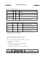
Set Almanac – Message I.D. 130
This com mand en ables the u ser to up load an alman ac TF30
Example:
A0A20380 – Start Sequence and Payload Length
82xx… … … … … … … . – Payload
xxxxB0B3 – Message Checksum and End Sequence
Table 4-5 Set Almanac message
Binar y (Hex)
Scale
Name
Bytes
Message ID
1
Almanac
896
Payload Length: 897 bytes
Example
Units
82
00
Descr iption
ACSII 130
Reserved
The almanac data is stored in the code as a 448 element array of INT16 values.
These 448 elements are partitioned as 32 x 14 elements where the 32 represents the
satellite number minus 1 and the 14 represents the number of INT16 values associated
with this satellite. The data is actually packed and the exact format of this
representation and packing method can be extracted from the ICD-GPS-2000
document. The ICD-GPS-2000 document describes the data format of each GPS
navigation sub-frame and is available on the web at http://www.arinc.com/gps
Software Ver sion – Message I.D. 132
Table 4-6 contains the input values for the following example:
Poll the software version
Example:
A0A20002— Start Sequence and Payload Length
8400— Payload
0084B0B3— Message Checksum and End Sequence
Table 4- 6 Software Version
Binar y (Hex)
Scale
Name
Bytes
Message ID
1
TBD
1
Payload Length: 2 bytes
Example
Units
84
00
- 21 -
Descr iption
ACSII 132
Not used
Laipac Technology Inc.
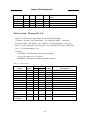
Set DGPS Source – Message I.D. 133
This command allows the user to select the source for DGPS Correction s. Options
available are:
External RTCM Data ( any ser ial port)
WAAS (subject to WAAS satellite a vailab ility)
Internal D GPS beacon receiver
Example 1: Set the D GPS sour ce to E xte rnal RTCM Data
A0A200007— Start Sequ ence and P a yload Length
8502000000000 —0 Payload
0087B0 B3— Checksum and End Seq uen ce
Table 4-7 Set DGPS Source
Name
Message ID
DGPS Sour ce
Bytes
1
1
Binar y (Hex)
Scale Example Units
85
02
Internal Beacon 4
Freq uen cy
Internal Beacon 1
Bit Rate
Payload Length: 7 bytes
00000000
Hz
00
BPS
Descr iption
de cimal 133
See Table 4-9– DGPS
Sou rce Selection s
Internal Beacon Se arch
Sett ings
Internal Beacon Se arch
Sett ings
Example2: Set the D GPS sour ce to Int ernal DGPS Beacon R ece (Current ly
TF30 is not supported)
Search Frequency 310000, Bit Rate 200
A0A200007— Start Sequence and Payload Length
85030004BAF0C802— Payload
02FEB0B3— Checksum and End Sequence
Table 4 - 8 DGPS Source Selection (Example 2)
Name
Message I.D.
DGPS Source
Bytes Scale Hex
1
85
1
03
Internal Beacon 4
Frequency
Internal Beacon 1
Bit Rate
0004BAF0
C8
Units Decimal Descr iption
133
Message Identification.
3
See Table 4-9 DGPS
Source Selections.
HZ
310000 See Table 4-9 Internal
Beacon Search Settings .
BPS 200
See Table 4-10 Internal
Beacon Search Settings.
- 22 -
Laipac Technology Inc.
Table 4- 9 Set DGPS Source Selections
DGPS
None
Hex Decimal Descr iption
0
0
DGPS corrections will not be used (even if
available).
WAAS
1
1
Uses WAAS Satellite (subject to availability).
External RTCM 2
2
External RTCM input source (i.e., Coast Guard
Data
Beacon).
Internal DGPS 3
3
Internal DGPS beacon receiver.
Beacon Receiver
User software
4
4
Corrections provided using a interface module
routine in a customer user application
Table 4- 10 Internal Beacon Search Settings
Search Type
Auto Scan
Frequency 1 Bit Rate 2
0
0
Full Frequency 0
Scan
Full Bit Rate
None Zero
Scan
Specific Search None Zero
Scan
None Zero
0
None Zero
Descr iption
Auto scanning of all frequencies and
bit rates are performed.
Auto scanning of all frequencies and
specified bit rate are performed.
Auto scanning of all bit rates and
specified frequency are performed.
Only the specified frequency and bit
rate search are performed.
1. Frequency Range is 283500 to 325000 Hz.
2.Bit Rate selection is 25, 50, 100 and 200 BPS.
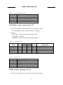
Set Main Ser ial Por t - Message I.D. 134
Table 4-11 contains the input values for the following example:
Set Main Serial port to 9600,n,8,1.
Example:
A0A20009— Start Sequence and Payload Length
860000258008010000— Payload
0134B0B3— Message Checksum and End Sequence
Table 4- 11 Set Main Serial Port
Binar y (Hex)
Example
Name
Bytes Scale
Message ID
1
86
Units
- 23 -
Descr iption
Decimal 134
Laipac Technology Inc.
Baud
4
00002580
Data Bits
1
Stop Bit
1
Parity
1
Pad
1
Payload Length: 9 bytes
38400,19200,9600,4800,2400,
1200
8,7
0,1
None=0, Odd=1, Even=2
Reserved
08
01
00
00
Mode Control - Message I.D. 136
Table 4-12 contains the input values for the following example:
3D Mode = Always, Alt Constraining = Yes, Degraded Mode = clock then
direction, TBD=1, DR Mode = Yes, Altitude = 0, Alt Hold Mode = Auto, Alt
Source =Last Computed, Coast Time Out = 20, Degraded Time Out=5, DR Time
Out = 2, Track Smoothing = Yes
Example:
A0A2000E— Start Sequence and Payload Length
88010101010100000002140501— Payload
00A9B0B3— Message Checksum and End Sequence
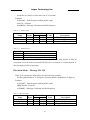
Table 4-12 Mode Control
Binar y (Hex)
Name
Bytes
Message ID
1
3D Mode
1
Alt Constraint
1
Degraded Mode
1
TBD
1
DR Mode
1
Altitude
2
Alt Hold Mode
1
Alt Source
1
Coast Time Out
1
1
Degraded Time
Out
DR Time Out
1
Track
1
Smoothing
Payload Length: 14 bytes
Scale
Units
88
01
01
01
01
01
0000 meters
00
02
14 Seconds
05 Seconds
Example
01
01
Seconds
- 24 -
Descr iption
ASCII 136
1 (always true=1)
YES=1, NO=0
See Table 4-13
Reserved
YES=1, NO=0
range -1,000 to 10,000
Auto=0, Always=1,Disable=2
Last Computed=0,Fixed to=1
0 to 120
0 to 120
0 to 120
YES=1, NO=0
Laipac Technology Inc.
Table 4- 13 Degraded Mode Byte Value
Byte Value
0
1
2
3
4
Descr iption
Use Direction then Clock Hold
Use Clock then Direction Hold
Direction (Curb) Hold Only
Clock (Time) Hold Only
Disable Degraded Modes
DOP Mask Control - Message I.D. 137
Table 4-14 contains the input values for the following example:
Auto Pdop/Hdop, Gdop =8 (default), Pdop=8, Hdop=8
Example:
A0A20005— Start Sequence and Payload Length
8900080808— Payload
00A1B0B3— Message Checksum and End Sequence
Table 4- 14 DOP Mask Control
Binar y (Hex)
Name
Bytes Scale Example
Message ID
1
89
DOP Selection
1
00
GDOP Value
1
08
PDOP Value
1
08
HDOP Value
1
08
Payload Length: 5 bytes
Units
Descr iption
ASCII 137
See Table 4-15
Range 1 to 50
Range 1 to 50
Range 1 to 50
Table 4- 15 DOP Selection
Byte Value
0
1
2
3
4
Descr iption
Auto PDOP/HDOP
PDOP
HDOP
GDOP
Do Not Use
DGPS Control - Message I.D. 138
Table 4-16 contains the input values for the following example:
- 25 -
Laipac Technology Inc.
Set DGPS to exclusive with a time out of 30 seconds.
Example:
A0A20003— Start Sequence and Payload Length
8A011E— Payload
00A9B0B3— Message Checksum and End Sequence
Table 4- 16 DGPS Control
Binar y (Hex)
Name
Bytes
Message ID
1
DGPS Selection
1
DGPS Time Out
1
Payload Length: 3 bytes
Scale
Example
8A
01
1E
Units
Descr iption
ASCII 138
See Table 4-17
seconds Range 0 to 255
Table 4- 17 DGPS Selection
Byte Value
Descr iption
0
Auto
1
Exclusive
2
Never Use
Note – Configuration of the DGPS mode using MID 138 only applies to RTCM
corrections received from an external RTCM source or internal or external beacon. It
does not apply to WAAS operation.
Elevation Mask – Message I.D. 139
Table 4-18 contains the input values for the following example:
Set Navigation Mask to 15.5 degrees (Tracking Mask is defaulted to 5 degrees).
Example:
A0A20005— Start Sequence and Payload Length
8B0032009B— Payload
0158B0B3— Message Checksum and End Sequence
Table 4- 18 Elevation Mask
Name
Message ID
Tracking Mask
Navigation Mask
Binar y (Hex)
Bytes Scale Example
1
8B
2
*10
0032
2
*10
009B
- 26 -
Units
degrees
degrees
Descr iption
ASCII 139
Not currently used
Range -20.0 to 90.0
Laipac Technology Inc.
Payload Length: 5 bytes
Power Mask - Message I.D. 140
Table 4-19 con tains the inpu t value s for the following example:
Navigation mask to 33 dB Hz (tracki ng default value of 28)
Example:
A0A2000 3— Start Sequ ence and P a yload Length
8C1C21— Payload
00C9B0B3— Message Ch ecksum and End Sequ ence
Table 4- 19 Power Mask
Binar y (Hex)
Name
Bytes
Message ID
1
Track ing Mask
1
Navigation Mask
1
Payload Length: 3 bytes
Scale
Example
8C
1C
21
Units
dBHz
dBHz
Descr iption
ASCII 140
Not cu rrent ly implem ented
Range 20 to 50
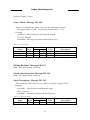
Editing Residual– Message I.D. 141
Note – Not implemented current ly.
Steady State Detection -Message I.D. 142
Note – Not implemented current ly.
Static Navigation– Message I.D. 143
This command allows the user to enable or disable navigatio TF30.
Example:
A0A20002 – Start Sequence and Payload Length
8F01 – Payload
xxxxB0B3 – Message Checksum and End Sequence
Table 4- 20 Static Navigation
Binar y (Hex)
Name
Message ID
Bytes
1
Scale
Example
8F
- 27 -
Units
Descr iption
ASCII 143
Laipac Technology Inc.
Static Navigation
1
Flag
Payload Length: 2 bytes
01
degrees
ASCII 1
Table 4- 21 Message ID 143 Description
Name
Message ID
Static Navigation Flag
Descr iption
Message ID number
Valid values:
1: enable static navigation
0: disable static navigation
Poll Clock Status – Message I.D. 144
Table 4-22 contains the input values for the following example:
Poll the clock status.
Example:
A0A20002— Start Sequence and Payload Length
9000— Payload
0090B0B3— Message Checksum and End Sequence
Table 4- 22 Clock Status
Binar y (Hex)
Name
Bytes
Message ID
1
TBD
1
Payload Length: 2 bytes
Scale
Example
Units
90
00
Descr iption
ACSII 144
Not used
Set DGPS Ser ial Por t - Message I.D. 145
Table 4-23 contains the input values for the following example:
Set DGPS Serial port to 9600,n,8,1.
Example:
A0A20009— Start Sequence and Payload Length
910000258008010000— Payload
013FB0B3— Message Checksum and End Sequence
- 28 -
Laipac Technology Inc.
Tab e 4- 23 Set DGPS Serial Port
Binar y (Hex)
Name
Bytes Scale
Message ID 1
Baud
4
Data Bits
1
Stop Bit
1
Parity
1
Pad
1
Payload Length: 9 bytes
Example
Units
91
00002580
08
01
00
00
Descr iption
ASCII 145
38400,19200,9600,4800,2400,120
8,7
0,1
Non e= 0, Odd= 1, Even= 2
Reserved
0
Note – Sett ing the DGPS se rial port usi ng MID 145 will e ffect Com B on ly regardl ess
of the port being used to com mun icTF 30.
Poll Almanac - Message I.D. 146
Table 4-24 contains the input values for the following example:
Poll for the Almanac.
Example:
A0A20002— Start Sequence and Payload Length
9200— Payload
0092B0B3— Message Checksum and End Sequence
Table 4- 24 Almanac
Binar y (Hex)
Scale
Example
Name
Bytes
Message ID
1
92
TBD
1
00
Payload Length: 2 bytes
Units
Descr iption
ASCII 146
Reserved
Poll Ephemer is - Message I.D. 147
Table 4-25 contains the input values for the following example:
Poll for Ephemeris Data for all satellites.
Example:
A0A20003— Start Sequence and Payload Length
930000— Payload
0092B0B3— Message Checksum and End Sequence
- 29 -
Laipac Technology Inc.
Table 4- 25 Ephemeris Message I.D.
Binar y (Hex)
Name
Bytes
Message ID
1
Sv I.D.1
1
TBD
1
Payload Length: 3 bytes
Scale
Example
Units
93
00
00
Descr iption
ASCII 147
Range 0 to 32
Not used
1. A value of 0 requests all available ephemeris records, otherwise the ephemeris of the Sv I.D. is
requested.
Flash Update - Message I.D. 148
This command allows the user to command the Evaluation Receiver to go into
internal boot mode without setting the boot switch. Internal boot mode allows the user
to re-flash the embedded code in the receiver.
Note – It is highly recommended that all hardware designs should still provide access
to the boot pin in the event of a failed flash upload.
Example:
A0A20001 – Start Sequence and Payload Length
94 – Payload
0094B0B3 – Message Checksum and End Sequence
Table 4- 26 Flash update
Binar y (Hex)
Scale
Example
Name
Bytes
Message ID
1
94
Payload Length: 1 bytes
Units
Descr iption
ASCII 148
Set Ephemer is – Message I.D. 149
This command enables the user to upload an ephemeris file to the Evaluation
Receiver.
Example:
A0A2005B – Start Sequence and Payload Length
95… … … … … … … . – Payload
xxxxB0B3 – Message Checksum and End Sequence
Table 4-27 Ephemeris
Binar y (Hex)
Name
Message ID
Ephemeris
Bytes
1
90
Scale
Example
Units
95
00
Descr iption
ASCII 149
Reserved
- 30 -
Laipac Technology Inc.
data
Payload Length: 91 bytes
The ephemeris data for each satellite is stored as a two dimensional array of [3][15]
UNIT16 elements. The 3 represents three separate sub-frames. The data is actually
packed and the exact format of this representation and packing method can be
extracted from the ICD-GPS-2000 document. The ICD-GPS-2000 document
describes the data format of each GPS navigation sub-frame and is available on the
web at http://www.arinc.com/gps.
Switch Oper ating Modes - Message I.D. 150
Table 4-28 contains the input values for the following example:
Sets the receiver to track a single satellite on all channels.
Example:
A0A20007— Start Sequence and Payload Length
961E510006001E— Payload
0129B0B3— Message Checksum and End Sequence
Table 4- 28 Switch Operating Mode I.D.150
Binar y (Hex)
Name
Bytes
Message ID
1
Mode
2
Scale
SvID
2
Period
2
Payload Length: 7 bytes
Example
96
1E51
0006
001E
Units
Descr iption
ASCII 150
0=normal,
1E51=Testmode1,
1E52=Testmode2,
1E53= not supported
Satellite to Track
seconds Duration of Track
Set Tr ickle Power Par ameter s - Message I.D. 151
Table 4-29 contains the input values for the following example:
Sets the receiver into low power Modes.
Example: Set receiver into Trickle Power at 1 hz update and 200 ms On Time.
A0A20009— Start Sequence and Payload Length
97000000C8000000C8— Payload
0227B0B3— Message Checksum and End Sequence
- 31 -
Laipac Technology Inc.
Table 4- 29 Set Trickle Power Parameters I.D.151
Binar y (Hex)
Name
Message ID
Push To Fix Mode
Duty Cycle
Milli Seconds On
Time
Scale
Example
Bytes
1
2
2
*10
97
0000
00C8
4
Units
%
000000C8 msec
Descr iption
ASCII 151
ON = 1, OFF = 0
% Time ON. A duty
cycle of 1000 (100%)
means
continuous
operation
range 200 - 500 ms
Payload Length: 9 bytes
Note- On time of 700, 800, 900 msec are invalid if update rate of 1 second is selected.
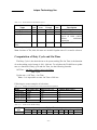
Computation of Duty Cycle and On Time
The Duty Cycle is the desired time to be spent tracking.The On Time is the duration
of each tracking period (range is 200 - 900 ms). To calculate the TricklePower update
rate as a function of Duty cycle and On Time, use the following formula:
Off Time = On Time - (Duty Cycle * On Time)
Duty Cycle
Update rate = Off Time + On Time
Note – It is impossible to enter On Time of 900 ms.
Following are some examples of selections:
Table 4- 30 Example of Selections for Trickle Power Mode of Operation
Mode
Continuous
Trickle Power
Trickle Power
Trickle Power
Trickle Power
On Time (ms)
1000
200
200
300
500
Duty Cycle (% )
100
20
10
10
5
Update Rate(1/Hz)
1
1
2
3
10
Table 4- 31 Trickle Power Mode Settings
On Time
(ms)
200
1
Y1
2
Y
3
Y
4
Y
Update Rate (sec)
5
6
7
Y
Y
Y
- 32 -
8
Y
9
Y
10
Y
Laipac Technology Inc.
300
400
500
600
700
800
900
Y
Y
Y
Y
N
N
N
Y
Y
Y
Y
Y
Y
Y
Y
Y
Y
Y
Y
Y
Y
Y
Y
Y
Y
Y
Y
Y
Y
Y
Y
Y
Y
Y
Y
Y
Y
Y
Y
Y
Y
Y
Y
Y
Y
Y
Y
Y
Y
Y
Y
Y
Y
Y
Y
Y
Y
Y
Y
Y
Y
Y
Y
Y
Y
Y
Y
Y
Y
Y
1.Y = Yes (Mode supported)
2. N = No (Mode NOT supported)
Push-to-Fix
In this mode the receiver will turn on every 30 minutes to perform a system update
consisting of a RTC calibration and satellite ephemeris data collection if required (i.e.,
a new satellite has become visible) as well as all software tasks to support SnapStart
in the event of an NMI. Ephemeris collection time in general takes 18 to 30 seconds.
If ephemeris data is not required then the system will re-calibrate and shut down. In
either case, the amount of time the receiver remains off will be in proportion to how
long it stayed on:
Off period = On Period*(1-Duty Cycle)
Duty Cycle
The off period has a possible range between 10 and 7200 seconds. The default is
1800 seconds.
Poll Navigation Par ameter s - Message I.D. 152
Table 4-32 contains the input values for the following example:
Example: Poll receiver for current navigation parameters.
A0A20002— Start Sequence and Payload Length
9800— Payload
0098B0B3— Message Checksum and End Sequence
Table 4-32 Poll Receiver for Navigation Parameters
Binar y (Hex)
Name
Bytes
Message ID
1
Reserved
1
Payload Length: 2 bytes
Scale
Example
98
00
- 33 -
Units
Descr iption
ASCII 152
Reserved
Laipac Technology Inc.
Set UART Configur ation - Message I.D. 165
Table 4-33 contains the input values for the following example:
Example: Set port 0 to NMEA with 9600 baud, 8 data bits, 1 stop bit, no parity.
Set port 1 to SiRF binary with 57600 baud, 8 data bits, 1 stop bit, no parity. Do
not configure ports 2 and 3.
Example:
A0A20031— Start Sequence and Payload Length
A50001010000258008010000000100000000E1000801000000FF0505000000000000000000FF05050
00000000000000000—
Payload
0452B0B3— Message Checksum and End Sequence
Table 4- 33 Set UART Configuration
Name
Bytes
Message ID
Port
In Protocol 1
Out Protocol
Baud Rate 2
Data Bits 3
Stop Bits 4
Parity 5
Reserved
Reserved
Port
In Protocol
Out Protocol
Baud Rate
Data Bits
Stop Bits
Parity
Reserved
Reserved
Port
In Protocol
Out Protocol
Baud Rate
Data Bits
Stop Bits
Parity
Reserved
1
1
1
1
4
1
1
1
1
1
1
1
1
4
1
1
1
1
1
1
1
1
4
1
1
1
1
Binar y (Hex)
Units
Scale Example
A5
00
01
01
00002580
08
01
00
00
00
01
00
00
0000E100
08
01
00
00
00
FF
05
05
00000000
00
00
00
00
- 34 -
Descr iption
ASCII 165
For UART 0
For UART 0
For UART 0 (Set to in protocol)
For UART 0
For UART 0
For UART 0
For UART 0
For UART 0
For UART 0
For UART 1
For UART 1
For UART 1
For UART 1
For UART 1
For UART 1
For UART 1
For UART 1
For UART 1
For UART 2
For UART 2
For UART 2
For UART 2
For UART 2
For UART 2
For UART 2
For UART 2
Laipac Technology Inc.
Reserved
1
Port
1
In Protocol
1
Out Protocol
1
Baud Rate
4
Data Bits
1
Stop Bits
1
Parity
1
Reserved
1
Reserved
1
Payload Length: 49 bytes
00
FF
05
05
00000000
00
00
00
00
00
For UART 2
For UART 3
For UART 3
For UART 3
For UART 3
For UART 3
For UART 3
For UART 3
For UART 3
For UART 3
1. 0 = SiRF Binary, 1 = NMEA, 2 = ASCII, 3 = RTCM, 4 = User1, 5 = No Protocol.
2. Valid values are 1200, 2400, 4800, 9600, 19200, 38400, and 57600.
3. Valid values are 7 and 8.
4. Valid values are 1 and 2.
5. 0 = None, 1 = Odd, 2 = Even.
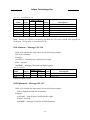
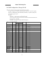
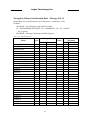
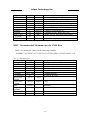
Set Message Rate - Message I.D. 166
Table 4-34 contains the input values for the following example:
Set message ID 2 to output every 5 seconds starting immediately.
Example:
A0A20008— Start Sequence and Payload Length
A601020500000000— Payload
00AEB0B3— Message Checksum and End Sequence
Table 4-34 Set Message Rate
Name
Bytes
Message ID
1
1
1
Send Now
MID to be set 1
Update Rate
1
Reserved
1
Reserved
1
Reserved
1
Reserved
1
Payload Length: 8 bytes
Binar y (Hex)
Scale Example
A6
01
02
05
00
00
00
00
Units
ASCII 166
Poll message
sec
1. 0 = No, 1 = Yes, if no update rate the message will be polled.
- 35 -
Descr iption
Range = 1 - 30
Not used
Not used
Not used
Not used
Laipac Technology Inc.
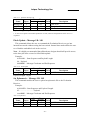
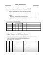
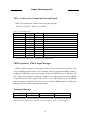
Low Power Acquisition Par ameter s - Message I.D. 167
Table 4-35 contains the input values for the following example:
Set maximum off and search times for re-acquisition while receiver is in
low power.
Example:
A0A20019— Start Sequence and Payload Length
A7000075300001D4C000000000000000000000000000000000— Payload
02E1B0B3— Message Checksum and End Sequence
Table 4- 35 Set Low Power Acquisition Parameters
Name
Bytes
Message ID
Max Off Time
Max Search
Time
Push-To-Fix
period
1
4
4
4
Binar y (Hex)
Scale Example
A7
00007530
0001D4C
0
0000003C
Units
Descr iption
ms
ms
ASCII 167
Maximum time for sleep mode
Max. satellite search time
sec
Push-To-Fix cycle period
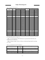
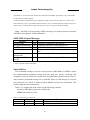
Output Messages for SiRF Binar y Protocol
Note – All output messages are received in BINARY format. SiRFdemo interprets
the binary data and saves it to the log file in ASCII format.
Table 4-36 lists the message list for the SiRF output messages.
Table 4- 36 SiRF Messages - Output Message List
Hex ASCII
0 x 02
2
0 x 03
3
0 x 04
4
0 x 05
5
0 x 06
6
0 x 07
7
0 x 08
8
0 x 09
9
0 x 0A
10
0 x 0B
11
Name
Measured Navigation Data
True Tracker Data
Measured Tracking Data
Raw Tra ck Data
SW Version
Clock Status
50 BPS Subframe Data
Throughput
Error ID
Command Acknowledgment
- 36 -
Descr iption
Position, velocity, and time
Not Implemented
Satellite and C/No information
TF30 not supported
Receiver software
Current clock status
Standard ICD format
Navigation complete data
Error coding for message failure
Successful request
Laipac Technology Inc.
0 x 0C
0 x 0D
0 x 0E
0 x 0F
0 x 10
0 x 11
0 x 12
0 x 13
0 x 14
0 x 1C
0 x 1D
0 x 1E
0 x 1F
0 x FF
12
13
14
15
16
17
18
19
20
28
29
30
31
255
Command Nacknowledgment
Visible List
Almanac Data
Ephemeris Data
Test Mode 1
Differential Corrections
OkToSend
Navigation Parameters
Test Mode 2
Nav. Lib. Measurement Data
Nav. Lib. DGPS Data
Nav. Lib. SV State Data
Nav. Lib. Initialization Data
Development Data
Unsuccessful request
Auto Output
Response to Poll
Response to Poll
For use with SiRFtest 1 (Test mode 1)
Received from DGPS broadcast
CPU ON / OFF (Trickle Power)
Response to Poll
Additional test data (Test mode 2)
Measurement Data
Differential GPS Data
Satellite State Data
Initialization Data
Various status messages
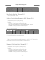
1. SiRFtest is product testing software tool.
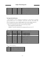
Measure Navigation Data Out - Message I.D. 2
Output Rate: 1 Hz
Table 4-37 lists the binary and ASCII message data format for the measured
navigation data
Example:
A0A20029— Start Sequence and Payload Length
02FFD6F78CFFBE536E003AC00400030104A00036B039780E3
0612190E160F04000000000000— Payload
09BBB0B3— Message Checksum and End Sequence.
Table 4- 37 Measured Navigation Data Out - Binary & ASCII Message Data Format
Name
Message ID
X-position
Y-position
Z-position
X-velocity
Y-velocity
Z-velocity
Mode 1
DOP 2
Mode 2
Bytes
1
4
4
4
2
2
2
1
1
1
Binar y (Hex)
Scale
Example
02
FFD6F78C
FFBE536E
003AC004
*8
00
*8
03
*8
01
04
*5
A
00
- 37 -
Units
m
m
m
m/s
m/s
m/s
Bitmap 1
Bitmap 3
ASCII (Decimal)
Scale
Example
2
-2689140
-4304018
3850244
0
Vx÷ 8
0.375
Vy÷ 8
0.125
Vz÷ 8
4
2.0
÷ 5
0
Laipac Technology Inc.
GPS Week
2
GPS TOW
4
*100
SVs in Fix
1
CH 1
1
CH 2
1
CH 3
1
CH 4
1
CH 5
1
CH 6
1
CH 7
1
CH 8
1
CH 9
1
CH 10
1
CH 11
1
CH 12
1
Payload Length: 41 bytes
036B
039780E3
06
12
19
0E
16
0F
04
00
00
00
00
00
00
÷ 100
seconds
875
602605.79
6
18
25
14
22
15
4
0
0
0
0
0
0
1.For further information, go to Table 4-38.
2. Dilution of precision (DOP) field contains value of PDOP when position is obtained using 3D
solution and HDOP in all other cases.
3. For further information, go to Table 4-39.
Note – The measurement of GPS Week item is expressed with ICD GPS week
format (between 0 and 1023)
Note – Binary units scaled to integer values need to be divided by the scale value to
receive true decimal value (i.e., decimal X vel = binary X vel /8).
Table 4- 38 Mode 1
Bit
Bit(s)
Name
7
DGPS
Bit(s)
Name
PMODE
Name
Position
mode
6
DOPMask
5
4
3
ALTMODE TPMODE
Value
2
1
PMODE
Descr iption
0
No navigation solution
1
2
3
4
5
6
1 satellite solution
2 satellite solution
3 satellite solution
>3 satellite solution
2D point solution (Least square)
3D point solution (Least square)
- 38 -
0
Laipac Technology Inc.Laipac Technology Inc.
TPMODE Trickle power
mode
ALTMOD Altitude mode
E
DOPMAS DOP mask
K
status
DGPS
DGPS status
7
0
Dead reckoning
Full power position
1
0
Trickle power position
No altitude hold
1
2
3
0
Altitude used from filter
Altitude used from user
Forced altitude (from user)
DOP mask not exceeded
1
0
1
DOP mask exceeded
No DGPS position
DGPS position
Table 4-39 Mode 2
Mode 2
Hex
ASCII
0 x 00
0
0 x 01
1
0 x 02
2
0 x 04
4
0 x 08
8
0 x 10
16
0 x 20
32
0 x 40
64
0 x 80
128
Descr iption
Solution not validated
DR sensor data
Validated (1), Unvalidated (0)
If set, Dead Reckoning (Time Out)
If set, Output Edited by UI (i.e., DOP Mask exceeded)
Reserved
Reserved
Reserved
Reserved
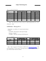
Measured Tr acker Data Out - Message I.D. 4
Output Rate: 1 Hz
Table 4-38 lists the binary and ASCII message data format for the measured tracker
data.
Example:
A0A200BC— Start Sequence and Payload Length
04036C0000937F0C0EAB46003F1A1E1D1D191D1A1A1D1F1D59423F1A1A...— Payload
****B0B3— Message Checksum and End Sequence
- 39 -
Laipac Technology Inc.
Table 4- 40 Measured Tracker Data Out
Binar y (Hex)
Name
Bytes
Scale
Example
Message ID
1
04
GPS Week
2
036C
GPS TOW
4
s*100
0000937F
Chans
1
0C
1st Svid
1
0E
Azimuth
1
Az*[2/3]
AB
Elev
1
El*2
46
State
2
003F
C/No 1
1
1A
C/No 2
1
1E
C/No 3
1
1D
C/No 4
1
1D
C/No 5
1
19
C/No 6
1
1D
C/No 7
1
1A
C/No 8
1
1A
C/No 9
1
1D
C/No 10
1
1F
2nd SVid
1
1D
Azimuth
1
Az*[2/3]
59
Elev
1
El*2
42
State
2
3F
C/No 1
1
1A
C/No 2
1
1A
Payload Length: 188 bytes
Units
None
s
deg
deg
Bitmap 1
deg
deg
Bitmap 1
ASCII (Decimal)
Scale
Example
4
876
37759
s÷ 100
12
14
256.5
÷ (2/3)
35
÷ 2
0 x BF
26
30
29
29
25
29
26
26
29
31
29
89
÷ (2/3)
66
÷ 2
63
26
63
1.For further information, go to Table 4-41
Note – The measurement of GPS Week item is expressed with ICD GPS week
format (between 0 and 1023)
Note – Message length is fixed to 188 bytes with nontracking channels reporting
zero values.
Table 4-41 TrktoNAVStruct.trk_status Field Definition
Field Definition
ACQ_SUCCESS
DELTA_CARPHASE_VALI
D
BIT_SYNC_DONE
SUBFRAME_SYNC_DONE
Hex
Descr iption
Value
0x0001 Set, if acq/reacq is done successfully
0x0002 Set, Integrated carrier phase is valid
0x0004 Set, Bit sync completed flag
0x0008 Set, Subframe sync has been done
- 40 -
Laipac Technology Inc.
CARRIER_PULLIN_DONE
0x0010 Set, Carrier pullin done
CODE_LOCKED
0x0020 Set, Code locked
ACQ_FAILED
0x0040 Set, Failed to acquire S/V
GOT_EPHEMERIS
0x0080 Set, Ephemeris data available
Note – When a channel is fully locked and all data is valid, the status shown is 0 x BF.
Raw Tr acker Data Out - Message I.D. 5
Not implementedfor TF30.
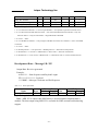
Software Ver sion Str ing (Response to Poll) - Message I.D. 6
Output Rate: Response to polling message
Example:
A0A20015— Start Sequence and Payload Length
0606312E322E30444B495431313920534D0000000000— Payload
0382B0B3— Message Checksum and End Sequence
Table 4- 42 Software Version String
Name
Bytes
Message ID
1
Character
20
Payload Length: 21 bytes
Binar y (Hex)
Scale
Example
06
1
Units
ASCII (Decimal)
Scale
Example
6
1. 06312E322E30444B495431313920534D0000000000
Note – Convert to symbol to assemble message (i.e., 0 x 4E is ‘N’). These are low
priority task and are not necessarily output at constant intervals.
Response: Clock Status Data - Message I.D. 7
Output Rate: 1 Hz or response to polling message
Example:
A0A20014— Start Sequence and Payload Length
0703BD021549240822317923DAEF— Payload
0598B0B3— Message Checksum and End Sequence
- 41 -
Laipac Technology Inc.
Table 4- 43 Clock Status Data Message
Name
Bytes
Message ID
1
GPS Week
2
GPS TOW
4
Svs
1
Clock Drift
4
Clock Bias
4
Estimated GPS
4
Time
Payload Length: 20 bytes
Binar y (Hex)
Units
Scale
Example
07
03BD
*100 002154924
s
08
2231
Hz
7923
nanosec
DAEF
millisec
ASCII (Decimal)
Scale
Example
7
957
349494.12
÷100
8
74289
128743715
349493999
Note – The mersurement of GPS week item is with Extended GPS week (=ICD
GPS week + 1024)
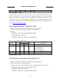
50 BPS Data – Message I.D. 8
Output Rate: As available (12.5 minute download time)
Example:
A0A2002B— Start Sequence and Payload Length
08xxxxxx— Payload
xxxxB0B3— Message Checksum and End Sequence
Table 4- 44 50 BPS Data
Binar y (Hex)
Name
Bytes
Scale
Example Units
Message ID
1
08
Channel
1
Sv I.D
1
Word[10]
40
Payload Length: 43 bytes per subframe (5 subframes per page)
ASCII (Decimal)
Scale
Example
8
Note – Data is logged in ICD format (available from www.navcen.uscg.gov). The
ICD specification is 30-bit words. The output above has been stripped of parity to
give a 240 bit frame instead of 300 bits.
- 42 -
Laipac Technology Inc.
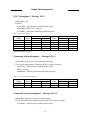
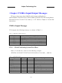
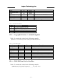
CPU Throughput – Message I.D. 9
Output Rate:1 Hz
Example:
A0A20009— Start Sequence and Payload Length
09003B0011001601E5— Payload
0151B0B3— Message Checksum and End Sequence
Table 4- 45 CPU Throughput
Name
Bytes
Message ID
1
SegStatMax
2
SegStatLat
2
AveTrkTime
2
Last MS
2
Payload Length: 9 bytes
Binar y (Hex)
Scale
Example
09
*186
003B
*186
60011
*186
60016
01E5
Units
millisec
millisec
millisec
millisec
ASCII (Decimal)
Scale
Example
9
.3172
÷186
.0914
÷186
.1183
÷186
485
Command Acknowledgment – Message I.D. 11
Output Rate: Response to successful input message
This is successful almanac (message ID 0x92) request example:
A0A20002— Start Sequence and Payload Length
0B92— Payload
009DB0B3— Message Checksum and End Sequence
Table 4- 46 Command Acknowledgment
Name
Bytes
Message ID
1
Ack. I.D.
1
Payload Length: 2 bytes
Binar y (Hex)
Scale
Example
0B
92
Units
ASCII (Decimal)
Scale
Example
11
146
Command NAcknowledgment – Message I.D. 12
Output Rate: Response to rejected input message
This is an unsuccessful almanac (message ID 0x92) request example:
A0A20002— Start Sequence and Payload Length
- 43 -
Laipac Technology Inc.
0C92— Payload
009EB0B3— Message Checksum and End Sequence
Table 4- 47 Command Nacknowledgment
Name
Bytes
Message ID
1
Nack. I.D.
1
Payload Length: 2 bytes
Binar y (Hex)
Scale
Example
0C
92
Units
ASCII (Decimal)
Scale
Example
12
146
Visible List – Message I.D. 13
Output Rate: Updated approximately every 2 minutes
Note – This is a variable length message. Only the number of visible satellites are
reported (as defined by Visible Svs in Table 4-48). Maximum is 12 satellites.
Example:
A0A2002A— Start Sequence and Payload Length
0D080700290038090133002C… xxxxxxxxxxxxxxxxx— Payload
xxxxB0B3— Message Checksum and End Sequence
Table 4- 48 Visible List
Name
Bytes
Message ID
1
Visible Svs
1
CH 1 – Sv
1
I.D.
CH 1 – Sv
2
Azimuth
CH 1 – Sv
2
Elevation
CH 2 – Sv
1
I.D.
CH 2 – Sv
2
Azimuth
CH 2 – Sv
2
Elevation
…
Payload Length: Variable
Binar y (Hex)
Scale
Example
0D
08
10
Units
ASCII (Decimal)
Scale
Example
13
8
16
002A
degrees
42
0038
degrees
56
09
9
0133
degrees
307
002C
degrees
44
- 44 -
Laipac Technology Inc.
Almanac Data - Message I.D. 14
Output Rate: Response to poll
Example:
A0A203A1— Start Sequence and Payload Length
0E01*************— Payload
****B0B3— Message Checksum and End Sequence
Table 4- 49 Almanac Data
Name
Message I.D.
Sv I.D.
Almanac week and
Status
Bytes
1
1
2
Almanac data
24
Package checksum
2
Binar y (Hex)
Scale
Example
0E
01
Satellite PRN Number 1
1101 First 10 bits is the Almanac
week.Next 5 bits have a zero
value. Last bit is 1.
…
This information is taken from
the 50BPS navigation message
broadcast by the satellite. This
information is the last 8 words in
the 5th subframe but with the
parity removed.2
4CA1 This is the checksum of the
preceding data in the payload. It
is calculated by arranging the
previous 26 bytes as 13 halfwords and then summing them.3
Payload Length: 30 bytes
1. Each satellite almanac entry is output in a single message.
2. There are 25 possible pages in subframe 5. Pages 1 through 24 contain satellite specific almanac
information which is output as part of the almanac data. Page 25 contains health status flags and the
almanac week number.
3. This checksum is not used for serial I/O data integrity. It is used internally for ensuring that almanac
information is valid.
Note – The data is actually packed and the exact format of this representation and
packing method can be extracted from the ICD-GPS-2000 document. The ICD-GPS2000 document describes the data format of each GPS navigation sub-frame and is
available on the web at http://www.arinc.com/gps.
- 45 -
Laipac Technology Inc.
Ephemer is Data (Response to Poll) – Message I.D. 15
The ephemeris data that is polled from the receiver is in a special SiRF format
based on the ICD- GPS -200 format for ephemeris data.
OkToSend - Message I.D. 18
Output Rate: Trickle Power CPU on/off indicator
Example:
A0A20002— Start Sequence and Payload Length
1200— Payload
0012B0B3— Message Checksum and End Sequence
Table 4- 50 Ephemeris Data
Binar y (Hex)
Scale
Example
12
00
Name
Bytes
Message I.D.
1
1
Send Indicator
1
Payload Length: 2 bytes
Units
ASCII (Decimal)
Scale
Example
12
00
1.0 implies that CPU is about to go OFF, OkToSend==NO, 1 implies CPU has just come ON,
OkToSend==YES
Navigation Par ameter s (Response to Poll) – Message I.D. 19
Output Rate:1 Response to Poll
Example:
A0A20018— Start Sequence and Payload Length
130100000000011E3C0104001E004B1E00000500016400C8— Payload
022DB0B3— Message Checksum and End Sequence
Table 4- 51 Navigation Parameters
Binar y (Hex)
Name
Bytes
Units
Scale
Message ID
Reserved
Altitude Hold Mode
Altitude Hold Source
Altitude Source Input
Degraded Mode 1
1
4
1
1
2
1
Example
13
00
00
0000
01
- 46 -
meters
ASCII
(Decimal)
Scale Example
19
0
0
0
1
Laipac Technology Inc.
Degraded Timeout
DR Timeout
Track Smooth Mode
Static Navigation
3SV Least Squares
Reserved
DOP Mask Mode 2
Navigation Elevation
Mask
Navigation Power Mask
Reserved
DGPS Source
DGPS Mode 3
DGPS Timeout
Reserved
LP Push-to-Fix
LP On-time
LP Interval
LP User Tasks Enabled
LP User Task Interval
LP Power Cycling
Enabled
LP Max. Acq. Search
Time
LP Max. Off Time
Reserved
Reserved
Payload Length: 65 bytes
1
1
1
1
1
4
1
2
1E
3C
01
1
4
1
1
1
4
1
4
4
1
4
1
seconds
seconds
30
60
1
04
4
00
1E
0
30
seconds
4
4
4
4
1. See Table 4-13.
2. See Table 4-14.
3. See Table 4-15
Navigation Libr ar y Measurement Data - Message I.D. 28
Output Rate: Every measurement cycle (full power / continuous : 1Hz)
Example:
A0A20038— Start Sequence and Payload Length
1C00000660D015F143F62C4113F42FF3FBE95E417B235C468C6964B8FBC5
82415CF1C375301734.....03E801F400000000— Payload
1533B0B3— Message Checksum and End Sequence
- 47 -
Laipac Technology Inc.
Table 4- 52 Measurement Data
Binar y (Hex)
Name
Bytes
Units
Scale
Example
1C
Message I.D.
Channel
00
Time Tag
000660D0
Satellite ID
ms
15
GPS Software Time
F143F62C
4113F42F
F3FBE95E
417B235C
468C6964
Pseudo-range
Carrier Frequency
Carrier Phase
B8FBC582
415CF1C3
7530
Time in Track
Sync Flags
17
C/No 1
34
C/No 2
C/No 3
C/No 4
C/No 5
C/No 6
C/No 7
C/No 8
C/No 9
C/No 10
Delta Range Interval
03E801F4
Mean Delta Range Time
01F4
Extrapolation Time
0000
Phase Error Count
00
Low Power Count
00
Payload Length: 56 bytes
Tabl e 4- 53 Sync Flag Fields
Bit Fields
Description
[0]
Coherent Integration Time
0 = 2ms
1 = 10ms
Synch State
00 = Not aligned
01 = Consistent code epoch alignment
10 = Consistent data bit alignment
11 = No millisecond errors
[2:1]
ASCII
(Decimal)
Scale Example
- 48 -
ms
m
ms
dB-Hz
dB-Hz
dB-Hz
dB-Hz
dB-Hz
dB-Hz
dB-Hz
dB-Hz
dB-Hz
dB-Hz
m
ms
ms
2.4921113
696e+005
2.1016756
638e+007
1.6756767
578e+004
4.4345542
262e+004
10600
23
43
43
43
43
43
43
43
43
43
43
1000
500
0
0
Laipac Technology Inc.
[4:3]
Autocorrelation Detection State
00 = Verified not an autocorrelation
01 = Testing in progress
10 = Strong signal, autocorrelation detection not run
11 = Not used
Tabl e 4- 54 Detailed Description of the Measurement Data
Name
Message I.D.
Channel
Time Tag
Satellite ID
GPS Software
Time
Pseudo-range
Carrier
Frequency
Carrier Phase
Time in Track
Sync Flags
Descr iption
Message I.D. number.
Receiver channel number for a given satellite being searched
or tracked.
This is the Time Tag in milliseconds of the measurement block
in the receiver software time.
Satellite or Space Vehicle (SV) I.D. number or Pseudo-random
Noise (PRN) number.
This is GPS Time or Time of Week (TOW) estimated by the
software in milliseconds.
This is the generated pseudo range measurement for a
particular SV.
This is can be interpreted in two ways:
1) The delta-pseudo range normalized by the reciprocal of the
delta pseudo range measurement interval.
2) The frequency from the AFC loop. If, for example, the delta
pseudo range interval computation for a particular channel
is zero, then it can be the AFC measurement, otherwise it is a
delta-pseudo range computation.
This is the integrated carrier phase given in meters.
The Time in Track counts how long a particular SV has been
in track. For any count greater than zero (0), a generated
pseudo range is present for a particular channel. The length of
time in track is a
measure of how large the pull-in error may be.
This byte contains two a two bit fields that report the
integration inter-val and sync value achieved for a particular
channel.
1)Bit 0: Coherent Integration Interval (0 = 2 milliseconds, 1 =
10 milli- seconds)
2) Bits: (1 2) = Synchronization
3) Bit: (2 1)
Value: {0 0} Not Aligned
Value: {0 1} Consistent Code Epoch Alignment
Value: {1 0} Consistent Data Bit Alignment
Value: {1 1} No Millisecond Errors
- 49 -
Laipac Technology Inc.
Tabl e 4- 55 Detailed Description of the Measurement Data (Continued)
Name
C/No 1
Descr iption
This array of Carrier To Noise Ratios is the average signal
power in dB-Hz for each of the 100-millisecond intervals in the
previous second or last epoch for each particular SV being track
in a channel.First 100 millisecond measurement
C/No 2
Second 100 millisecond measurement
C/No 3
Third 100 millisecond measurement
C/No 4
Fourth 100 millisecond measurement
C/No 5
Fifth 100 millisecond measurement
C/No 6
Sixth 100 millisecond measurement
C/No 7
Seventh 100 millisecond measurement
C/No 8
Eighth 100 millisecond measurement
C/No 9
Ninth 100 millisecond measurement
C/No 10
Tenth 100 millisecond measurement
Delta Range
This is the delta-pseudo range measurement interval for the
Interval
preceding second. A value of zero indicated that the receiver has
an AFC measurement or no measurement in the Carrier
Frequency field for a particular channel.
Mean Delta Range This is the mean calculated time of the delta-pseudo range
Time
interval in milliseconds measured from the end of the interval
backwards Extrapolation Time This is the pseudo range
extrapolation time in milliseconds, to reach the common Time
tag value.
Phase Error Count This is the count of the phase errors greater than 60 Degrees
measured in the preceding second as defined for a particular
channel.
Low Power Count This is the low power measurements for signals less than 28 dBHz in the preceding second as defined for a particular channel
Navigation Libr ar y DGPS Data - Message I.D. 29
Output Rate: Every measurement cycle (full power / continuous : 1Hz)
Example:
A0A2001A— Start Sequence and Payload Length
1D000F00B501BFC97C673CAAAAAB3FBFFE1240A0000040A00000-Payload
0956B0B3— Message Checksum and End Sequence
Table 4- 56 Measurement Data
Binar y (Hex)
Name
Bytes
Units
Scale
Message I.D.
1
- 50 -
Example
1D
ASCII
(Decimal)
Scale Example
Laipac Technology Inc.
Satellite ID
IOD
Source 1
Pseudo-range Correction
Pseudo-range rate
Correction
Correction Age
Reserved
Reserved
Payload Length: 26 bytes
2
2
1
4
4
000F
00B5
01
BFC97C67
3CAAAAAB
ms
m/s
4
4
4
3FBFFE12
s
1. 0 = Use no corrections, 1 = Use WAAS channel, 2 = Use external source, 3 = Use Internal Beacon, 4
= Set DGPS Corrections
Navigation Libr ar y SV State Data - Message I.D. 30
Output Rate: Every measurement cycle (full power / continuous : 1Hz)
Example:
A0A20053— Start Sequence and Payload Length
1E15....2C64E99D01....408906C8— Payload
2360B0B3— Message Checksum and End Sequence
Table 4- 57 SV State Data
Binar y (Hex)
Name
Bytes
Units
Scale
Message I.D.
Satellite ID
GPS Time
Position X
Position Y
Position Z
Velocity X
Velocity Y
Velocity Z
Clock Bias
Clock Drift
Ephemeris Flag 1
Reserved
Ionospheric Delay
Payload Length: 83 bytes
1
1
8
8
8
8
8
8
8
8
4
1
8
4
Example
1E
15
2C64E99D
01
408906C8
s
m
m
m
m/s
m/s
m/s
s
/s
m
ASCII
(Decimal)
Scale Example
744810909
1
1082721992
1. 0 = no valid SV state, 1 = SV state calculated from ephemeris, 2 = Satellite state calculated from
almanac
- 51 -
Laipac Technology Inc.
Navigation Libr ar y Initialization Data - Message I.D. 31
Output Rate: Every measurement cycle (full power / continuous : 1Hz)
Example:
A0A20054— Start Sequence and Payload Length
1F....00000000000001001E000F....00....000000000F....00....02....043402....
....02— Payload
0E27B0B3— Message Checksum and End Sequence
Table 4- 58 Measurement Data
Binar y (Hex)
Name
Bytes
Scale
Message I.D.
Reserved
Altitude Mode 1
Altitude Source
Altitude
Degraded Mode 2
Degraded Timeout
Dead-reckoning Timeout
Reserved
Track Smoothing Mode 3
Reserved
Reserved
Reserved
Reserved
DGPS Selection 4
DGPS Timeout
Elevation Nav. Mask
Reserved
Reserved
Reserved
Reserved
Reserved
Static Nav.Mode 5
Reserved
Position X
Position Y
Position Z
Position Init. Source 6
GPS Time
1
1
1
1
4
1
2
2
2
1
1
2
2
2
1
2
2
2
1
2
1
2
1
2
8
8
8
1
8
- 52 -
Example
1E
ASCII
Units
(Decimal)
Scale Example
00
00
00000000
01
001E
000F
0
0
0
1
30
15
00
0
00
0
02
2
Laipac Technology Inc.
GPS Week
Time Init. Source 7
Drift
Drift Init. Source 8
Payload Length: 84 bytes
2
1
8
1
0434
02
1076
2
02
2
1. 0 = Use last know altitude 1 = Use user input altitude 2 = Use dynamic input from external source
2. 0 = Use direction hold and then time hold 1 = Use time hold and then direction hold 2 = Only use
direction hold 3 = Only use time hold 4 = Degraded mode is disabled
3. 0 = True 1 = False
4. 0 = Use DGPS if available 1 = Only navigate if DGPS corrections are available 2 = Never use DGPS
corrections
5. 0 = True 1 = False
6. 0 = ROM position 1 = User position 2 = SRAM position 3 = Network assisted position
7. 0 = ROM time 1 = User time 2 = SRAM time 3 = RTC time 4 = Network assisted time
8. 0 = ROM clock 1 = User clock 2 = SRAM clock 3 = Calibration clock 4 = Network assisted clock
Development Data – Message I.D. 255
Output Rate: Receiver generated
Example:
A0A2****— Start Sequence and Payload Length
FF**************— Payload
****B0B3— Message Checksum and End Sequence
Table 4- 59 Development Data
Name
Bytes
Message ID
1
Payload Length: Variable
Binar y (Hex)
Scale
Example Units
FF
ASCII (Decimal)
Scale
Example
255
Note – MID 255 is output when SiRF binary is selected and development data is
enabled. The data output using MID 255 is essential for SiRF assisted troubleshooting
support.
- 53 -
Laipac Technology Inc.
Additional Infor mation
Tr icklePower Oper ation in DGPS Mode
When in TricklePower mode, serial port DGPS corrections are supported. The CPU
goes into sleep mode but will wake up in response to any interrupt. This includes
UART’s. Messages received during the TricklePower ‘off’ period are buffered and
processed when the receiver awakens for the next TricklePower cycle.
GPS Week Repor ting
Since Aug, 22, 1999, the GPS week roll from 1023 weeks to 0 weeks is in
accordance with the ICD-GPS-200 specifications. To maintain roll over compliance,
SiRF reports the ICD GPS week between 0 and 1023. If the user needs to have access
to the Extended GPS week (ICD GPS week + 1024) this information is available
through the Clock Status Message (007) under the Poll menu.
NMEA Protocol in Tr icklePower Mode
The NMEA standard is generally used in continuous update mode at some
predefined rate. This mode is perfectly compatible with all SiRF TricklePower and
Push-to-Fix modes of operations. There is no mechanism in NMEA that indicates to a
host application when the receiver is on or in standby mode. If the receiver is in
standby mode (chip set OFF, CPU in standby), then no serial communication is
possible for output of NMEA data or receiving SiRF proprietary NMEA input
commands. To establish reliable communication, the user must repower the receiver
and send commands while the unit is in full-power mode (during start-up) and prior to
reverting to TricklePower operation. Alternatively, the host application could send
commands (i.e., poll for position) repeatedly until the request has been completed.
In Trickle-Power mode, the user is required to select an update rate (seconds
between data output) and On Time (milli-seconds the chipset is on). When the user
changes to NMEA mode, the option to set the output rate for each of the selected
NMEA messages is also required. These values are multiplied by the TricklePower
update rate value as shown in Table 4-58.
- 54 -
Laipac Technology Inc.
Table 4- 60 NMEA Data Rates Under Trickle Power Operation
Power Mode
Continuous
Tr ickle Power Tr ickle Power
Tr ickle Power
Update Rate
1 every second
1 every second
1 every 5
seconds
1 every 8 seconds
On Time
1000
2000
4000
6000
NMEA Update
1 every 5
1 every 2
1 every second
1 every 5 seconds
Rate
seconds
seconds
Message
1 every 5
1 every 10
1 every 40
1 every second
Output Rate
seconds
seconds
seconds
Note – The On Time of the chip set has no effect on the output data rates.
- 55 -
Laipac Technology Inc.
Chapter 5 NMEA Input/Output Messages
TF30 m ay also o utp ut data in NM EA-0183 format as defined by th e
National Marine Electronics Asso ciation (NMEA), St and ar d For Inte rfacing Marine
Electronic D evice s, Ver sion 2. 20, J anua ry 1, 1 997. Refer to Chapter 4 for det ailed
inst ructions .
NMEA Output Messages
TF 30 ou tp ut s th e fol lowing m essa ges as s hown in Table 5 -1:
Tabl e 5- 1 NMEA-0183 Ou tput Messag es
NMEA Recor d
GGA
GLL
GSA
GSV
RMC
VTG
Descr iption
Global positioning syste m fixed data
Geographic position - latitu de/longitude
GNSS DOP and active satellites
GNSS satellites in view
Recomm ended minimum specific GNSS data
Course over g round a nd g round spee d
GGA — Global Positioning System Fixed Data
Table 5-2 contains the values for the following example:
$GPGGA,161229.487,3723.2475,N,12158.3416,W,1,07,1.0,9.0,M, , , ,0000*18
Tabl e 5- 2 GGA Data Format
Name
Message ID
UTC Time
Latitude
N/S Indicator
Longitude
E/W Indicator
Position Fix Indicator
Satellites Used
HDOP
MSL Altitude 1
Example
$GPGGA
161229.487
3723.2475
N
12158.3416
W
1
07
1.0
9.0
Units
meters
- 56 -
Descr iption
GGA protocol header
hhmmss.sss
ddmm.mmmm
N=north or S=south
dddmm.mmmm
E=east or W=west
See Table 5-3
Range 0 to 12
Horizontal Dilution of Precision
Laipac Technology Inc.
Units
Geoid Separation 1
Units
Age of Diff. Corr.
Diff. Ref. Station ID
Checksum
<CR> <LF>
M
M
meters
meters
meters
second
Null fields when DGPS is not used
0000
*18
End of message termination
1.Values are WGS84 ellipsoid heights.
Tabl e 5- 3 Position Fix Indicator
Value
0
1
2
3
Descr iption
Fix not available or invalid
GPS SPS Mode, fix valid
Differential GPS, SPS Mode, fix valid
GPS PPS Mode, fix valid
GLL— Geogr aphic Position - Latitude/Longitude
Table 5-4 contains the values for the following example:
$GPGLL,3723.2475,N,12158.3416,W,161229.487,A*2C
Tabl e 5- 4 GLL Data Format
Name
Message ID
Latitude
N/S Indicator
Longitude
E/W Indicator
UTC Position
Status
Checksum
<CR> <LF>
Example
$GPGLL
3723.2475
N
12158.3416
W
161229.487
A
*2C
Units
Descr iption
GLL protocol header
ddmm.mmmm
N=north or S=south
dddmm.mmmm
E=east or W=west
hhmmss.sss
A=data valid or V=data not valid
End of message termination
GSA— GNSS DOP and Active Satellites
Table 5-5 contains the values for the following example:
$GPGSA,A,3,07,02,26,27,09,04,15, , , , , ,1.8,1.0,1.5*33
- 57 -
Laipac Technology Inc.
Tabl e 5- 5 GSA Data Format
Name
Message ID
Mode 1
Mode 2
Satellite Used 1
Satellite Used 1
.... ....
Satellite Used 1
PDOP
HDOP
VDOP
Checksum
<CR> <LF>
Example
$GPGSA
A
3
07
02
Units
Descr iption
GSA protocol header
See Table 5-6
See Table 5-7
Sv on Channel 1
Sv on Channel 2
Sv on Channel 12
Position Dilution of Precision
Horizontal Dilution of Precision
Vertical Dilution of Precision
1.8
1.0
1.5
*33
End of message termination
1. Satellite used in solution.
Tabl e 5- 6 Mode 1
Value
M
A
Descr iption
Manual— forced to operate in 2D or 3D mode
2Dautomatic— allowed to automatically switch 2D/3D
Tabl e 5- 7 Mode 2
Value
1
2
3
Descr iption
Fix Not Available
2D
3D
GSV— GNSS Satellites in View
Table 5-8 contains the values for the following example:
$GPGSV,2,1,07,07,79,048,42,02,51,062,43,26,36,256,42,27,27,138,42*71
$GPGSV,2,2,07,09,23,313,42,04,19,159,41,15,12,041,42*41
Tabl e 5- 8 GSV Data Format
Name
Message ID
Number of
Messages 1
Message
Number 1
Satellites in
Example
$GPGSV
2
1
Units
Descr iption
GSV protocol header
Range 1 t o 3
Range 1 t o 3
07
- 58 -
Laipac Technology Inc.
View
Satellite ID
Elevation
Azimuth
SNR (C/No)
.... ....
Satellite ID
Elevation
Azimuth
SNR (C/No)
Checksum
<CR> <LF>
07
79
048
42
27
27
138
42
*71
degrees
degrees
dBHz
Channel 1 (Range 1 to 32)
Channel 1 (Maximum 90)
Channel 1 (True, Range 0 to 359)
Range 0 to 99, null when not tracking
degrees
degrees
dBHz
Channel 4 (Range 1 to 32)
Channel 4 (Maximum 90)
Channel 4 (True, Range 0 to 359)
Range 0 to 99, null when not tracking
End of message termination
1.Depending on the number of satellites tracked multiple messages of GSV data may be required.
RMC— Recommended Minimum Specific GNSS Data
Table 5-9 contains the values for the following example:
$GPRMC,161229.487,A,3723.2475,N,12158.3416,W,0.13,309.62,120598, ,*10
Tabl e 5- 9 RMC Data Format
Name
Example
Message ID
$GPRMC
UTC Time
161229.487
Status
A
Latitude
3723.2475
N/S Indicator
N
Longitude
12158.3416
E/W Indicator
W
Speed Over
0.13
Ground
Course Over
309.62
Ground
Date
120598
Magnetic
Variation 1
Checksum *10
<CR> <LF>
Units
Descr iption
RMC protocol header
hhmmss.sss
A=data valid or V=data not valid
ddmm.mmmm
N=north or S=south
dddmm.mmmm
E=east or W=west
knots
degrees
True
degrees
Ddmmyy
E=east or W=west
End of message termination
1.All “course over ground” data are geodetic WGS84 directions.
- 59 -
Laipac Technology Inc.
VTG— Cour se Over Ground and Ground Speed
Table 5-10 contains the values for the following example:
$GPVTG,309.62,T, ,M,0.13,N,0.2,K*6E
Tabl e 5- 10 VTG Data Format
Name
Message ID
Course
Reference
Course
Reference
Speed
Units
Speed
Units
Checksum
<CR> <LF>
Example
$GPVTG
309.62
T
Units
degrees
degrees
M
0.13
N
0.2
K
*6E
knots
knots
km/hr
Descr iption
VTG protocol header
Measured heading
True
Measured heading
Magnetic 1
Measured horizontal speed
Measured horizontal speed
Kilometers per hour
End of message termination
1. All “course over ground” data are geodetic WGS84 directions.
SiRF Propr ietar y NMEA Input Messages
NMEA input messages are provided to allow you to control the Evaluation Unit
while in NMEA protocol mode. The Evaluation Unit may be put into NMEA mode by
sending the SiRF Binary protocol message “Switch To NMEA Protocol - Message I.D.
129” using a user program or using Sirfdemo.exe and selecting Switch to NMEA
Protocol from the Action menu. If the receiver is in SiRF Binary mode, all NMEA
input messages are ignored. Once the receiver is put into NMEA mode, the following
messages may be used to command the module.
Tr anspor t Message
Star t Sequence
$PSRF<MID>1
Payload
Data 2
Checksum
*CKSUM 3
End Sequence
<CR> <LF>4
1.Message Identifier consisting of three numeric characters. Input messages begin at MID 100.
2.Message specific data. Refer to a specific message section for <data>...<data> definition.
- 60 -
Laipac Technology Inc.
3.CKSUM is a two-hex character checksum as defined in the NMEA specification. Use of checksums
is required on all input messages.
4. Each message is terminated using Carriage Return (CR) Line Feed (LF) which is \r\n which is hex
0D 0A. Because \r\n are not printable ASCII characters, they are omitted from the example strings, but
must be sent to terminate the message and cause the receiver to process that input message.
Note – All fields in all proprietary NMEA messages are required, none are optional.
All NMEA messages are comma delimited.
SiRF NMEA Input Messages
Message
Set Serial Port
Navigation Initialization
Set DGPS Port
Query/Rate Control
MID 1
LLA Navigation
Initialization
Development Data
On/Off
Descr iption
100
101
102
103
Set PORT A parameters and protocol
Parameters required for start using X/Y/Z
Set PORT B parameters for DGPS input
Query standard NMEA message and/or set output
rate
104 Parameters required for start using Lat/Lon/Alt 2
105 Development Data messages On/Off
1. Message Identification (MID).
2. Input coordinates must be WGS84.
SetSer ialPor t
This command message is used to set the protocol (SiRF Binary or NMEA) and/or
the communication parameters (baud, data bits, stop bits, parity). Generally, this
command is used to switch the module back to SiRF Binary protocol mode where a
more extensive command message set is available. When a valid message is received,
the parameters are stored in battery-backed SRAM and then the Evaluation Unit
restarts using the saved parameters.
Table 5-11 contains the input values for the following example:
Switch to SiRF Binary protocol at 9600,8,N,1
$PSRF100,0,9600,8,1,0*0C
Tabl e 5- 11 Set Serial Port Data Format
Name
Message ID
Protocol
Example
$PSRF100
0
Units
Descr iption
PSRF100 protocol header
0=SiRF Binary, 1=NMEA
- 61 -
Laipac Technology Inc.
Baud
DataBits
StopBits
Parity
Checksum
<CR> <LF>
9600
8
1
0
*0C
4800, 9600, 19200, 38400
8,7 1
0,1
0=None, 1=Odd, 2=Even
End of message termination
1.Only valid for 8 data bits, 1stop bit, and no parity.
NaviagtionInitialization
This command is used to initialize the module for a warm start, by providing
current position (in X, Y, Z coordinates), clock offset, and time. This enables the
TF30 to search for the correct satellite signals at the correct signal parameters.
Correct initialization parameters enable TF30 to acquire signals quickly.
Table 5-12 contains the input values for the following example:
Start using known position and time.
$PSRF101,-2686700,-4304200,3851624,96000,497260,921,12,3*7F
Tabl e 5- 12 Navigation Initialization Data Format
Name
Message ID
ECEF X
ECEF Y
ECEF Z
ClkOffset
TimeOfWeek
WeekNo
ChannelCount
ResetCfg
Checksum
<CR> <LF>
Example
$PSRF101
-2686700
-4304200
3851624
96000
497260
921
12
3
*7F
Units
meters
meters
meters
Hz
seconds
Descr iption
PSRF101 protocol header
X coordinate position
Y coordinate position
Z coordinate position
Clock Offset of TF 30 1
GPS Time Of Week
GPS Week Number
Range 1 to 12
See Table 5-13
End of message termination
1. Use 0 for last saved value if available. If this is unavailable, a default value of 96,000 will be used.
Tabl e 5- 13 Reset Configuration
Hex
0x01
0x02
0x04
Descr iption
Data Valid— Warm/Hot Starts=1
Clear Ephemeris— Warm Start=1
Clear Memory— Cold Start=1
- 62 -
Laipac Technology Inc.
SetDGPSPor t
This command is used to control Serial Port B which is an input-only serial port
used to receive RTCM differential corrections. Differential receivers may output
corrections using different communication parameters. The default communication
parameters for PORT B are 9600 baud, 8 data bits, stop bit, and no parity. If a DGPS
receiver is used which has different communication parameters, use this command to
allow the receiver to correctly decode the data. When a valid message is received, the
parameters are stored in battery-backed SRAM and then the receiver restarts using the
saved parameters.
Table 5-14 contains the input values for the following example:
Set DGPS Port to be 9600,8,N,1.
$PSRF102,9600,8,1,0*12
Tabl e 5- 14 Set DGPS Port Data Format
Name
Example
Message ID $PSRF102
Baud
9600
DataBits
8
StopBits
1
Parity
0
Checksum
*12
<CR> <LF>
Units
Descr iption
PSRF102 protocol header
4800, 9600, 19200, 38400
8,7
0,1
0=None, 1=Odd, 2=Even
End of message termination
Quer y/Rate Control
This command is used to control the output of standard NMEA messages GGA,
GLL, GSA, GSV, RMC, and VTG. Using this command message, standard NMEA
messages may be polled once, or setup for periodic output. Checksums may also be
enabled or disabled depending on the needs of the receiving program. NMEA
message settings are saved in battery-backed memory for each entry when the
message is accepted.
Table 5-15 contains the input values for the following examples:
1. Query the GGA message with checksum enabled
$PSRF103,00,01,00,01*25
2. Enable VTG message for a 1 Hz constant output with checksum enabled
$PSRF103,05,00,01,01*20
- 63 -
Laipac Technology Inc.
3. Disable VTG message
$PSRF103,05,00,00,01*21
Tabl e 5- 15 Query/Rate Control Data Format (See example 1.)
Name
Example
Units
Descr iption
Message ID $PSRF103
PSRF103 protocol header
Msg
00
See Table 5-16
Mode
01
0=SetRate, 1=Query
Rate
00
seconds Output— off=0, max=255
CksumEnabe
01
0=Disable Checksum, 1=Enable Checksum
Checksum
*25
<CR> <LF>
End of message termination
Table 5- 16 Messages
Value
Descr iption
0
GGA
1
GLL
2
GSA
3
GSV
4
RMC
5
VTG
Note – In Trickle Power mode, update rate is specified by the user. When you
witch to NMEA protocol, message update rate is also required. The resulting update
rate is the product of the Trickle Power Update rate AND the NMEA update rate (i.e.
Trickle Power update rate = 2 seconds, NMEA update rate = 5 seconds, resulting
update rate is every 10 seconds, (2 X 5 = 10)).
LLANaviagtionInitialization
This command is used to initialize the module for a warm start, by providing current
position (in latitude, longitude, and altitude coordinates), clock offset, and time. This
enables the receiver to search for the correct satellite signals at the correct signal
parameters. Correct initialization parameters enable the receiver to acquire signals
quickly.
Table 5-17 contains the input values for the following example:
Start using known position and time.
$PSRF104,37.3875111,-121.97232,0,96000,237759,922,12,3*37
- 64 -
Laipac Technology Inc.
Table 5- 17 LLA Navigation Initialization Data Format
Name
Example
Units
Message ID
$PSRF104
37.3875111 degrees
Lat
-121.97232 degrees
Lon
0
Alt
meters
ClkOffset
95000
Hz
237759
seconds
TimeOfWeek
922
WeekNo
ChannelCount
12
ResetCfg
3
Checksum
*37
<CR> <LF>
Descr iption
PSRF104 protocol header
Latitude position (Range 90 to -90)
Longitude position (Range 180 to -180)
Altitude position
Clock Offset of the Evaluation Unit 1
GPS Time Of Week
GPS Week Number
Range 1 to 12
See Table 5-18
End of message termination
1.Use 0 for last saved value if available. If this is unavailable, a default value of 96,000 will be used.
Tabl e 5- 18 Reset Configuration
Hex
0x01
0x02
0x04
Descr iption
Data Valid— Warm/Hot Starts=1
Clear Ephemeris— Warm Start=1
Clear Memory— Cold Start=1
Development Data On/Off
Use this command to enable development data information if you are having
trouble getting commands accepted. Invalid commands generate debug information
that enables the user to determine the source of the command rejection. Common
reasons for input command rejection are invalid checksum or parameter out of
specified range.
Table 5-19 contains the input values for the following examples:
1. Debug On
$PSRF105,1*3E
2. Debug Off
$PSRF105,0*3F
Tabl e 5- 19 Development Data On/Off Data Format
Name
Example
Message ID $PSRF105
Debug
1
Checksum
*3E
<CR> <LF>
Units
Descr iption
PSRF105 protocol header
0=Off, 1=On
End of message termination
- 65 -