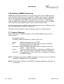
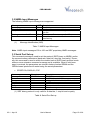
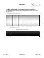
1
GPS Firmware for GSD4e-based
Products
A Description of the standard NMEA GPS firmware provided
on Vincotech’s GPS modules based on SiRFstarIV – GSD4e
A2100
User’s Manual
Version 0.1
Firmware Revision 3.6.0
PRELIMINARY
PRELIMINARY
Revision History
Rev. Date
0.1 04-16-10
Description
Initial draft
mm-dd-yy
V0.1 - Apr-10
User’s Manual
Page 2 of 28
PRELIMINARY
Disclaimer
THIS DOCUMENT CONTAINS PROPRIETARY INFORMATION OF VINCOTECH
GMBH. IT MAY NOT BE COPIED OR TRANSMITTED BY ANY MEANS, PASSED
TO OTHERS, OR STORED IN ANY RETRIEVAL SYSTEM OR MEDIA, WITHOUT
PRIOR CONSENT OF VINCOTECH OR ITS AUTHORIZED AGENTS.
THE INFORMATION IN THIS DOCUMENT IS, TO THE BEST OF OUR
KNOWLEDGE, ENTIRELY CORRECT. HOWEVER, VINCOTECH CAN NEITHER
ACCEPT LIABILITY FOR ANY INACCURACIES, OR THE CONSEQUENCES
THEREOF, NOR FOR ANY LIABILITY ARISING FROM THE USE OR
APPLICATION OF ANY CIRCUIT, PRODUCT, OR EXAMPLE SHOWN IN THE
DOCUMENT.
THE PRODUCT (HARD- AND SOFTWARE) DESCRIBED IN THIS DOCUMENTATION IS NOT AUTHORIZED FOR USE IN LIFE SUPPORT DEVICES OR
SYSTEMS WITHOUT THE EXPRESS WRITTEN APPROVAL OF VINCOTECH.
THIS DOCUMENT MAY PROVIDE LINKS TO OTHER WORLD WIDE WEB SITES
OR RESOURCES. BECAUSE VINCOTECH HAS NO CONTROL OVER SUCH
SITES AND RESOURCES, VINCOTECH SHALL NOT BE RESPONSIBLE FOR
THE AVAILABILITY OF SUCH EXTERNAL SITES OR RESOURCES, AND DOES
NOT ENDORSE AND IS NOT RESPONSIBLE OR LIABLE FOR ANY CONTENT,
ADVERTISING, PRODUCTS, OR OTHER MATERIALS ON OR AVAILABLE
FROM SUCH SITES OR RESOURCES. VINCOTECH SHALL NOT BE
RESPONSIBLE OR LIABLE, DIRECTLY OR INDIRECTLY, FOR ANY DAMAGE
OR LOSS CAUSED OR ALLEGED TO BE CAUSED BY OR IN CONNECTION
WITH USE OF OR RELIANCE ON ANY SUCH CONTENT, GOODS OR
SERVICES AVAILABLE ON OR THROUGH ANY SUCH SITE OR RESOURCE.
VINCOTECH RESERVES THE RIGHT TO CHANGE, MODIFY, OR IMPROVE
THIS DOCUMENT OR THE PRODUCT DESCRIBED HEREIN, AS SEEN FIT BY
VINCOTECH WITHOUT FURTHER NOTICE.
V0.1 - Apr-10
User’s Manual
Page 3 of 28
PRELIMINARY
Table of Contents
1 Introduction ........................................................................................................ 5
1.1 Serial Port Configuration ................................................................................... 5
1.2 Cold Start Behaviour ......................................................................................... 6
1.2.1 Additional Output Messages....................................................................................... 6
1.2.2 InstantFix – Extended Ephemeris Support ................................................................. 6
2 Standard NMEA Sentences ............................................................................... 7
2.1 Introduction ....................................................................................................... 7
2.2 Supported NMEA Sentences ............................................................................ 7
2.2.1 GGA - Global Positioning System Fix Data ................................................................ 8
2.2.2 VTG – Course Over Ground and Ground Speed ....................................................... 9
2.2.3 RMC - Recommended Minimum Specific GPS Data ............................................... 10
2.2.4 GSA - GPS DOP and Active Satellites ..................................................................... 11
2.2.5 GSV – GPS Satellites in View .................................................................................. 12
2.2.6 GLL – Latitude, Longitude, UTC and status ............................................................. 13
3 Proprietary NMEA Sentences ......................................................................... 14
3.1 Transport Message ......................................................................................... 14
3.2 NMEA Input Messages ................................................................................... 15
3.3 Serial Port Set-up............................................................................................ 15
3.4 Reset Configuration (SiRF’s original: NavigationInitialization) ........................ 16
3.5 Query/Rate control .......................................................................................... 17
3.6 Development Data On/Off............................................................................... 18
3.7 Select Datum .................................................................................................. 19
3.8 Shut-Down Module.......................................................................................... 19
4 NMEA and Binary mode .................................................................................. 20
4.1 From NMEA to Binary Mode ........................................................................... 20
4.2 From Binary to NMEA Mode ........................................................................... 21
5 Important Binary Commands .......................................................................... 23
5.1 Static Mode ..................................................................................................... 23
5.2 SBAS Support ................................................................................................. 24
5.3 SiRFawareTM Mode ......................................................................................... 25
5.4 Shut-Down Module.......................................................................................... 25
6 Related Information ......................................................................................... 27
6.1 Contact............................................................................................................ 27
6.2 Related Documents......................................................................................... 27
6.3 Related Tools .................................................................................................. 27
7 List of Tables .................................................................................................... 28
V0.1 - Apr-10
User’s Manual
Page 4 of 28
PRELIMINARY
1 Introduction
This document contains a description of NMEA output sentences, NMEA commands, and special OSP / Binary Protocol commands which are implemented in the
standard GPS firmware used in all GPS modules based on the SiRFstarIV GSD4e
chip: A2100’s. For more details of the original SiRF firmware please see chapter
“6.2 Related Documents”.
This revision of the manual refers to firmware 4.0.1!
The purpose of this paper is the explanation of the behavior of the “NMEA” interface, i.e. a description of the outputs coming from this interface, and a summary of
the commands that can be issued to this interface. In addition it shows usage of
SiRFawareTM and PTF mode. This will allow easy and full adjustment and control of
the module.
1.1 Serial Port Configuration
The firmware supports the bi-directional serial interface of Vincotech’s GPS modules. It is implemented by use of the full duplex UART (Universal Asynchronous
Receiver Transmitter) interface of the GPS processor. Please note that it is necessary to configure the module with an external configuration resistor for UART mode
with the standard 4.0.1 firmware.
•
•
•
For the communication with UART the use of a kind of terminal program or
another appropriate method is necessary.
NMEA communication is always on port 0 (pin Tx0 and Rx0) of the module
or on the serial USB port of one of the evaluation boards, respectively.
The default configuration of this serial port is: 4800 baud, 8 data bits, no parity, 1 stop bit, no flow control.
This interface is bi-directional, i.e. on the one side the output of the GPS modules
(NMEA sentences, etc.) is sent to the UART interface, on the other side the UART
interface can be used to send commands to Vincotech’s GPS modules.
V0.1 - Apr-10
User’s Manual
Page 5 of 28
PRELIMINARY
1.2 Cold Start Behaviour
After an initial power on the module will start with a sequence like this:
$GPGGA,,,,0,00,,,M,0.0,M,,0000*48
$GPGSA,*6E
$GPRMC,,*4B
$GPGGA,,,,0,00,,,M,0.0,M,,0000*48
$GPGSA,*6E
$GPRMC,,*4B
…
In NMEA mode the firmware will not report time, date or any signal information, until
a position fix can be calculated. Therefore, also the GPGSV sentence is missing. If
this information is required, it is necessary to switch to SiRF Binary mode.
1.2.1 Additional Output Messages
Occasionally, the following message can be seen:
•
$PSRF156,23,1,0*09
This is the receiver’s message to request a download. The download can be started
immediately.
In addition the following message (or a similar one) can be seen:
•
$PSRF151,2,0,30094,0xFFFFFFFF*56
With this message the receiver is showing GPS data (time valid, week, time of
week) and the Ephemeris mask. The Ephemeris mask is indicating which satellite’s
Ephemeris data should still be loaded.
1.2.2 InstantFix – Extended Ephemeris Support
The firmware supports both Client generated as well as Server generated Extended
Ephemeris (EE) data. Client generated data are calculated automatically, as soon
as broadcasted Ephemeris data are available. The validity of these data is up to
three days. For details about the Server generated EE data, please refer to the application notes
•
•
GPS AppNote EE Receiver Load (Vincotech)
GPS AppNote EE Server Download (Vincotech)
V0.1 - Apr-10
User’s Manual
Page 6 of 28
PRELIMINARY
2 Standard NMEA Sentences
2.1 Introduction
The National Marine Electronics Association created a uniform interface standard
for digital data exchange between different marine electronic products back in the
early nineteen-eighties.
•
•
•
•
•
NMEA information is transmitted from a ‘vendor’ in ‘sentences’ with a maximum length of 80 characters.
The general format is:
”$<vendor><message><parameters>*<checksum><CR><LF>”.
The combination of <vendor><message> is called address field.
The vendor code for the Global Positioning System is “GP”.
In this document NMEA sentences refer to the NMEA 0183 Standard.
For details see:
http://www.nmea.org/
http://www.nmea.org/pub/index.html
2.2 Supported NMEA Sentences
The Vincotech’s GPS firmware currently supports 6 NMEA sentences:
•
•
•
•
•
•
$GPGGA (default: ON)
$GPVTG (default: OFF)
$GPGSA (default: ON)
$GPRMC (default: ON)
$GPGSV (default: ON, 0.2Hz)
$GPGLL (default: OFF)
Note: Please consider max transfer rate (depending on baud rate setting) before
activating additional NMEA sentences.
The following paragraphs give an overview of NMEA messages with example
strings and short explanation.
V0.1 - Apr-10
User’s Manual
Page 7 of 28
PRELIMINARY
2.2.1 GGA - Global Positioning System Fix Data
e.g. $GPGGA,152145.000,4805.8193,N,01132.2317,E,1,04,2.5,607.5,M,47.6,M,,*67
(1)
(2)
(3)
$GPGGA
152145.000
4805.8193
(4)
N
(5)
01132.2317
(6)
E
(7)
1
(8)
(9)
(10)
(11)
(12)
(13)
(14)
(15)
(16)
04
2.5
607.5
M
47.6
M
<empty>
<empty>
*67
Vendor and message identifier
Universal time coordinated (15h 21m 45.000s)
Latitude (48deg 05.8193min)
N North
S South
Longitude (011deg 32.2317min)
E East
W West
Fix quality: 0 fix not valid or invalid,
1 GPS SPS mode, fix valid,
2 Differential GPS, SPS mode, fix valid
Four satellites in use (min 00, max 12)
Horizontal dilution of precision
MSL altitude
Unit of antenna altitude: meters
Geoidal separation
Unit of geoidal separation: meters
Age of differential GPS data, null field when DGPS is not used
Differential reference station ID, null field when DGPS is not used
Checksum
Table 1: GGA example and description
V0.1 - Apr-10
User’s Manual
Page 8 of 28
PRELIMINARY
2.2.2 VTG – Course Over Ground and Ground Speed
e.g. $GPVTG,169.31,T,,M,0.31,N,0.5,K,A*6B
(1)
(2)
(3)
(4)
(5)
(6)
(7)
(8)
(9)
$GPVTG
169.31
T
<empty>
M
0.31
N
0.5
K
(10) A
(11) *6B
Vendor and message identifier
Track degrees
True
Track degrees
Magnetic
Horizontal speed [knots]
Knots
Horizontal speed [kilometers per hour]
Kilometers per hour
A Autonomous mode
D Differential mode
E Estimated/dead reckoning
Checksum
Table 2: VTG example and description
V0.1 - Apr-10
User’s Manual
Page 9 of 28
PRELIMINARY
2.2.3 RMC - Recommended Minimum Specific GPS Data
e.g. $GPRMC,092516.000,A,4805.8021,N,01132.2243,E,1.91,183.81,270302,0.0,W,A*7B
(1)
(2)
$GPRMC
092516.000
(3)
A
(4)
4805.8021
(5)
N
(6)
01132.2243
(7)
E
(8)
(9)
(10)
(11)
1.91
183.81
270302
0.0 (1)
(12) W (1)
(13) A
(14) *7B
Vendor and message identifier
UTC - Universal Time Coordinated (09h 25m 16.000s)
A Fix valid
V for invalid or no fix
Latitude (48deg 05.8021min)
N North
S South
Longitude (011deg 32.2243min)
E East
W West
Speed over ground in knots
Course over ground, degrees true
Date (ddmmyy – 27th March 2002)
Magnetic variation, degrees
W West
E East
A Autonomous mode
D Differential Mode
E Estimated/dead reckoning
Checksum
(1) SiRF Technology Inc. does not support magnetic declination. All course over
ground data are geodetic WGS84 directions
Table 3: RMC example and description
V0.1 - Apr-10
User’s Manual
Page 10 of 28
PRELIMINARY
2.2.4 GSA - GPS DOP and Active Satellites
e.g. $GPGSA,A,3,03,20,14,31,,,,,,,,,3.7,2.5,2.8*3D
(1)
$GPGSA
(2)
A
(3)
3
(4)
(5)
…
(23)
(24)
(25)
(26)
(27)
03
20
<empty>
3.7
2.5
2.8
*3D
Vendor and message identifier
A 2D automatic – allowed to automatically switch 2D/3D
M Manual – forced to operate in 2D or 3D mode
1 Fix not available
2 2D fix (<4 SVs used)
3 3D fix (>3 SVs used)
ID of satellite used in 1st channel
ID of satellite used in 2nd channel
…
ID of satellite used in 12th channel
PDOP in meters
HDOP in meters
VDOP in meters
Checksum
Table 4: GSA example and description
V0.1 - Apr-10
User’s Manual
Page 11 of 28
PRELIMINARY
2.2.5 GSV – GPS Satellites in View
e.g. $GPGSV,1,1,04,03,27,159,45,14,43,095,48,20,17,231,40,31,60,190,42*7F
(1)
(2)
(3)
(4)
(5)
(6)
(7)
$GPGSV
1
1
04
03
27
159
(8)
45
(9) 14
(10) 43
(11) 095
(12) 48
(13) 20
(14) 17
(15) 231
(16) 40
(17) 31
(18) 60
(19) 190
(20) 42
(21) *7F
Vendor and message identifier
Total numbers of messages
Number of current message
Satellites in view
Satellite number of 1st satellite
Elevation in degrees of 1st satellite
Azimuth in degrees to true of 1st satellite
SNR (signal to noise ratio) in dB of 1st satellite (00 when not tracking)
Satellite number of 2nd satellite
Elevation in degrees of 2nd satellite
Azimuth in degrees to true of 2nd satellite
SNR (signal to noise ratio) in dB of 2nd satellite (00 when not tracking)
Satellite number of 3rd satellite
Elevation in degrees of 3rd satellite
Azimuth in degrees to true of 3rd satellite
SNR (signal to noise ratio) in dB of 3rd satellite (00 when not tracking)
Satellite number of 4th satellite
Elevation in degrees of 4th satellite
Azimuth in degrees to true of 4th satellite
SNR (signal to noise ratio) in dB of 4th satellite (00 when not tracking)
Checksum
Table 5: GSV example and description
V0.1 - Apr-10
User’s Manual
Page 12 of 28
PRELIMINARY
2.2.6 GLL – Latitude, Longitude, UTC and status
e.g. $GPGLL,3723.2475,N,12158.3416,W,161229.487,A,A*41
(1)
(2)
$GPGSV
3723.2475
(3)
N
(4)
12158.3416
(5)
W
(6)
161229.487
(7)
A
(8)
A
(9)
*41
Vendor and message identifier
Latitude (37deg 23.2475min)
N North
S South
Longitude (121deg 58.3416min)
W West
E East
UTC - Universal Time Coordinated (16h 12m 29.487s)
A Data valid
V Data not valid
A Autonomous mode
D DGPS mode
E DR mode
Checksum
Table 6: GLL example and description
V0.1 - Apr-10
User’s Manual
Page 13 of 28
PRELIMINARY
3 Proprietary NMEA Sentences
NMEA input messages enable you to control the receiver while in NMEA protocol
mode. By default, the receiver is configured for NMEA mode on port 0. Messages
can be sent by using a terminal program, by using Vincotech’s GPS Cockpit software, or the SiRFdemo and SiRFLive software. If the receiver is in SiRF binary
mode, all NMEA input messages are ignored. Once the receiver is put into NMEA
mode, the following messages may be used to command the module.
All settings transmitted by NMEA or binary messages are stored in SRAM; as long
as Vcc is supplied the settings are maintained.
The GPS module falls back to factory settings in case Vcc is disconnected.
3.1 Transport Message
Device manufacturer define extensions of the standard NMEA protocol or sentences thereof.
The general format is:
”$<vendor><MID><parameters><*cksum><CR><LF>”.
Vendor:
MID:
GSD4e-based products use “PSRF”
Message identifier consisting of three numeric characters.
Input Messages begin at MID 100.
Parameters: Message specific parameters refer to a specific section for
<data> … <data> definition.
Cksum:
Two hex character checksum as defined in the NMEA specification. Use of checksum is required on all input messages!
<CR><LF> A “Carriage Return” and “Line Feed” is mandatory to complete
the NMEA message.
Note1: All fields in all proprietary NMEA messages are required, none are optional.
All NMEA messages are comma delimited.
Note2: GPS Cockpit, SiRFdemo, and SiRFLive software support the calculation of
a checksum.
V0.1 - Apr-10
User’s Manual
Page 14 of 28
PRELIMINARY
3.2 NMEA Input Messages
The following NMEA input messages are supported.
Message
Set serial port
Reset Configuration
Query/rate control
MID(1)
100
101
103
Development data On/Off
Select Datum
105
106
(1)
Description
Set Port 0 parameters and protocol
Initialize various start up behaviors
Query standard NMEA message and/or set output rate
Development Data messages On/Off
Selection of datum to be used for coordinate
transforming
Message Identification (MID)
Table 7: NMEA Input Messages
Note: NMEA input messages 100 to 106 are SiRF proprietary NMEA messages.
3.3 Serial Port Set-up
This command message is used to set the protocol (SiRF binary or NMEA) and/or
the communication parameters (baud rate, data bits, stop bits, and parity). Generally, this command is used to switch the module back to SiRF binary protocol mode
where a more extensive command message set is available. When a valid message is received, the parameters are stored in battery-backed SRAM and the
GSD4e-based products will restart using the saved parameters.
•
$PSRF100,0,9600,8,1,0*0C
Name
Message ID
Protocol
Baud
DataBits
StopBits
Parity
Checksum
Example
$PSRF100
0
9600
8
1
0
*0C
Description
PSRF100 protocol header
0 SiRF binary / 1 NMEA
4800, 9600, 19200, 38400, 57600, 115200
8, 7 (1)
0, 1
0 none / 1 odd / 2 even
End of message termination
(1) SiRF binary protocol is only valid for 8 data bits, 1 stop bit and no parity
Table 8: Serial Port Set-up
V0.1 - Apr-10
User’s Manual
Page 15 of 28
PRELIMINARY
3.4 Reset Configuration (SiRF’s original: NavigationInitialization)
This command is used to configure various reset situations (Hot Start, Warm Start
and Cold Start).
•
$PSRF101,0,0,0,0,0,0,12,4*10
Name
Message ID
ECEF X
ECEF Y
ECEF Z
ClkOffset
TimeOfWeek
WeekNo
ChannelCount
ResetCfg
Checksum
(1)
Example
$PSRF101
Units
meters
meters
meters
Hz
seconds
12
4
*10
Description
PSRF101 protocol header
X coordinate position
Y coordinate position
Z coordinate position
Clock Offset of the GSD4e-based product(1)
GPS Time Of Week
GPS Week Number
Range 1 to 12
Reset configurations: See Table 10
End of message termination
Use 0 for last saved value if available. If this is unavailable, a default
value of 96,000 is used
Table 9: Navigation Initialization
Hex
0x01
0x02
0x04
0x08
Description
Hot Start— All data valid
Warm Start—Ephemeris cleared
Cold Start—Clears all data in memory
Clear Memory—Clears all data in memory and resets the receiver back to
factory defaults
Table 10: Reset configurations
V0.1 - Apr-10
User’s Manual
Page 16 of 28
PRELIMINARY
3.5 Query/Rate control
This command is used to control the output of standard NMEA messages GGA,
GLL, GSA, GSV, RMC, and VTG. Using this command message, standard NMEA
messages may be polled once, or setup for periodic output. Checksums may also
be enabled or disabled depending on the needs of the receiving program. NMEA
message settings are saved in battery-backed memory for each entry when the
message is accepted.
Table 11 contains the input values for the following examples:
1. Query the GGA message with checksum enabled
•
$PSRF103,00,01,00,01*25
2. Enable VTG message for a 1 Hz constant output with checksum enabled
•
$PSRF103,05,00,01,01*20
3. Disable VTG message
•
$PSRF103,05,00,00,01*21
Name
Message ID
Msg
Mode
Rate
Example
$PSRF103
00
01
00
CksumEnable
01
Checksum
*25
Units
seconds
Description
PSRF103 protocol header
See Table 12
0=SetRate, 1=Query
Output rate
0 off
Max 255
0 Disable Checksum
1 Enable Checksum
End of message termination
Table 11: Query/Rate Control Data Format (see example 1)
Value
0
1
2
3
4
5
6
7
8
9
Description
GGA
GLL
GSA
GSV
RMC
VTG
MSS (If internal beacon is supported)
Not defined
ZDA (if 1PPS output is supported)
Not defined
Table 12: NMEA Messages
V0.1 - Apr-10
User’s Manual
Page 17 of 28
PRELIMINARY
Note: Please consider max transfer rate (depending on baud rate setting) before
activating additional NMEA sentences.
Note: In TricklePower mode, update rate is specified by the user. When switching
to NMEA protocol, the message update rate is also required. The resulting
update rate is the product of the TricklePower update rate and the NMEA
update rate (i.e., TricklePower update rate = 2 seconds, NMEA update rate
= 5 seconds, resulting update rate is every 10 seconds, (2 x 5 = 10)).
3.6 Development Data On/Off
Use this command to enable development data information if you are having trouble
getting commands accepted. Invalid commands generate debug information that
enables you to determine the source of the command rejection. Common reasons
for input command rejection are invalid checksum or parameter out of specified
range.
Table 13 contains the input values for the following examples:
1. Debug On
•
$PSRF105,1*3E
2. Debug Off
•
$PSRF105,0*3F
Name
Message ID
Debug
Checksum
Example
Description
$PSRF105 PSRF105 protocol header
1
0 Off
1 On
*3E
End of message termination
Table 13: Development Data On/Off Data Format
V0.1 - Apr-10
User’s Manual
Page 18 of 28
PRELIMINARY
3.7 Select Datum
All GSC3-based GPS modules perform initial position and velocity calculations using an earth-centered earth-fixed (ECEF) coordinate system. Results may be converted to an earth model (geoid) defined by the selected datum. The default datum
is WGS84 (World Geodetic System 1984) which provides a worldwide common grid
system that may be translated into local coordinate systems or map datums. Local
map datums are a best fit to the local shape of the earth and not valid worldwide.
The table below contains the input values for the following examples:
Datum select TOKYO_MEAN
•
$PSRF106,178*32
Name
Message ID
Datum
Example
$PSRF106
178
Checksum
*32
Description
PSRF106 protocol header
21=WGS84
178=TOKYO_MEAN
179=TOKYO_JAPAN
180=TOKYO_KOREA
181=TOKYO_OKINAWA
End of message termination
Table 14: Select Datum Data Format
3.8 Shut-Down Module
All GSD4e-based GPS modules will enter hibernate mode after this command has
been issued. Data in SRAM are being maintained, the RTC will keep on running.
• $PSRF117,16*0B
Name
Message ID
Shutdown
Checksum
Example
$PSRF117
16
*0B
Description
PSRF117 protocol header
Shutdown command
End of message termination
Table 15: Shut-down command
To wake up the GPS module again toggling the ON_OFF pin is necessary.
V0.1 - Apr-10
User’s Manual
Page 19 of 28
PRELIMINARY
4 NMEA and Binary mode
By default the GSD4e-based modules start off in NMEA mode. The information that
can be derived is somehow limited. Also, special functionality of the GSD4e can
only be accessed using OSP or SiRF Binary Protocol. This chapter shall give an
overview on how to switch between NMEA mode and OSP / SiRF Binary Protocol.
4.1 From NMEA to Binary Mode
This is done using the following NMEA command (note that the baud rate can be
different):
• $PSRF100,0,57600,8,1,0*37
Here is a more general description on the PSRF100 command that allows switching
to SiRF binary protocol:
Name
Message ID
Protocol
Baud
DataBits
StopBits
Parity
Checksum
Example
$PSRF100
0
9600
8
1
0
*0C
Description
PSRF100 protocol header
0 SiRF binary
4800, 9600, 19200, 38400, 57600, 115200
8
1
0 none
End of message termination
Table 16: Command to switch to SiRF binary protocol
After that information from the module and commands to the module are transmitted in SiRF Binary Protocol mode. For details please refer to the according manual.
This command has no impact on the serial port used. All data exchange will be
done via port 0.
As long as the module is powered (Vcc supplied), the module will store the configuration and reboot after a reset in the very same way. If completely powered off, the
module will start in default NMEA mode again.
V0.1 - Apr-10
User’s Manual
Page 20 of 28
PRELIMINARY
4.2 From Binary to NMEA Mode
When you configured the module you might wish to go back to NMEA mode in order to get the PVT information in the standard, familiar way. In order to do that, you
can use the following binary command sequence:
A0A200188102010100010101010101010001000100010001000112C00163B0B3
Within this message one can determine the following segments (this applies generally to all SiRF binary commands):
• A0A20018 — Start Sequence (A0A2) and Payload Length (0x18 = 24)
• 8102010100010101010101010001000100010001000112C0 — Payload
• 0163B0B3 — Message Checksum (0163) and End Sequence (B0B3)
Name
Message ID
Mode
GGA Message1)
Checksum2)
GLL Message
Checksum
GSA Message
Checksum
GSV Message
Checksum
RMC Message
Checksum
VTG Message
Checksum
MSS Message
Bytes
1U
1U
1U
1U
1U
1U
1U
1U
1U
1U
1U
1U
1U
1U
1U
Example
0x81
0x02
0x01
0x01
0x00
0x01
0x01
0x01
0x01
0x01
0x01
0x01
0x00
0x01
0x00
Checksum
Unused field3)
Unused field3)
ZDA Message
Checksum
Unused field3)
Unused field3)
Bit rate
1U
1U
1U
1U
1U
1U
1U
2U
0x01
0x00
0x01
0x00
0x01
0x00
0x01
0x12C0
Unit Description
Decimal 129
Do not change last-set value for NMEA debug
sec See NMEA Protocol Reference Manual for format
Send checksum with GGA message
sec See NMEA Protocol Reference Manual for format
sec
See NMEA Protocol Reference Manual for format
sec
See NMEA Protocol Reference Manual for format
sec
See NMEA Protocol Reference Manual for format
sec
See NMEA Protocol Reference Manual for format
sec
Output rate for MSS message (always zero, as not
supported here)
sec
See NMEA Protocol Reference Manual for format
1200, 2400, 4800, 9600, 19200, 38400, and 57600
Table 17: Switch to NMEA mode – Message ID 129
1) A value of 0x00 implies not to send message, otherwise data is sent at 1 message every X seconds requested (e.g., to request a message to be sent every 5 seconds, request the message using a value of
0x05). Maximum rate is 1/255 sec.
2) A value of 0x00 implies the checksum is not transmitted with the message (not recommended). A value of
0x01 has a checksum calculated and transmitted as part of the message (recommended).
3) These fields are available if additional messages have been implemented in the NMEA protocol.
V0.1 - Apr-10
User’s Manual
Page 21 of 28
PRELIMINARY
So this command would result in switching to NMEA mode with a baud rate of 4800
bits per second and the following configuration:
GGA – ON at 1 sec, GLL – OFF, GSA – ON at 1sec, GSV – ON at 1 sec, RMC –
ON at 1sec, VTG - OFF, MSS – OFF, ZDA - OFF.
After that information from the module and commands to the module are transmitted in NMEA format again.
V0.1 - Apr-10
User’s Manual
Page 22 of 28
PRELIMINARY
5 Important Binary Commands
5.1 Static Mode
Static navigation is a position filter designed to be used with applications intended
for motor vehicles. When the vehicle’s speed falls below a threshold, the position
and heading are frozen, and speed is set to zero. This condition continues until the
computed speed rises above 1.2 times the threshold or until the computed position
is at least a set distance from the frozen place. The threshold speed and set distance may vary with software versions, currently the thresholds are as follows:
• Speed: ~ 3km/h
• Position: ~ 50m
These thresholds are fixed and cannot be modified by the user. Also, with the static
mode one cannot reach a higher accuracy! But one will avoid small jumps due to
the “noise” in the GPS signals and receiver.
To initialize static mode it is necessary to send the message with ID 143 to the receiver – which has to be put into binary mode before.
A0A200028F010090B0B3
Within this message one can determine the following segments:
• A0A20002 — Start Sequence (A0A2) and Payload Length (0x02 = 2)
• 8F01 — Payload
• 0090B0B3 — Message Checksum (0090) and End Sequence (B0B3)
Name
Bytes Scale Example Unit Description
0x8F
Message ID
1U
Decimal 143
0x01
0 = Enable (here)
Static Navigation 1 U
1 = Disable
Flag
Table 18: Static Navigation enable – Message ID 143
To disable static mode, the according command would be:
A0A200028F00008FB0B3
Within this message one can determine the following segments:
• A0A20002 — Start Sequence (A0A2) and Payload Length (0x02 = 2)
• 8F00 — Payload
• 008FB0B3 — Message Checksum (008F) and End Sequence (B0B3)
V0.1 - Apr-10
User’s Manual
Page 23 of 28
PRELIMINARY
Name
Bytes Scale Example Unit Description
0x8F
Message ID
1U
Decimal 143
0x00
0 = Enable
Static Navigation 1 U
1 = Disable (here)
Flag
Table 19: Static Navigation disable – Message ID 143
5.2 SBAS Support
The GSD4e chip set supports the Satellite Based Augmentation System SBAS – a
kind of Differential GPS (DGPS) via satellite. The advantage of SBAS towards traditional DGPS lies in the fact that correctional data are received on a normal GPS
channel. Therefore the receiver can use one of its 48 channels to detect and decode SBAS information. There is no need for an additional external receiver.
To initialize SBAS mode it is necessary to send the message with ID 133 (DGPS
source) to the receiver – which has to be put into binary mode before.
A0A20007850100000000000086B0B3
Within this message one can determine the following segments:
• A0A20007 — Start Sequence (A0A2) and Payload Length (0x07 = 7)
• 85010000000000 — Payload
• 0086B0B3 — Message Checksum (0086) and End Sequence (B0B3)
Name
Message ID
DGPS Source
Internal beacon
frequency
Internal beacon
bit rate
Bytes Scale Example Unit Description
0x85
1U
Decimal 133
0x01
0 = None
1U
1 = SBAS (here)
2 = External RTCM data
3 = Internal DGPS beacon receiver
4 = User software
0x00000
Not used!
4U
000
0x00
Not used!
1U
Table 20: DGPS source selection – Message ID 133
By default the receiver will find the right SBAS satellite automatically. One can select a specific SBAS satellite using message ID 170. Please refer to the SiRF Binary Reference Manual for details.
V0.1 - Apr-10
User’s Manual
Page 24 of 28
PRELIMINARY
5.3 SiRFawareTM Mode
SiRFawareTM is a low-power operating mode that seeks to maintain low uncertainty
in position, time, and frequency, and to maintain valid current Ephemeris using either data collected from satellites in view or Extended Ephemeris methods.
To enter SiRFawareTM mode it is necessary to send the message with ID 218 to the
receiver.
A0A20006DA020000000000DCB0B3
Within this message one can determine the following segments:
• A0A20006 — Start Sequence (A0A2) and Payload Length (0x06 = 6)
• DA0200000000 — Payload
• 00DCB0B3 — Message Checksum (00DC) and End Sequence (B0B3)
Name
Message ID
SubID
Reserved
Bytes Scale Example Unit Description
0xDA
1U
Decimal 218
0x02
0 = Full Power Mode
1U
1 = Advanced Power Management Mode
2 = SiRFawareTM Mode (MPM)
3 = Trickle Power Mode
4 = PTF Mode
0x00000
Not used with SubID 2!
4U
000
Table 21: Entering SiRFawareTM mode – Message ID 218
To exit from SiRFawareTM mode and get a fix instantaneously it is necessary to
toggle the of ON_OFF pin.
5.4 Shut-Down Module
All GSD4e-based GPS modules will enter hibernate mode after this command has
been issued. Data in SRAM are being maintained, the RTC will keep on running.
When the module is in OSP / SiRF Binary mode the command with ID 205 must be
sent:
A0A20002CD1000DDB0B3
Within this message one can determine the following segments:
• A0A20002 — Start Sequence (A0A2) and Payload Length (0x02 = 2)
• CD10 — Payload
• 00DDB0B3 — Message Checksum (00DD) and End Sequence (B0B3)
V0.1 - Apr-10
User’s Manual
Page 25 of 28
PRELIMINARY
Name
Message ID
SubID
Bytes Scale Example Unit Description
0xCD
1U
Decimal 205
0x10
0x10 Software commanded off
1U
Table 22: Shut-down command
To wake up the GPS module again toggling the ON_OFF pin is necessary.
V0.1 - Apr-10
User’s Manual
Page 26 of 28
PRELIMINARY
6 Related Information
6.1 Contact
This manual was created with due diligence. We hope that it will be helpful to the
user to get the most out of the GPS modules.
Inputs regarding errors or mistaken verbalizations and comments or proposals to
Vincotech, Germany, for further improvements are highly appreciated.
Vincotech GmbH
Bibergerstr. 93
82008 Unterhaching (Munich)
Germany
Tel.: +49 89 8780 67 0
Fax: +49 89 8780 67 351
[email protected]
www.vincotech.com/gps
6.2 Related Documents
•
•
•
•
•
GPS Receiver A2100 (Vincotech)
GPS Evaluation Kit EVA2100-A (Vincotech)
SiRF_NEMA_Reference_Manual (SiRF)
SiRF_Binary_Reference_Manual (SiRF)
SiRF_OSP_Reference_Manual (SiRF)
6.3 Related Tools
•
•
•
•
GPS Cockpit (Vincotech)
SiRFLive (SiRF)
SiRFdemo (SiRF)
SiRFflash (SiRF)
V0.1 - Apr-10
User’s Manual
Page 27 of 28
PRELIMINARY
7 List of Tables
Table 1: GGA example and description ................................................................... 8
Table 2: VTG example and description .................................................................... 9
Table 3: RMC example and description ................................................................. 10
Table 4: GSA example and description.................................................................. 11
Table 5: GSV example and description.................................................................. 12
Table 6: GLL example and description................................................................... 13
Table 7: NMEA Input Messages ............................................................................ 15
Table 8: Serial Port Set-up..................................................................................... 15
Table 9: Navigation Initialization ............................................................................ 16
Table 10: Reset configurations .............................................................................. 16
Table 11: Query/Rate Control Data Format (see example 1)................................. 17
Table 12: NMEA Messages ................................................................................... 17
Table 13: Development Data On/Off Data Format ................................................. 18
Table 14: Select Datum Data Format..................................................................... 19
Table 15: Shut-down command ............................................................................. 19
Table 16: Command to switch to SiRF binary protocol .......................................... 20
Table 17: Switch to NMEA mode – Message ID 129 ............................................. 21
Table 18: Static Navigation enable – Message ID 143 .......................................... 23
Table 19: Static Navigation disable – Message ID 143 .......................................... 24
Table 20: DGPS source selection – Message ID 133 ............................................ 24
Table 21: Entering SiRFawareTM mode – Message ID 218.................................... 25
Table 22: Shut-down command ............................................................................. 26
V0.1 - Apr-10
User’s Manual
Page 28 of 28