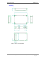
1
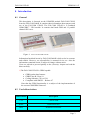
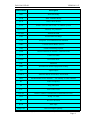
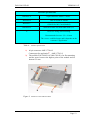
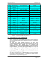
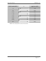
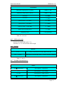
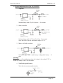
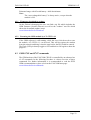
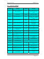
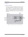
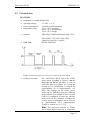
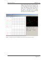
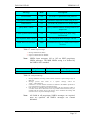
This document is available at HTTP://WWW.FALCOM.DE FALCOM C2D-SI User Manual Version 1.07 FALCOM C2D-SI VERSION 1.07 Contents 0 INTRODUCTION ..............................................................3 0.1 0.2 0.3 GENERAL ........................................................................................................................................ 3 USED ABBREVIATIONS .................................................................................................................... 3 RELATED DOCUMENTS.................................................................................................................... 5 1 SECURITY .........................................................................6 1.1 1.2 1.3 1.4 1.5 1.6 1.7 1.8 1.9 1.10 1.11 1.12 1.13 GENERAL INFORMATION ................................................................................................................. 6 EXPOSURE TO RF ENERGY .............................................................................................................. 6 EFFICIENT MODEM OPERATION ....................................................................................................... 6 ANTENNA CARE AND REPLACEMENT .............................................................................................. 7 DRIVING ......................................................................................................................................... 7 ELECTRONIC DEVICES ..................................................................................................................... 7 VEHICLE ELECTRONIC EQUIPMENT ................................................................................................. 7 MEDICAL ELECTRONIC EQUIPMENT ................................................................................................ 7 AIRCRAFT ....................................................................................................................................... 7 CHILDREN....................................................................................................................................... 8 BLASTING AREAS ............................................................................................................................ 8 POTENTIALLY EXPLOSIVE ATMOSPHERES ....................................................................................... 8 NON-IONISING RADIATION .............................................................................................................. 8 2 SAFETY STANDARDS .....................................................9 3 TECHNICAL DATA........................................................10 3.1 3.1.1 PIN CONFIGURATION OF THE 60 PIN CONNECTOR .......................................................................... 13 Determining the External Equipment Type ................................................................................. 15 4 GSM MODEM..................................................................17 4.1 4.1.1 4.1.2 4.1.3 4.1.4 4.1.5 4.1.6 4.1.7 4.2 4.2.1 4.2.2 4.3 4.3.1 4.3.2 GENERAL ...................................................................................................................................... 17 GSM capability............................................................................................................................ 17 GPRS capability........................................................................................................................... 17 GSM data services ....................................................................................................................... 17 RF characteristics......................................................................................................................... 17 SIM card reader ........................................................................................................................... 18 RS 232 ......................................................................................................................................... 18 Possible external devices ............................................................................................................. 18 SPECIAL FUNCTIONALITY PINS ...................................................................................................... 19 Firmware download procedure .................................................................................................... 23 Resetting the GSM module by AT+CFUN=1,1 .......................................................................... 23 GSM 07.05 AND 07.07 COMMANDS ............................................................................................. 23 General AT commands ................................................................................................................ 24 SMS AT commands (GSM 07.05) .............................................................................................. 25 5 GPS CORE........................................................................26 5.1 5.2 5.3 5.3.1 5.4 5.4.1 5.4.2 5.4.3 5.4.4 5.5 5.5.1 5.5.2 RECEIVER ARCHITECTURE ............................................................................................................ 26 TECHNICAL DATA ......................................................................................................................... 27 TECHNICAL DESCRIPTION ............................................................................................................. 29 Technical specification ................................................................................................................ 29 HARDWARE INTERFACE ................................................................................................................ 30 Configuration and timing signals................................................................................................. 30 Serial communication signals ...................................................................................................... 30 DC input signals .......................................................................................................................... 31 General purpose input/output (Pin 51, 53, 54 and 56) ................................................................. 31 SOFTWARE INTERFACE ................................................................................................................. 31 SiRF binary data message............................................................................................................ 31 NMEA data message ................................................................................................................... 34 This document is a property of FALCOM GmbH and may not be copied or circulated without permission Page 1 FALCOM C2D-SI VERSION 1.07 6 HOUSING .........................................................................36 7 GSM/GPS EVALUATION KIT......................................37 8 EMC AND ESD REQUIREMENTS...............................39 9 CE CONFORMITY .........................................................40 Version history Version number Author Changes 1.00 Sameh Awad Initial version 1.01 S. Mohamad - Fixing points (holes) described - Counterpart for the 60 pin connector added 1.02 F. Beqiri - Housing, AT-Commands, Temperature limits, Pin configuration. 1.03 F. Beqiri - Pictures of C2D-SI module changed Description of pin 15 corrected. 1.04 F. Beqiri - Hint in Trickle Power Mode added 1.05 F. Beqiri - Description of pin 15 corrected. 1.06 F. Beqiri - Description of pin 18 (VCCRTC) backup battery power completed. Table 3 power consumption for C2DSI updated. Table 4 power consumption for C2DSI-G10 added. Power consumption of GPS receiver updated. Determination for DCE-DTE connection (Chapter 3.1.1) added. Based on the DCE-DTE connection the name of RX and TX (from GSM core) signals in the table 7 updated. The name of RxA, TxA and RxB, TxB (from GPS core) updated, too. Mechanical dimensions of module updated. - 1.07 F. Beqiri - - This document is a property of FALCOM GmbH and may not be copied or circulated without permission Page 2 FALCOM C2D-SI VERSION 1.07 0 Introduction 0.1 General This description is focussed on the GSM/GPS module FALCOM C2D-SI from the FALCOM GmbH. It contains short information about purpose and use of the FALCOM C2D-SI. The FALCOM C2D-SI is a combined GSM/GPRS1) / GPS module. It contains dual band GSM and 12 parallel channel GPS cores. Figure 1: Views of FALCOM C2D-SI Information furnished herein by FALCOM GmbH is believed to be accurate and reliable. However, no responsibility is assumed for its use. Also the information contained herein is subject to change without notice. Users are advised to proceed quickly to the „Security“ chapter and read the hints carefully. 1) The FALCOM C2D-SI is GPRS capable. GPRS packet data features: GPRS Class B, Class 10 Coding Schemes: CS1 to CS4 Compliant with SMG32 – Release 97 Note that the GPRS functionality is a subject of the implementation of the current GSM/GPRS firmware. 0.2 Used abbreviations Abbreviation Description CTS Clear to send DGPS Differential GPS DOP Dilution of Precision This document is a property of FALCOM GmbH and may not be copied or circulated without permission Page 3 FALCOM C2D-SI VERSION 1.07 Abbreviation Description DSR Data Set Ready DTR Data Terminal Ready DCD Data Carrier Detect ECEF Earth-Centered Earth-Fixed Co-ordinate system EEPROM Memory for parameter EGSM Enhanced GSM ESD Electrostatic Discharge ETS European Telecommunication Standard GPRS General Packet Radio Service GPS Global Positioning System GSM Global Standard for Mobile Communications GGA GPS Fixed Data HDOP Horizontal DOP HW Hardware IMEI International Mobile Equipment Identity I/O Input/Output NMEA National Marine Electronics Association PRN Pseudorandom Noise Number – The Identity of GPS satellites RF Radio Frequency RI Ring Indication RTC Real Time Clock RTCM Radio Technical Commission for Maritime Services RTS Ready To Send Rx Receive direction RXD Data input RXQUAL Received Signal Quality This document is a property of FALCOM GmbH and may not be copied or circulated without permission Page 4 FALCOM C2D-SI VERSION 1.07 Abbreviation Description SIM Subscriber Identification Module SMS Short Message Service SRAM Static Random Access Memory SW Software TA Terminal Adapter TE Terminal Equipment TP Transmit Protocol TTFF Time to First Fix Tx Transmit direction TXD Data output SA Selective Availability WAAS Wide Area Augmentation System MSK Minimum Shift Keying Table 1: Used abbreviations 0.3 Related documents 1. ETSI GSM 07.05:“Use of Data Terminal Equipment–Data Circuit terminating Equipment interface for Short Message Service and Cell Broadcast Service” 2. ETSI GSM 07.07“AT command set for GSM Mobile Equipment” 3. ITU-T V.25ter“Serial asynchronous automatic dialling and control” 4. SiRF binary and NMEA protocol specification; www.falcom.de/Service/Manuals 5. “AT commands interface for FALCOM A2D, A2D-JP, A2D-SI, C2D, C2D-SI and A3D- Series”. www.falcom.de/Service/Manuals This document is a property of FALCOM GmbH and may not be copied or circulated without permission Page 5 FALCOM C2D-SI VERSION 1.07 1 Security IMPORTANT FOR THE EFFICIENT AND SAFE OPERATION OF YOUR GSM-MODEM, READ THIS INFORMATION BEFORE USE! Your cellular engine FALCOM C2D-SI is one of the most exciting and innovative electronic products ever developed. With it you can stay in contact with your office, your home, emergency services and others, wherever service is provided. This chapter contains important information for the safe and reliable use of the FALCOM C2D-SI. Please read this chapter carefully before starting to use the cellular engine FALCOM C2D-SI. 1.1 General information Your FALCOM C2D-SI modem utilises the GSM/GPRS standard for cellular technology. GSM is a newer radio frequency („RF“) technology than the current FM technology that has been used for radio communications for decades. The GSM standard has been established for use in the European community and elsewhere. Your modem is actually a low power radio transmitter and receiver. It sends out and receives radio frequency energy. When you use your modem, the cellular system handling your calls controls both the radio frequency and the power level of your cellular modem. 1.2 Exposure to RF energy There has been some public concern about possible health effects of using GSM modem. Although research on health effects from RF energy has focused for many years on the current RF technology, scientists have begun research regarding newer radio technologies, such as GSM. After existing research had been reviewed, and after compliance to all applicable safety standards had been tested, it has been concluded that the product is fit for use. If you are concerned about exposure to RF energy there are things you can do to minimise exposure. Obviously, limiting the duration of your calls will reduce your exposure to RF energy. In addition, you can reduce RF exposure by operating your cellular modem efficiently by following the guidelines below. 1.3 Efficient modem operation In order to operate your modem at the lowest power level, consistent with satisfactory call quality please take note of the following hints. If your modem has an extendible antenna, extend it fully. Some models allow you to place a call with the antenna retracted. However your modem operates more efficiently with the antenna fully extended. Do not hold the antenna when the modem is „IN USE“. Holding the antenna affects call quality and may cause the modem to operate at a higher power level than needed. This document is a property of FALCOM GmbH and may not be copied or circulated without permission Page 6 FALCOM C2D-SI VERSION 1.07 1.4 Antenna care and replacement Do not use the modem with a damaged antenna. If a damaged antenna comes into contact with the skin, a minor burn may result. Replace a damaged antenna immediately. Consult your manual to see if you may change the antenna yourself. If so, use only a manufacturer-approved antenna. Otherwise, have your antenna repaired by a qualified technician. Use only the supplied or approved antenna. Unauthorised antennas, modifications or attachments could damage the modem and may contravene local RF emission regulations or invalidate type approval. 1.5 Driving Check the laws and regulations on the use of cellular devices in the area where you drive. Always obey them. Also, when using your modem while driving, please pay full attention to driving, pull off the road and park before making or answering a call if driving conditions so require. When applications are prepared for mobile use they should fulfil road-safety instructions of the current law! 1.6 Electronic devices Most electronic equipment, for example in hospitals and motor vehicles is shielded from RF energy. However RF energy may affect some malfunctioning or improperly shielded electronic equipment. 1.7 Vehicle electronic equipment Check your vehicle manufacturer’s representative to determine if any on board electronic equipment is adequately shielded from RF energy. 1.8 Medical electronic equipment Consult the manufacturer of any personal medical devices (such as pacemakers, hearing aids, etc.) to determine if they are adequately shielded from external RF energy. Turn your FALCOM C2D-SI modem OFF in health care facilities when any regulations posted in the area instruct you to do so. Hospitals or health care facilities may be using RF monitoring equipment. 1.9 Aircraft Turn your FALCOM C2D-SI OFF before boarding any aircraft. Use it on the ground only with crew permission. Do not use it in the air. To prevent possible interference with aircraft systems, Federal Aviation Administration (FAA) regulations require you to have permission from a crew member to use your modem while the plane is on the ground. To prevent interference with cellular systems, local RF regulations prohibit using your modem whilst airborne. This document is a property of FALCOM GmbH and may not be copied or circulated without permission Page 7 FALCOM C2D-SI VERSION 1.07 1.10 Children Do not allow children to play with your FALCOM C2D-SI modem. It is not a toy. Children could hurt themselves or others (by poking themselves or others in the eye with the antenna, for example). Children could damage the modem or make calls that increase your modem bills. 1.11 Blasting areas To avoid interfering with blasting operations, turn your unit OFF when in a “blasting area” or in areas posted: „turn off two-way radio“. Construction crew often use remote control RF devices to set off explosives. 1.12 Potentially explosive atmospheres Turn your modem FALCOM C2D-SI OFF when in any area with a potentially explosive atmosphere. It is rare, but your modem or its accessories could generate sparks. Sparks in such areas could cause an explosion or fire resulting in bodily injury or even death. Areas with a potentially explosive atmosphere are often, but not always, clearly marked. They include fuelling areas such as petrol stations; below decks on boats; fuel or chemical transfer or storage facilities; and areas where the air contains chemicals or particles, such as grain, dust or metal powders. Do not transport or store flammable gas, liquid or explosives, in the compartment of your vehicle which contains your modem or accessories. Before using your modem in a vehicle powered by liquefied petroleum gas (such as propane or butane) ensure that the vehicle complies with the relevant fire and safety regulations of the country in which the vehicle is to be used. 1.13 Non-ionising radiation As with other mobile radio transmitting equipment users are advised that for satisfactory operation and for the safety of personnel, it is recommended that no part of the human body be allowed to come too close to the antenna during operation of the equipment. The radio equipment shall be connected to the antenna via a non-radiating 50 Ohm coaxial cable. The antenna shall be mounted in such a position that no part of the human body will normally rest close to any part of the antenna. It is also recommended to use the equipment not close to medical devices as for example hearing aids and pacemakers. This document is a property of FALCOM GmbH and may not be copied or circulated without permission Page 8 FALCOM C2D-SI VERSION 1.07 2 Safety standards This GSM modem complies with all applicable RF safety standards. The embedded GMS modem meets the safety standards for RF receivers and the standards and recommendations for the protection of public exposure to RF electromagnetic energy established by government bodies and professional organizations, such as directives of the European Community, Directorate General V in matters of radio frequency electromagnetic energy. This document is a property of FALCOM GmbH and may not be copied or circulated without permission Page 9 FALCOM C2D-SI VERSION 1.07 3 Technical data General specifications Dimensions 64 mm x 41.5 mm x 12.5mm (B x W x H) (for more details see chapter 6 Housing) Weight 43g Table 2: General specifications C2D-SI-900/1800 power consumption GPS on VC3 3.3 V DC ± 5 % /GSM off Max. 65 mA continuous mode VC5 5.0 V DC ± 5 % Average current (in mA at 5 V nominal): GPS off /GSM on 900 1800 MHz GSM band 14 14 mA in idle mode (base station sends at -85 dBm) 167 135 mA in transmit mode at power level 7/3 220 189 mA in transmit mode at power level 5/0 Serial interface is applied and working. Table 3: Power supply and current consumption (for C2D-SI) at 5 V DC This document is a property of FALCOM GmbH and may not be copied or circulated without permission Page 10 FALCOM C2D-SI VERSION 1.07 C2D-SI-900/1800-G10 power consumption GPS on VC3 3.3 V DC ± 5 % /GSM off Max. 65 mA continuous mode VC5 5.0 V DC ± 5 % Average current (in mA at 5 V nominal): GPS Off /GSM on GPS off /GPRS on 900 1800 MHz GSM band 16 16 mA in idle mode (base station sends at -85 dBm) 185 135 mA in transmit mode at power level 7/3 237 183 mA in transmit mode at power level 5/0 mA in transmit/receive mode at maximum power level 5 (3 x downstream +2 x upstream using Coding Scheme 4 (CS-4)) 441 Serial interface is applied and working. Table 4: Power supply and current consumption (for C2D-SI-G10) at 5 V DC Temperature limits Operation/Full GSM specification compliant -20°C to +55°C Transportation -40°C to +70°C Storage -30°C to +85°C Table 5: Temperature limits This document is a property of FALCOM GmbH and may not be copied or circulated without permission Page 11 FALCOM C2D-SI VERSION 1.07 Interface specifications Interface A 60pin connector AMP 177984-21) Interface B GPS 50 Ω, MCX female Interface C GSM 50 Ω, MC-Card (Radiall) Interface D SIM card reader for small SIM cards (3V) E Holes for fixing after mounting Recommended screws: 2,2 x 16 mm The screw could be longer and it depends on the customer’s application Table 6: Interface specifications 1) 60 pin connector AMP 177984-2 Counterpart for application2): AMP 177983-2 2) The module FALCOM FALCOM C2D-SI is for flat mounting and the space between the highest point of the module and its bottom is 2 mm. Figure 2: Interfaces of the C2D-SI modem This document is a property of FALCOM GmbH and may not be copied or circulated without permission Page 12 FALCOM C2D-SI VERSION 1.07 3.1 Pin configuration of the 60 pin connector PIN GSM modem DESCRIPTION LEVEL 1 MIC P2 a Microphone 2 positive differential input 2 MIC N2 a Microphone 2 negative differential input 3 SPK P2 a Speaker 2 positive differential output 4 SPK N2 a Speaker 2 negative differential output 5 DTR0 Data Terminal Ready CMOS 2,8 V input 6 CTS0 Clear To Send CMOS 2,8 V output 7 DSR0 Data Set Ready CMOS 2,8 V output 8 RTS0 Ready To Send CMOS 2,8 V input 9 RI0 Ring Indicator CMOS 2,8 V output 10 DCD0 Data Carrier Detect CMOS 2,8 V output 11 SOFT ON Turn phone on CMOS 2,8 V input 12 RING PWM Ringer Interface CMOS 2,8 V output 13 RX Receive Data CMOS 2,8 V output 14 TX Transmit Data CMOS 2,8 V input 15 Reserved Please do not connect ! 16 RESET GSM Reset-Active Low SCHMITT-Trigger 17 MIC N1 a Microphone 1 negative differential input 18 VCCRTC RTC back-up battery supply +2 .. 2.75 V input 19 SPK N1 a Speaker 1 negative differential output 20 MIC P1 a Microphone 1 positive differential input 22 SPK P1 a Speaker 1 positive differential output 23 VC5 Power supply 5 V DC 24 VC5 Power supply 5 V DC This document is a property of FALCOM GmbH and may not be copied or circulated without permission Page 13 FALCOM C2D-SI VERSION 1.07 PIN GSM modem DESCRIPTION LEVEL 25 VC5 Power supply 5 V DC 26 VC5 Power supply 5 V DC 27 GPIO1 (GSM) General purpose CMOS 2,8 V inp./out. 28 VC5 Power supply 5 V DC 30 EN Internal Power enable CMOS 2,8 V input 31 GROUND - - 32 GROUND - - 33 GROUND - - 34 GROUND - - 35 SIMPREK SIM present for external card CMOS 2,8 V input 36 Reserved Please do not connect! 37 SIMDATA SIM Data CMOS 2,8 V inp./out. 38 SIMVCC SIM Card power supply 3 V DC output 39 SIMRST SIM Reset output 40 SIMCLK SIM Clock output Table 7: Pin configuration AMP 177984-2 PIN GPS receiver DESCRIPTION LEVEL 21 GPIO15 Reserved CMOS 3,3 V inp./out. 29 GPIO10 Reserved CMOS 3,3 V inp./out. 41 TMARK 1 PPS Time Mark Output CMOS 3,3 V output 42 BOOTSELECT For firmware update active high 43 GROUND - - 44 GROUND - - 45 SDI2 Serial 2 Data Input CMOS 3,3 V input 46 GROUND - - This document is a property of FALCOM GmbH and may not be copied or circulated without permission Page 14 FALCOM C2D-SI VERSION 1.07 PIN GPS receiver DESCRIPTION LEVEL 47 GROUND - - 48 SDO2 Serial 2 Data Output CMOS 3,3 V output 49 SDO1 Serial 1 Data Output CMOS 3,3 V output 50 SDI1 Serial 1 Data Input CMOS 3,3 V input 51 GPIO6 Reserved CMOS 3,3 V input/output 52 GROUND - - 53 GPIO5 Reserved CMOS 3,3 V inp./out. 54 GPIO A Reserved CMOS 3,3 V inp./out. 55 M-RST Master Reset Input active low 56 GPIO7 Reserved CMOS 3,3 V inp./out. 57 VBATT_RTC Battery Backup Input 3 V DC 58 3,3 V DC Primary DC Power 3,3 V DC 59 Reserved Reserved for Preamplifier Power.(see page 27) (3,3 V DC - 6 V DC) 60 3,3V DC Primary DC Power 3,3 V DC Table 8: Pin configuration AMP 177984-2, GPS receiver 3.1.1 Determining the External Equipment Type Before you connect the C2D-SI module (DCE unit) to external equipment, you need to determine if the external hardware serial ports are configured as DTE or DCE. The terms DTE (Data Terminal Equipment) and DCE (Data Communications Equipment) are typically used to describe serial ports on devices. Computers (PCs) generally use DTE connectors and communication devices such as modems and DSU/CSU devices generally use DCE connectors. As a general rule, DTE ports connect to DCE ports via straight through pinned cables. In other words, a DTE port never connects directly to another DTE port. Similarly, a DCE port never connects directly to another DCE port. The signalling definitions were written from the perspective of the DTE device; therefore, a Receive Data signal becomes an input to DTE but an output from DCE. The C2D-SI is designed for use as a DCE unit. Based on the aforementioned conventions for DCE-DTE connections it communicates with the customer application (DTE) using the following signals: This document is a property of FALCOM GmbH and may not be copied or circulated without permission Page 15 FALCOM C2D-SI VERSION 1.07 GSM Terminal (DCE) to Application (DTE) TX ◄----------------------- TXD RX -----------------------► RXD RTS0 ◄----------------------- RTS CTS0 -----------------------► CTS DTR0 ◄----------------------- DTR DSR0 -----------------------► DSR DCD0 -----------------------► DCD RI0 -----------------------► RING Table 11: The signaling definitions between DTE and DCE. This document is a property of FALCOM GmbH and may not be copied or circulated without permission Page 16 FALCOM C2D-SI VERSION 1.07 4 GSM modem 4.1 General 4.1.1 GSM capability E-GSM and DCS (GSM ETSI Phase I and II) 4.1.2 GPRS capability The FALCOM C2D-SI is GPRS class B, class 10 capable. It supports PBCCH/PCCCH; coding schemes: CS1 to CS4 and it is compliant with SMG32 – Release 97. Note that the GPRS functionality is a subject of the implementation of the current GSM/GPRS firmware. 4.1.3 GSM data services 300....14400 BPS, asynchronous, transparent and non-transparent (V.21, V.22, V.23, V.22bis, V.26ter, V.32, V.34, V.110) 4.1.4 RF characteristics Receiver EGSM Sensitivity < -104 dBm DCS Sensitivity < -100 dBm Selectivity @ 200 kHz > +9 dBc Selectivity @ 400 kHz > +41 dBc Dynamic range 62 dB Intermodulation > -43 dBm Co-channel rejection ≥ 9 dBc Table 9: Receiver Transmitter Maximum output power (EGSM) 33 dBm ± 2 dB Maximum output power (DCS) 30 dBm ± 2 dB This document is a property of FALCOM GmbH and may not be copied or circulated without permission Page 17 FALCOM C2D-SI VERSION 1.07 Transmitter Minimum output power (EGSM) 5 dBm ± 5 dB Minimum output power (DCS) 0 dBm ± 5 dB H2 level ≤ 30 dBm H3 level ≤ 30 dBm Noise in 925....935 MHz ≤ 67 dBm Noise in 935....960 MHz ≤ 79 dBm Noise in 1805....1880 MHz ≤ 71 dBm Phase error at peak power < 5° RMS Frequency error ± 0.1 ppm max Table 10: Transmitter 4.1.5 SIM card reader Internal, for small SIM cards (3 V) External, 10...15 cm maximum cable length 4.1.6 RS 232 RS 232 2.8 V RX, TX, RTS,CTS, DTR, DSR, DCD, RI 300....115200 Baud rates for serial link (2400...19200 with auto-bauding) Table 11: RS 232 4.1.7 Possible external devices Audio 2 KΩ differential Microphone 1 impedance 2V Microphone 1 bias voltage 0,5 mA Microphone 1 input current 2 KΩ differential Microphone 2 impedance This document is a property of FALCOM GmbH and may not be copied or circulated without permission Page 18 FALCOM C2D-SI VERSION 1.07 Audio 2V Microphone 2 bias voltage 0,5 mA Microphone 2 input current > 50 Ω (<1nF) Speaker 1 impedance > 50 Ω (<1nF) Speaker 2 impedance Table 12: Audio 4.2 Special functionality pins Table 7 and table 8 show the pin-configuration of the AMP 177984-2. In these tables CMOS means 2.8 V. You may use a 3 V or 3.3 V CMOS level logic (never 5 V) on the 2.8 V I/O’s. However, it is required to add serial resistance on all the lines you will use (typical value: from 4.7 to 10 KΩ). There are a few pins needed for the operation of the module. The handling of pins is described as follows. Pin 30 (EN) This signal is an input of the internal voltage regulator. Pull to LOW to switch the voltage regulator off (for minimum current consumption). Pull to HIGH or leave the signal open if EN is not used. Pin 27 (GPIO 1 Æ Flash_LED) This signal can be used to show the current status of the module: If GPIO 1 is LOW then the module is off. If it is continuously HIGH then module is on, but not registered into a network. If GPIO 1 is flashing in a 2sec period then the module is on and registered into a network. If it flashes in a 1sec period then the module is on and a call is in progress (incoming or outgoing). GPIO 1 can be an input into a controller (here it needs to be driven by an open collector circuit) or used together with a LED (see figure 3). This document is a property of FALCOM GmbH and may not be copied or circulated without permission Page 19 FALCOM C2D-SI VERSION 1.07 Figure 3: PIN 27 Pin 35 (SIMPREK) This signal needs to be driven by an open collector circuit. It is used by the module firmware to detect a SIM card exchange when the module is online. A high to low transition means SIM card is inserted and the module will be able to accept the AT+CPIN command. A low to high transition means SIM card has been removed, the module will de-register from the network an show the unsolicited error code CME ERROR: 10. Figure 4: Sample application for SIMPREK Pin 16 (RESET GSM) This signal needs to be driven by an external open collector circuit. • To issue a hardware reset pull the signal to LOW for a minimum of 100ms. • Pull the signal to HIGH or leave it open for normal operation. This document is a property of FALCOM GmbH and may not be copied or circulated without permission Page 20 FALCOM C2D-SI VERSION 1.07 Pin 11 (SOFT_ON) This signal needs to be driven by an external open collector circuit. For switching the module on (external power must be connected!) set the SOFT_ON signal to HIGH for approx. 3sec. The signal can be left HIGH until module shall be switched off. For switching the module off the commands AT+CPOF or AT+CFUN=0 have to be issued. If SOFT_ON is HIGH then only the RF part of the module is off, but the AT command set is still working (AT+CFUN=1 can be used to wake up the RF part again) the Flash_LED stays HIGH. - If SOFT_ON is LOW then the complete GSM engine goes OFF the Flash-LED goes LOW. Some small power consumption will be still there, use the EN pin to avoid that. It is not recommended to switch the module on and off by means of the power supply (e. g. by tying the SOFT_ON constantly to HIGH). The module will so have no possibility to de-register correctly from the network and this will cause problems at the next attempt to register. Pin 18 (VCCRTC) This pin is used as a back-up power supply for the internal Real Time Clock of GSM/GPRS engine. The RTC is supported by the C2D-SI module when powered on but a back-up power supply is needed to save date and time when the module is switched off (see AT+CCLK to set the date and time). If the RTC is not used, this pin can be left open. Name VCCRTC Pin number 18 I/O I/O I/O type Supply Description RTC Back-up supply Operating condition Parameter Input voltage Input current Input current Output voltage Output current Condition Vcc = 0V; t° = 25°C VCCRTC = 2.5V Vcc=0V; t° = -20°C /55°C VCCRTC = 2.5V Min 2 Max 2.75 Unit V 2 3 µA 10 µA 2.75 2 V mA 2.4 This document is a property of FALCOM GmbH and may not be copied or circulated without permission Page 21 FALCOM C2D-SI VERSION 1.07 Typical implementation of pin 18 (VCCRTC) 1. Capacitor Estimated range with 470 µF Capacitor : ~30 seconds. 2. Super capacitor Estimated range with 0.47 Farad Gold Cap : 2 hours min. Note : the Gold Capacitor maximum voltage is 2.5 V. 3. Battery cell with regulator Estimated range with 2 mAh battery rechargeable battery : ~3 days. Warning : Before battery cell assembly insure that cell voltage is lower than 2,75V to avoid any damage to the C2D-SI module. 4. Non Rechargeable battery This is the less recommended solution This document is a property of FALCOM GmbH and may not be copied or circulated without permission Page 22 FALCOM C2D-SI VERSION 1.07 Estimated range with 85 mAh battery : 4000 h minimum Note : The “non rechargeable battery” is always active, except when the module is ON. 4.2.1 Firmware download procedure On the Falcom’s homepage the user can find a zip file which includes the GSM firmware (Loader software) as well as the “readme” text file which shows the download (update) steps. www.falcom.de/Service/firmware 4.2.2 Resetting the GSM module by AT+CFUN=1,1 If the GSM software is still running, while the user feels the need to reset the module, AT+CFUN=1,1 can be used. This will de-register the modem from the network and bring it into the state before the PIN could be entered. The Flash_LED pin shortly toggle to OFF and back to ON again to show the progress. 4.3 GSM 07.05 and 07.07 commands The GSM modem of the FALCOM C2D-SI is controlled by an advanced set of AT commands. In the following list there is a short overview of these commands. For further information it is recommended to read the ETSI GSM recommendation or have a look at the FALCOM homepage : www.falcom.de/Service/Manuals This document is a property of FALCOM GmbH and may not be copied or circulated without permission Page 23 FALCOM C2D-SI VERSION 1.07 4.3.1 General AT commands Command Meaning Command Meaning +++ Switch to command mode when connected AT&C1 DCD matches state of the remote modem’s data carrier ATA Answer call AT&D0 Ignore DTR signal ATDx Dial data number „x” AT&D1 At DTR-> OFF: Switches from data to command mode ATDx; Dial voice number „x” AT&D2 At DTR-> OFF: Clear down the call ATE0 Disable command echo AT&W Store current configuration ATE1 Enable command echo T+IPR Select the modem’s data rate ATH Disconnect existing connection AT+IFC Select the modem’s local flow control setting ATO Return to data mode AT+VGR Tune the receive gain ATS0=n Go off-hook after n-th ringing signal (n = „1”- „5”) AT+VGT Tune the transmit gain ATS0=0 No automatic answering of calls AT+VTD Define DTMF tone duration ATZ Load stored profile AT+VTS Send DTMF tone AT&C0 DCD always ON AT+CBST Select the bearer type AT+CPIN Enter PIN and query blocks AT+CCFC Control the call forwarding supplementary service AT+CPWD Change PIN or the supplementary password AT+CCWA Control the call waiting supplementary service AT+CSQ Display signal quality information AT+CR Select connection service report AT+CFUN Select the functionality level in the modem This document is a property of FALCOM GmbH and may not be copied or circulated without permission Page 24 FALCOM C2D-SI VERSION 1.07 Command Meaning Command Meaning AT+CGMI Display manufacturer ID AT+CRC Select call service report AT+CGMM Display model ID ATCLIP Calling line identification presentation AT+CGMR Display version of GSM module AT+CLIR Control the calling line identification presentation AT+CGSN Display serial number (IMEI) AT+COLP Control the connected line identification presentation AT+CREG Display network registration status AT+CMEE Report mobile equipment errors AT+COPS AT+CEER Extend error report Commands relating to network operator selection Table 13: General AT commands 4.3.2 SMS AT commands (GSM 07.05) Command Meaning Command Meaning AT+CSCA Service centre address AT+CMGR Read message AT+CSCS Select TE character set AT+CMGS Send message AT+CSDH Show test mode parameter AT+CMGD Delete message AT+CSMP Select text mode parameter AT+CMGL List message AT+CSMS Select message service AT+SNMI New message indication AT+CPMS Preferred message storage AT+CSAS Save SMS settings AT+CMGF Text mode / PDU Mode AT+CRES Restore SMS settings Table 14: SMS AT commands This document is a property of FALCOM GmbH and may not be copied or circulated without permission Page 25 FALCOM C2D-SI VERSION 1.07 5 GPS core 5.1 Receiver architecture The GPS receiver in the FALCOM C2D-SI from FALCOM is a new GPS receiver product that features the SiRFstarII chipset. This complete 12 channel, WAAS-enabled GPS receiver provides a vastly superior position accuracy performance in a much smaller package. The SiRFstarII architecture builds on the high-performance SiRFstarI core, adding an acquisition accelerator, differential GPS processor, multipath mitigation hardware and satellite-tracking engine. The receiver delivers major advancements in GPS performance, accuracy, integration, computing power and flexibility. Figure 5: Architecture of the GPS receiver core inside FALCOM C2D-SI This document is a property of FALCOM GmbH and may not be copied or circulated without permission Page 26 FALCOM C2D-SI VERSION 1.07 5.2 Technical data FEATURES Integrated 12 parallel channel GPS operating voltage: 3.3 VDC +/- 5 % power consumption: temperature range: 220 mW (continuous mode) -20 to +55°C operation -40 to +70°C transportation -25 to +70°C storage protocol: SDI1/SDO1: NMEA 4800 baud, Msg.: GLL, RXB/TXB: GGA, RMC, VTG, GSV, GSA, ZDA 8 data bits, no parity, 1 stop bit RTCM, 9600 baud Figure 6: Default settings for the trickle power mode of FALCOM C2D-SI trickle power mode: The FALCOM C2D-SI enters the trickle power mode according to figure 6 (800 ms OFF Time and 200 ms ON Time) as soon as valid GPS data are available. As a result the average power consumption is reduced by approximately 80 % (approximately 150 mW). The settings for the trickle power mode can be modified using the SiRFstar demo software. For example if the FALCOM C2D-SI is configured to enter the OnTime mode each 10s for a duration of 200ms the average power consumption can be reduced by approximately 95% (approximately 15mW, ca. 4,8mA at Vcc=3.3V). Hint: The power-on scenario in Trickle Power Mode differs from one in continuous This document is a property of FALCOM GmbH and may not be copied or circulated without permission Page 27 FALCOM C2D-SI VERSION 1.07 mode. If the module fails to acquire satellites within a given period of time (approx. 150 sec), the module goes into an extended sleep phase. The duration of this sleep phase is approx. 30 sec. After that, the module wakes up, make a reset and tries to acquire satellites. This procedure repeats itself until the GPS receiver can detect satellites. Figure 7: Example of using of the SiRFdemo (FALCOM C2D-SI in trickle power mode) This document is a property of FALCOM GmbH and may not be copied or circulated without permission Page 28 FALCOM C2D-SI VERSION 1.07 5.3 Technical description 5.3.1 Technical specification Electrical Characteristics 1. General Frequency C/A code Channels L1, 1575.42 MHz 1.023 MHz chip rate 12 2. Accuracy Position Velocity Time 3. DGPS Accuracy Position Velocity 4. Datum 10 meters CEP without SA 0.1 meters/second, without SA 1 microsecond synchronized to GPS time 1 to 5 meters, typical 0.05 meters/second, typical WGS-84 5. Acquisition Rate Snap start Hot start Warm start Cold start < 3 sec., average < 8 sec., average < 38 sec., average < 45 sec., average 6. Dynamic Conditions Altitude Velocity Acceleration Jerk 18,000 meters (60,000 feet) max. 515 meters/second (1000 knots) 4g, max. (g = 9,8m/s) 20 meters/second³, max. max. 7. DC Power Main power Continuous mode Backup battery power + 3.3 V DC +/- 5 % 65mA typical at 3.3 V DC typical +3V DC ± 0.25 V 8. Serial Port Electrical interface Protocol messages DGPS protocol Two full duplex serial communication, CMOS interfaces. SiRF binary and NMEA-0183, version 2.20 with a baud rate selection. SiRF binary position, velocity, altitude, status and control NMEA CGA, GLL, GSA, GSV, RMC and VTG. RTCM SC-104, version 2.00,type 1,5 and 9. This document is a property of FALCOM GmbH and may not be copied or circulated without permission Page 29 FALCOM C2D-SI VERSION 1.07 9. Time 1PPS Pulse (T-Mark) Level Pulse duration Time reference CMOS 100 ms At the pulse positive edge Measurements Aligned to GPS second, +/- microsecond 5.4 Hardware interface 5.4.1 Configuration and timing signals M-RST (Pin 55) This pin provides an active-low reset input to the board. It causes the board to reset and start searching for satellites. Reset is an optional input and, if not utilized, it may be left open. T-Mark (Pin 41) This pin provides 1 pulse per second output from the board, which is synchronized to within 1 microsecond of GPS time. The output is a CMOS level signal. This is not available in trickle power mode. Bootselect (Pin 42) This pin is setting high for programming the flash of the FALCOM C2D-SI (for instance updating to a new firmware for the GPS receiver in the FALCOM C2DSI). 5.4.2 Serial communication signals The board supports two full duplex serial channels. All four connections are at CMOS levels, all support variable baud rates and all can be controlled from the appropriate screens in SiRFdemo software. You can directly communicate with a PC serial port. SDI1 (Pin 50) This is the main receiving channel and is used to receive software commands to the board from SiRFdemo software or from user written software. SDI2 (Pin 45) This is the auxiliary receiving channel and is used to input differential corrections to the board to enable DGPS navigation. SDO1 (Pin 49) This is the main transmitting channel and is used to output navigation and measurement data to SiRFdemo or user written software. SDO2 (Pin 48) For user’s application. This document is a property of FALCOM GmbH and may not be copied or circulated without permission Page 30 FALCOM C2D-SI 5.4.3 VERSION 1.07 DC input signals VCC (Pin 58 and 60) This is the main DC power supply for 3,3 V powered board FALCOM C2D-SI. Connect both pins. VANT (Pin 59) This pin is reserved for an external DC power supply for an active antenna (e.g.: 5 V active antenna). With a change of the PCB assembling this pin can be activated. Default: The GPS core in the FALCOM C2D-SI has to be connected with active 3 V GPS antenna with max. current of 20mA. The antenna voltage is provided by the internal power management GND 5.4.4 GND provides the ground for the GPS core. (Pins 43, 44, 46, 47 and 52) Connect all GND pins. General purpose input/output (Pin 51, 53, 54 and 56) Several I/O’s of the CPU are connected to the hardware interface connector of the FALCOM C2D-SI. They are reserved for customer specific applications. 5.5 Software interface The GPS core in the FALCOM C2D-SI supports NMEA-0183 and SiRF binary protocols. A short description of these protocols are provided herein. For more detailed information please refer to the SiRFstarII message set specification available in the section “service/manuals” of the FALCOM homepage. 5.5.1 SiRF binary data message Hex ASCII Name Description 0 x 02 2 Measured Navigation Data Position, velocity and time 0 x 03 3 True Tracker Data Not implemented 0 x 04 4 Measured Tracking Data Satellite and C/No information 0 x 05 5 Raw Track Data Not supported by SiRFstarII 0 x 06 6 SW Version Receiver software 0 x 07 7 Clock Status Current clock status This document is a property of FALCOM GmbH and may not be copied or circulated without permission Page 31 FALCOM C2D-SI VERSION 1.07 Hex ASCII Name Description 0 x 08 8 50 BPS Subframe Data Standard ICD format 0 x 09 9 Throughput Navigation complete data 0 x 0A 10 Error ID Error coding for message failure 0 x 0B 11 Command Acknowledgment Successful request 0 x 0C 12 Command Nacknowledgment Unsuccessful request 0 x 0D 13 Visible List Auto Output 0 x 0E 14 Almanac Data Response to Poll 0 x 0F 15 Ephemeris Data Response to Poll 0 x 10 16 Test Mode 1 For use with SiRFtest (Test Mode 1) 0 x 11 17 Differential Corrections Received from DGPS broadcast 0 x 12 18 OkToSend CPU ON/OFF (Trickle Power) 0 x 13 19 Navigation Parameters Response to Poll 0 x 14 20 Test Mode 2 Additional test data (Test Mode 2) 0 x 1C 28 Nav. Lib. Measurement Data Measurement Data 0 x 1D 29 Nav. Lib. DGPS Data Differential GPS Data 0 x 1E 30 Nav. Lib. SV State Data Satellite State Data 0 x 1F 31 Nav. Lib. Initialization Data Initialization Data 0 x FF 255 Development Data Various status messages 0 x 55 85 Transmit Serial Message User definable message 0 x 80 128 Initialize Data Source Receiver initialization and associated parameters 0 x 81 129 Switch to NMEA Protocol Enable NMEA message, output rate and baud rate 0 x 82 130 Set Almanac (upload) Sends an existing almanac file to the receiver 0 x 84 132 Software Version (Poll) Polls for the loaded software version This document is a property of FALCOM GmbH and may not be copied or circulated without permission Page 32 FALCOM C2D-SI VERSION 1.07 Hex ASCII Name Description 0 x 85 133 DGPS Source Control DGPS correction source and beacon receiver information 0 x 86 134 Set Main Serial Port Baud rate, data bits, stop bits and parity 0 x 87 135 Switch Protocol Obsolete 0 x 88 136 Mode Control Navigation mode configuration 0 x 89 137 DOP Mask Control DOP mask selection and parameters 0 x 8A 138 DGPS Mode DGPS mode selection and timeout value 0 x 8B 139 Elevation Mask Elevation tracking and navigation masks 0 x 8C 140 Power Mask Power tracking and navigation masks 0 x 8D 141 Editing Residual Not implemented 0 x 8E 142 Steady-State Detection not used Not implemented 0 x 8F 143 Static Navigation Configuration for static operation 0 x 90 144 Poll Clock Status (Poll) Polls the clock status 0 x 91 145 Set DGPS Serial Port DGPS port baud rate, data bits, stop bits and parity 0 x 92 146 Poll Almanac Polls for almanac data 0 x 93 147 Poll Ephemeris Polls for ephemeris data 0 x 94 148 Flash Update On the fly software update 0 x 95 149 Set Ephemeris (upload) Sends an existing ephemeris to the receiver 0 x 96 150 Switch Operating Mode Test mode selection, SV ID and period 0 x 97 151 Set Trickle Power Parameters Push to fix mode, duty cycle and on time 0 x 98 152 Poll Navigation Parameters Polls for the current navigation parameters This document is a property of FALCOM GmbH and may not be copied or circulated without permission Page 33 FALCOM C2D-SI VERSION 1.07 Hex ASCII Name Description 0 x A5 165 Set UART Configuration Protocol selection, baud rate, data bits, stop bits and parity 0 x A6 166 Set Message Rate SiRF binary message output rate 0 x A7 167 Low Power Acquisition Parameters Low power configuration parameters 0 x B6 182 Set UART Configuration Obsolete Table 15: lists the message list for the SiRF output messages 5.5.2 NMEA data message The SiRFstarIIe evaluation receiver is capable of outputting data in the NMEA-0183 format as defined by the National Marine Electronics Association (NMEA), Standard for Interfacing Marine Electronic Devices, Version 2.20, January 1, 1997. See “Using the SiRFdemo Software” for instructions on using NMEA. NMEA output messages table 16 lists each of the NMEA output messages supported by the SiRFstarIIe evaluation receiver and a brief description. Option Description GGA Time, position and fix type data. GLL Latitude, longitude, UTC time of position fix and status. GSA GPS receiver operating mode, satellites used in the position solution and DOP values. GSV The number of GPS satellites in view satellite ID numbers, elevation, azimuth and SNR values. MSS Signal-to-noise ratio, signal strength, frequency and bit rate from a radio-beacon receiver. RMC Time, date, position, course and speed data. VTG Course and speed information relative to the ground. Table 16: NMEA Output Messages This document is a property of FALCOM GmbH and may not be copied or circulated without permission Page 34 FALCOM C2D-SI VERSION 1.07 Message MID1 Description SetSerialPort 100 Set PORT A parameters and protocol Navigation Initialization 101 Parameters required for start using X/Y/Z2 SetDGPSPort 102 Set PORT B parameters for DGPS input Query/Rate Control 103 Query standard NMEA message and/or set output rate LLANavigation Initialization 104 Parameters required for start using Lat/Lon/Alt3 Development Data On/Off 105 Development Data messages On/Off MSK Receiver Interface MSK Command message to a MSK radio-beacon receiver. Table 17: NMEA input messages 1. Message Identification (MID). 2. Input co-ordinates must be WGS84. 3. Input co-ordinates must be WGS84. Note: Start NMEA input messages 100 to 105 are SiRF proprietary NMEA messages. The MSK NMEA string is as defined by the NMEA 0183 standard. Payload Data2 Checksum *CKSUM3 End Sequence <CR> <LF>4 $ Table 18: Transport Message 1. 2. 3. 4. Note: Message Identifier consisting of three numeric characters. Input messages begin at MID 100. Message specific data. Refer to a specific message section for <data>...<data>definition. CKSUM is a two-hex character checksum as defined in the NMEA specification. Use of checksums is required on all input messages. Each message is terminated using Carriage Return (CR) Line Feed (LF) which is \r\n which is hex 0D 0A. Because \r\n are not printable ASCII characters, they are omitted from the example strings, but must be sent to terminate the message and cause the receiver to process that input message. All fields in all proprietary NMEA messages are required, none are optional. All NMEA messages are comma delimited. This document is a property of FALCOM GmbH and may not be copied or circulated without permission Page 35 FALCOM C2D-SI VERSION 1.07 12.1 6 Housing 36.1 ±0.1 39. 3 ±0.1 62 ±0.1 58.8 ±0.1 6.0 ±0.1 3,5 ±0.1 9.1 ±0.1 21,1 ±0.1 2,5 ±0.1 31.0 ±0.1 6.0 ±0.1 4,1 ±0.1 Figure 9: Housing of FALCOM C2D-SI This document is a property of FALCOM GmbH and may not be copied or circulated without permission Page 36 FALCOM C2D-SI VERSION 1.07 7 GSM/GPS evaluation kit The quickest way to get first results with the embedded GSM/GPS module is the activation by the GSM/GPS evaluation kit by means of a terminal program. The FALCOM GSM/GPS EVAL-KIT provides design engineers with all necessary hard- and software information for the creation of embedded applications based on FALCOM embedded modules. It saves design, time and reduces “Time-to-Market” period. Figure 10: The FALCOM GSM/GPS evaluation board (EVAL-KIT) Figure 10 shows the GSM/GPS evaluation kit in complete packaging, i. e. GSM/GPS evaluation board power supply FRIWO type FW 3299 (12V DC/580 mA) GPS antenna ANT-006 RS232 combined cable (GSM/GPS A/GPS B) headset with RJ45 plug GSM antenna ANT-001 CD with: “SiRF messages” Input/Output messages for FALCOM GPSreceivers with SiRFStarIIe-chip-set. “SiRF demo” software description “SiRF demo 3.36.exe” software A2D test software evaluation board user manual schematics of the evaluation platform (power supply, external SIM card, serial interface) This document is a property of FALCOM GmbH and may not be copied or circulated without permission Page 37 FALCOM C2D-SI VERSION 1.07 The evaluation kit transfers data from GSM module and GPS receiver to two separate RS232 interfaces. For voice communication by the GSM module there is a headset available. The data of both modules can be processed by your PC at the same time. Thus the evaluation kit offers an excellent possibility for development and testing (trials) of your own application on the base of the embedded GSM/GPS modules FALCOM C2D-SI. This document is a property of FALCOM GmbH and may not be copied or circulated without permission Page 38 FALCOM C2D-SI 8 VERSION 1.07 EMC and ESD requirements The ETS 300342-1 standard applies to the FALCOM C2D-SI with regard to EMC and ESD requirements. Additional requirements in relation to EMC/ESD: If the FALCOM C2D-SI is being used in cars, the requirements regarding power supply as defined in section 9.6 of the ETS 300342-1 (6/97) standard must be fulfilled. The connecting cable between the chip card reader and the socket on the FALCOM C2D-SI must be shielded in compliance with EMC requirements. When using the FALCOM C2D-SI cellular engine with individual handsfree equipment, noise interference may occur. The FALCOM C2D-SI cellular engine must be connected directly to the ground of the base device. Note: The device should only be handled in compliance with ESD regulations (grounded, ESD chain, trained personnel). This document is a property of FALCOM GmbH and may not be copied or circulated without permission Page 39 FALCOM C2D-SI VERSION 1.07 9 CE conformity The FALCOM C2D-SI bears the CE symbol. This symbol represents the manufacturer’s declaration that the design and implementation of the FALCOM C2D-SI meets the currently valid versions of the following EU guidelines: 89/336/EC 73/23/EC 91/263/EC (EMC guideline) (Low voltage guideline) (Telecommunication devices guideline) Standards: ETS 300342-1 EN 60950 TBR 19 TBR 20 EMC: Safety: GSM network: This document is a property of FALCOM GmbH and may not be copied or circulated without permission Page 40