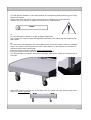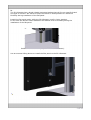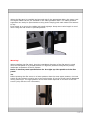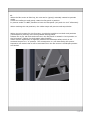
1
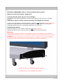
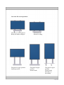
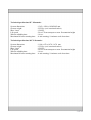
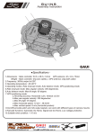
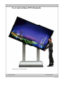
User instructions FP Liftomatic
Suitable for the 85” and 103” LIftomatic
Copyright Audipack
(version 01-03-2010)
Need to knows:
-The feet will only retract when the front (swivel) wheels are in line (drive direction).
-De screen will only lift when the wheels are retracted (only with the 103” Liftomatic).
-De wheels wil only unfold when the screen is in lower position (only with the 103”
Liftomatic)..
-The screen will not lower when it is in pivoted position (portrait position) (only with the
103” Liftomatic)..
-When the wheels are retracting, a warning sound will be heard.
-The weight of the flat screen in lower position is schock absorbed during transport on it’s
own wheels or inside the flightcase.
-The maximum lift cappacity of the lift system is may never be exceeded. Please refer to
the prodyct details on the back of the system for max. load.
-When activating the lift system up and directly down, allow 10 minutes engine cooling
down time.
-Beware of feet and cables on the floor when lowering the system on the floor.
-Beware of the floor switch when transporting the FP liftomatic with a fork lift.
-The portrait limit switch must be set before lowering the screen in Portrair mode (only
with the 103” Liftomatic).
The flat panel Liftomatic is the ideal product for transporting and presenting your large
flat panel monitor.
Please read first and follow up the instructions for handling your FP Liftomatic.
Always use your system or install the flat panel on a flat surface!
1.
The FP Liftomatic is fitted in a rigid Audipack Flightcase.
The remove the system open the flightcase and loosen the safety bar by releasing the
black knob.
2.
To remove the FP Liftomatic the retractable wheels of the lift system must be unfolded.
Plug in the power cord and push the lower down button on the column to activate the
retracted wheel and unfold them.
Push the button until the systems stops automatically.
During the decend of the wheel a warning signal is given.
The FP Liftomatic will raise it selve from the flight case and is ready to be driven out of
the case.
Warning:
When the system is driven out of the flight case, the wheel will only retract again when
they are in drive direction!
3.
The FP Liftomatic has a brand related mounting bracket that will fit your specific brand
and type of monitor. We advise to keep the wheels in lifted position for maximum
flexibility during installation of the flat panel.
Install the flat panel gently while the FP Liftomatic is still in lower position.
In this case the build-in shock absorbers will absorb severe trembling during the
installation of the flat panel.
Build-in shock absorbers (only with the 103” Liftomatic).
Use an external lifting device to install the Flat panel to the FP Liftomatic.
When the flat panel is installed and secured with 2 the appropriate bolts, the power cord
and signal cables can be pre-installed in the cable guidance chain. The cable guidance
segments can easily be opend without using tools. Simply guide each cable from bottom
to top.
Even better is to secure the cables with small tighraps. Keep extra canle length in mind
when using the flat screen in portrait position.
Warning!
When installing the flat panel, keep the ventilation direction of the flat panel in mind
when the flat panel is in pivoted position. It might be possible to adjust the primary
landscape orientation of the lift system.
Refer to the flat panel specifications for the right up richt position of the flat
panel.
3a.
Before pivoting the flat screen in a lower position than the most upper position, the limit
switch on the coloumn must be set on the right height. If not the screen can be damaged
during lowering!!! The right position of the limit switch depends on the size of the flat
screen (only with the 103” Liftomatic).
5.
In transport mode the total weight of the flat screen is mechanically separated from the
drive unit. This big advantage prevents receiving heavy shocks on the drive unit during
transport (only with the 103” Liftomatic).
When activating the system, allow the motor
drive of the wheels to reach both end positions
before activating the lift mechanisme.
Allow the lift mechanisme to lower completely
until the drive units stops by it selve before
activating the wheels motor drive.
The 85” Liftomatic is rubber suspended,
Please keep in mind when transporting over
rough terrain. Too rough terrain be damage the
wheel system or internal components.
6.
When the flat screen is lifted up, the unit can be (gently) manually rotated to portrait
mode.
Unlock the safety pin and gently rotate the flat panel in position.
In portrait mode it is NOT possible to lower the flat panel (only with the 103” Liftomatic).
When reaching the end positions, the rubber stops will prevent end stop shcoks.
When uing the system for the first time, it might be possible to set both end positions
(landscape and portrait) with the adjustable locking plates.
Release the 4 pcs. M6 bolts and make sure the flat panel is rotated in level position on
the lift system. Tighten the bolts again when finished.
AFther severe adjustment it might be possible the landscape safety switch is not
activated anymore in “0” position. The consequence is a not descending lift system.
Reposition the switch that it will be activated when the flat screen is landscpae position
and locked.
7.
IN CASE OF EMERGENCY ONLY, contact Audipack before trying!
Manual override when power supply fails
Lowering the flat panel (do not use for lifting!)
The FP Liftomatic has the possibility of manual decending the flat screen to transport
position.
Important to know is that a manual operation can damage the system.
Lowering the flat panel to transport position; rotate the left hand lever counter clockwise.
Check for enough clearance in the shock suspension. Do not continue too long with
lowering because there is no mechanical end stop, only electrical.
Unfolding the wheels
Lifting the system on it’s wheels; rotate the right lever clockwise.
Whenn the wheel are free from the floor stop using the manual activation.
Warning!
Retracting the wheels manual is not advisable, manouvre the system to the nearest
power socket for electric use. In a emergency situation rotate the right side lever counter
clockwise.
Be aware to stop unfodling the wheels when they are vertikal. Continuing unfodling the
wheels more then there maximum can damage the internal end switches!
The LEFT lever is for manual flat panel lowering
The RIGHT lever is for unfolding the wheels
Overview flat screen positions.
Driven out of the flightcase
Ready for indoor transport
Flat panel in upper position
Landscape mode
Retracted feet
Ready for lifting
Flat panel in upper
position
Portrait mode
Flat panel in upper
position
Portrait mode
Movable, no
decending!
Technical specifications 85” Liftomatic:
System dimensions
System weight
Max. Load
Lift speed
Wheels unfolding time
Maximum lift motor running time
: 1365 x 1820 x 1820/2005 mm
: 225 Kg. (excl. monitor bracket)
: 150 Kg.
: 50 sec. From transport to max. Presentation height
: 10 sec.
: 4 min running, 10 minutes cool down time.
Technical specifications 103” Liftomatic:
System dimensions
System weight
Max. Load
Lift speed
Wheels unfolding time
Maximum lift motor running time
: 1190 x 670 x 1470 / 1670 mm
: 135 Kg. (excl. monitor bracket)
: 150 Kg.
: 20 sec. From transport to max. Presentation height
: 10 sec.
: 4 min running, 10 minutes cool down time.