1
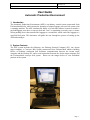
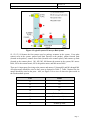
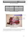
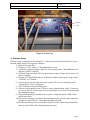
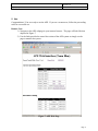
Specification & Design of Real-time Systems
FA_07_SE_545: ERAU TEAM BLUE
User Manual
Automatic Production Environment
Christopher Griffis
Steve Harvey
Leonardo Matos
Jason McGuire
Sean Pfeifer
Caylyne Shelton
User Manual: Automatic Production Environment
FA_07_SE_545: ERAU TEAM BLUE
Version: 1.0
Date: 12/11/07
Document Information
Category
Document ID
Information
User Manual: Automatic Production Environment
Document Owner
FA_07_SE_545: ERAU TEAM BLUE
Revision History
Date
Version
Description
Author
11/29/07
0.1
Initial draft
Caylyne Shelton
12/06/07
0.2
Photo Additions
Caylyne Shelton
12/10/07
1.0
User Guide version 1 release
TEAM BLUE
ii
User Manual: Automatic Production Environment
FA_07_SE_545: ERAU TEAM BLUE
Version: 1.0
Date: 12/11/07
Disclaimer
This document is to be used in conjunction with the APE system, and has been written to guide
the user through successful use of the APE system. Team BLUE will not be held responsible
for any accidents, property damage, etc. that are the result of the use this document with any
system other than the APE, nor will Team BLUE be held responsible such incidents as the result
of misuse of the APE system.
Preface
This document outlines setup guidelines for the APE system. Two types of users exist: remote
users, and local users. Remote users are defined as those which will access the APE system via
a web interface. Remote users may monitor the system’s activities in automatic control mode,
or they may control the system’s activities from this web interface. A remote user may be
accessing the APE system from a computer as close to the APE system as right next to it, or as
far away from the APE system as the internet will allow. Local users are defined as the users
that are on site of the APE system and can physically interact with the system without the need
for a web interface.
iii
User Manual: Automatic Production Environment
FA_07_SE_545: ERAU TEAM BLUE
Version: 1.0
Date: 12/11/07
Table of Contents
TITLE PAGE .................................................................................................................................................................ii
SIGNATURE PAGE......................................................................................................................................................ii
CHANGE HISTORY.....................................................................................................................................................ii
PREFACE ......................................................................................................................................................................ii
1.
INTRODUCTION ................................................................................................................................................1
2.
SYSTEM CONTENTS .........................................................................................................................................1
3.
FISCHERTECHNIK CONVEYOR BELT SYSTEM SETUP .............................................................................2
4.
SOFTWARE SETUP............................................................................................................................................5
5.
USE .......................................................................................................................................................................6
6.
DEFINITIONS, ACRONYMS, AND ABBREVIATIONS..................................................................................7
7.
FURTHER READING .........................................................................................................................................8
iv
User Manual: Automatic Production Environment
FA_07_SE_545: ERAU TEAM BLUE
Version: 1.0
Date: 12/11/07
User Guide
Automatic Production Environment
1. Introduction
The Automatic Production Environment (APE) is an industry control system constructed from
Fischertechnik blocks, which imitate the operation of airport luggage conveyor belt system with
a scanning machine. The APE simulates the ability of a real-time software system to transfer a
payload/luggage item down a conveyer belt and “scan” it (simulating a security scan). A motor
driven pushing device then transfers the luggage to a second belt, which carries the luggage to a
specified final point. This document will guide the user through the process of setting up the
APE and running it.
2. System Contents
The APE system includes the following: one Desktop Personal Computer (PC), one Arcom
target computer, a Conveyor Belt System constructed from Fischertechnik robotics building
blocks, an Ethernet connection that facilitates communication between the Arcom target
computer and the Desktop PC, and a serial connection between the Arcom target computer and
the Fischertechnik conveyor belt system. Please see the images below to view individual
portions of the system.
Page 1
User Manual: Automatic Production Environment
FA_07_SE_545: ERAU TEAM BLUE
Version: 1.0
Date: 12/11/07
Figure 1: Desktop PC
Figure 2: Arcom Target Computer
Figure 3: Fischertechnik Conveyor Belt System
3. Fischertechnik Conveyor Belt System Setup
The Fischertechnik conveyor belt system consists of eight wired connections for the sensors, four
wired connections for the motors, 9 volt DC power input, and a serial connection (connected via
serial cable to the Arcom target computer). See the proceeding logical component diagram to
view the location of the sensors and motors in the system.
Page 2
User Manual: Automatic Production Environment
FA_07_SE_545: ERAU TEAM BLUE
Version: 1.0
Date: 12/11/07
Figure 4: Logical Layout of Conveyor Belt System
S1, S2, S3, S4 denote the four sensors used as package scanners in the system. Four other
sensors exist in the system: pusher back limit (located at the pusher), pusher forward limit
(located at the pusher), scanner down limit (located at the scanner place), and scanner up limit
(located at the scanner place). M1, M2, M3, M4 denote the motors in the system; M1 moves
Belt1, M2 is the scanner motor, M3 is the pusher motor, and M4 moves Belt2.
There are 16 input ports for wiring to the sensors and motors- I1 through I8, and M1 through M8.
All eight sensors should be wired to the I ports as depicted in Table 1. Table 2 depicts how the
motors should be wired to the ports. Also, see Figure 5 for a view of where the ports reside in
the Fischertechnik system.
Port
Sensor
I1
S4
I2
S3
I3
S2
I4
S1
I5
Pusher back limit
I6
Pusher forward limit
I7
Scanner down limit
I8
Scanner up limit
Page 3
User Manual: Automatic Production Environment
FA_07_SE_545: ERAU TEAM BLUE
Version: 1.0
Date: 12/11/07
Table 1: Sensors to Ports Mapping
Port
Motor
M1
M1
M2
M2
M3
M3
M4
M4
Table 2: Sensors to Motors Mapping
DC Power Input
Serial Port
I and M Ports
Figure 5: Fischertechnik View
The serial port should be connected to the Com1 port on the Arcom target computer. An
Ethernet cable should be plugged into the Arcom and it should put the Arcom on the same
network as the desktop PC. See figure 6 for a view of the back of the Arcom box.
Page 4
User Manual: Automatic Production Environment
FA_07_SE_545: ERAU TEAM BLUE
Version: 1.0
Date: 12/11/07
Ethernet
Com1
Figure 6: Arcom View
4. Software Setup
Software setup is completed on the desktop PC. Follow the instructions listed below to Load a
bootable image onto the Arcom target computer.
1) Open the Tornado IDE.
2) Navigate to “File->Open->C:/BootableWebserver.wsp”
3) Inside the workspace window right click on the project name (“BootableWebserver”)
and select ‘Build ‘VxWorks’.
4) The Build Output window will come up and once it shows “Done with no errors” the
build is complete.
5) Navigate to C:/BootableWebserver in Windows Explorer and copy the image called
“VxWorks” to C:/BootId.
6) Turn on the Arcom and at the same time start the FTP server by navigating in the
Tornado IDE to “Start->FTP Server”.
7) The FTP Window called WFTPD opens.
8) After the Arcom initializes, the FTP server starts communication with it. If there are
no errors in the FTP window and on the Arcom display, the Arcom will automatically
start loading the image.
9) The Fischertechnik goes through a test sequence- during this time the USB, COM,
and IR lights flash.
10) Once the test sequence is complete, push the button to the left of the ports (and above
the lights) to select PROG1. Once again the lights will flash.
11) Push the Port button twice to select the COM port (COM will be lit up) and hold for
three seconds (COM will be flashing during this time).
Page 5
User Manual: Automatic Production Environment
FA_07_SE_545: ERAU TEAM BLUE
Version: 1.0
Date: 12/11/07
5. Use
Congratualtions! You are ready to use the APE. If you are a remote user, follow the proceeding
rules for successful use.
Remote User:
1) Navigate to the APE webpage in your internet browser. The page will look like that
depicted in Figure 7.
2) Use the links provided to control the actions of the APE system or simply use the
page to monitor the system.
Figure 7: APE Web Page
Page 6
User Manual: Automatic Production Environment
FA_07_SE_545: ERAU TEAM BLUE
Version: 1.0
Date: 12/11/07
6. Definitions, Acronyms, And Abbreviations
Active – a motor is active if the motor is powered and turning
APE – Automatic Production Environment
Auto Control Mode – This is the default software mode in which control of the system occurs automatically and
without user intervention.
BELT1 – the conveyer belt driven by Motor1.
BELT2 – the conveyer belt driven by Motor2.
Detect – the sensor "detects" an object if the light path is occluded such that the sensor does not detect light,
therefore detecting an occluding object instead.
END PLACE – the last logically detectable position the package can be in.
Extended - the pusher moves to "extended" when it pushes the object away from scan place towards the
TRANSITION PLACE.
Home – a scanner in the home position is the most retracted position as detectable by the position switch such that
the package can enter the scanning area. The pusher in the home position is in the furthest most position from the
transition area as detectable by the position switch and is such that the package can enter the scanning area.
Inactive – when the motor is not moving because it is not being powered, it is considered inactive
M1 – Motor1
M2 – Motor2
No detect - the sensor does not detect an object if the light path is not occluded such that the sensor does detect
light, therefore not detecting an occluding object.
Package – the object used to model the payload that is acted upon in the APE system.
Pusher – the apparatus used to move a package from the SCANNER PLACE to the TRANSITION PLACE
S1 – line sensor 1
S2 – line sensor 2
S3 – line sensor 3
S4 – line sensor 4
SCANNER PLACE – see Error! Reference source not found.; the next sequentially and logically detectable
position a package can have in the system after being moved by BELT1 away from START PLACE. A package can
be scanned only if it is detected in the SCANNER PLACE.
Scanner – the apparatus used to model the systems ability to scan a package.
Page 7
User Manual: Automatic Production Environment
FA_07_SE_545: ERAU TEAM BLUE
Version: 1.0
Date: 12/11/07
Scanning - the scanner is in its lowered position such that it triggers the position switch to detect such a position.
START PLACE – the first sequentially and logically detectable position a package can have in or when being
introduced into the system
TC – Target Computer
TRANSITION PLACE – the next sequentially and logically detectable position the package can be in after it has
been scanned and pushed onto BELT2.
User Control Mode – This is the alternate software mode in which automatic control of the system is suspended to
allow the user direct control over the system motors.
7. Further Reading
[1] Kornecki, Dr. A.J., “Embry-Riddle Real Time Class Resource: Description of the SE545 Project.” SE545
Project System Description 8/10/2007, Version 01 - draft 1. Fall 2007.
[2] www.fischertechnik.com/ Fischertechnik Website
[3] www.arcom.com/ Arcom Website
.
Page 8