1
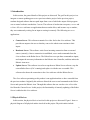
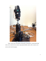
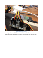
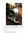
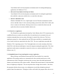
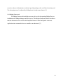
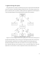
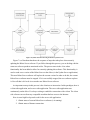
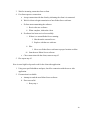
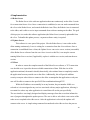
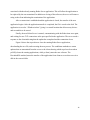
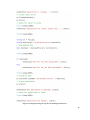
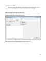
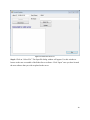
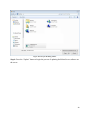
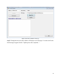
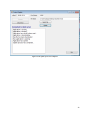
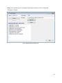
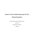
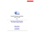
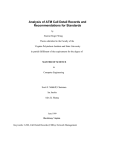
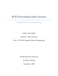
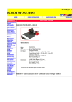
Remote Software Updater for eBox 2300 and Windows CE6 Adrian Saldivar and Kyle Rosier CEN 4935 Senior Software Project Dr. Janusz Zalewski Florida Gulf Coast University April 4, 2012 1. Introduction In this section, the general details of this project are discussed. The goal for this project is to integrate a remote updating process to a previous robotics project. In the previous project, students designed software that accepted input from a user of which the output of this program was to control a robotic arm that has 5 servos. The software is broken into two parts, a server and a client. All server software are applications that run on the eBox, and in some way or another, they run continuously waiting for an input to coming in remotely. The following are server applications: Camera Server: This software transmits live video feed to the client software. This provides an output to the user so that they can see the robotic arm reactions to their inputs. Rowboats Server: This software waits for an incoming connection from an external source (remotely). Once a connection is established, a user sends commands from the client software to the Robot Server. The Robot Server accepts these commands as inputs, and outputs the necessary information to the Robotic Arm Controller, and thus makes the Robotic Arm move. Update Server: This software is used to accept the new Robot Server software, stop the current Robot Server (if it’s running) and replace it with the new executable. This software also shares the connection to the client software with the Robots Server. The client software pertaining to this product is one application that we have extended from the previous students. Originally this software allowed the user to send commands to the Robot Server and operate the Robotic Arm. Through this software the user can also view a live video feed from the Camera Server. In this project, the functionality of remotely updating of the Robot Server is added to this client software. 1.1 Physical Devices In this section, the physical devices involved in this project are discussed. Figure 1 shows a physical diagram of all physical entities involved in this project. Physical entities include: 2 The user, a human entity. A computer that runs the client software. A connection by this computer to the Internet. A thin client (the eBox server). A connection to the Internet from the eBox server. A web camera with video streaming capability. A SSC-32 Controller which sends signals to the Robotic Arm. An AL5A Robotic Arm. Figure 1 Robot Arm Project - Physical Device Interconnectivity Diagram [1] All of these devices, connected in such a way shown in Figure 1, enable the functionality present in this project. 1.2 Development Environment Information A variety of technologies come together in this project. In this section, the specific development technologies used throughout this project are discussed. A basic understanding of threads, processes, and the Transmission Control Protocol is required for all of these software programs. Client The client application was created using the C# programming language, the XNA Framework, and the .Net Framework. These technologies make it possible for the user to remotely connect to the Robot Server, send commands to control the Robotic Arm, view the live video stream from the Camera Server, and upload/update the Robot Server software remotely. 3 Robot Server The Robot Server application was developed using the C# programming language and the .NET Framework. This software is deployed on the eBox 2300 thin client that runs a Windows CE6 environment. These technologies enable an application to run continuously waiting for a connection over a network (in this case, the Internet). Once a connection is established, the client software can send data over the network to the Robot Server. The Robot Server is also responsible for relaying commands from the user to the Robotic Arm, enabling the user to control it. Camera Server The Camera Server application was developed using the C# programming language and the .NET Framework. This software is deployed on the eBox 2300 thin client that runs a Windows CE6 environment. This application enables live video streaming over a network (the Internet) to client software once a connection has been established. Update Server The Camera Server application was developed using the C# programming language and the .NET Framework. This software is deployed on the eBox 2300 thin client that runs a Windows CE6 environment. This software is a new application for this project, which allows a user using the client software to remotely upload and update the Robot Server software. 4 2. Hardware and Software 2.1 Hardware Figure 2 The eBox 2300 Thin Client [2] Figure 2 shows the eBox 2300. This device is considered a thin client, which is sometimes called a lean client. This is a low-cost, centrally-managed computer devoid of CDROM players, diskette drives, and expansion slots.” The eBox 2300 is the always-on device used in this project as a server and is accessible to clients/users in a LAN or WAN. 5 Figure 3 The Lynxmotion AL5A Robotic Arm [4] Figure 3 shows the AL5A Robotic Arm made by Lynxmotion is a small robot kit that utilizes servos that allow base rotation, single plane shoulder rotation, elbow rotation, wrist motion, and a functional gripper. 6 Figure 4 The SSC-32 Servo Controller Figure 4 shows the SSC-32 servo controller. This controller allows the robotic arm to iterate commands fast and accurately. The AL5A is connected to the eBox via an USB cable. 7 Figure 5 The Logitech QuickCam Pro 5000 The QuickCam Pro 5000 (Figure 5) features a 640x480 VGA sensor. It uses RightLight 2 Technology, an imaging system from Logitech that delivers sharp video even in dim lighting. The Logitech camera is connected to the eBox via an USB cable. 2.2 Software The following software items are required for this project: Microsoft® Visual Studio® 2005 Professional Edition 8 Visual Studio 2005 is the development environment used for creating and deploying applications for Windows CE 6.0. Microsoft® Visual Studio® 2010 Express Edition Visual Studio 2010 is the development environment used for creating the applications that establish a connection with the ebox to control the robot arms. Windows Embedded CE 6.0 Windows Embedded CE 6.0 is a light weight version of Windows intended for mobile devices and thin clients. It is the current operating system for the eBox 2300. It allows the ebox to connect to the Internet, allowing remote users to control the robotic arm and update the software associated with the robotic arm. 2.2.1 Client/Server Application The Client/Server applications developed by Carlos Daboin, allow TCP connections to be established between a remote user and the eBox. Its main function is to transmit video and rotations commands between two points, allowing for control of the robot arm. The Server application streams live video captured from an USB camera and delivers commands to the servos, both of which are connected to the eBox 2300. The server application runs under the Windows CE 6.0 operating system. The Client application receives the streaming video from eBox2300 via the Internet and displays it onto the computer running this application. The client application sends rotation commands to rotate the various servo motors attached to the AL5A Robotic Arm. [5] 2.2.2 Simplified Remote Control and Spatial Awareness Application Robert LaForge used Windows Forms and XNA Game Studio 4.0 to create this application. The program sends servo commands to the ebox and robot and receives video transmission in return. Through a circular map, the user may choose the radial position and distance out from the base of the robot in inches. When the left mouse button is clicked and held down, a height map is displayed. The user may then select a height, also in inches. On release, the program calculates the necessary servo adjustments to reach the destination point and prepares them for transmission. Through use of the scroll wheel, the program allows the user to 9 move the robot to the destination at a desired speed depending on the scroll wheel rotation speed. The robot gripper may be adjusted by holding down the right mouse button. [1] 2.2.3 Phidget Framework The Phidget Framework installs the necessary drivers for the operating Phidget Devices in addition to the Phidget Manager and Web service. The Phidget Framework allows the eBox to translate information received from the Simplified Remote Control and Spatial Awareness Application into commands the servo controller can understand. [3] 10 3. Application Design Description The software that was created to extend the previous project is discussed in detail within this section. This software is described in diagrams within this section. The software consists of two parts: an extension to the client software, and the Update Server application. The first diagram is a static description diagram of the interoperation between these software products. Figure 6 Structure Diagram Showing the Update Process Figure 6 is a structure diagram that shows the update process. The extension of this project is to include this functionality to the previous project. This diagram describes the overall structure of this functionality. Again, there are two software products involved in this product and described in the diagram. The first is the client software. The client connects to the Update Server, then this connection is used to send/receive a new version of the Robot Server. Once the Update Server receives this new version, it replaces the current version with the new one. 11 Figure 7 Dynamic Flowchart Showing the Remote Update Process Figure 7 is a flowchart that shows the sequence of steps that take place when remotely updating the Robot Server software. If you follow through this process, you are dealing with the same two software products mentioned earlier. The process starts in the client where functionality has been added to allow for remotely updating this software. This functionality is used to send a new version of the Robot Server to the eBox (via the Update Server application). This new Robot Server software will replace the current version. In order to do this, the current Robot Server software must be stopped. If it is successfully stopped, the new software replaces it. Now all that is left to do is to start the new Robot Server software. An important concept in this process is the client/server interaction. In this paradigm, there is a client side application, and a server side application. The server side application runs continuously on the eBox. It’s always waiting to establish a connection with a client. The client side software can run from any compatible machine that has access to the Internet. Here is some high-level pseudo code for the server side application: 1. Obtain status of current Robot Server software (is it running). 2. Obtain status of Internet connection. 12 3. Wait for incoming connection from a client. 4. If a client requests a connection: a. Accept connection with the client by informing the client it is connected. b. Wait for client to begin transmission of new Robot Server software. c. If client starts transmitting the software: i. Receive the new software. ii. When complete, inform the client. d. If software has been received successfully: i. If there is a current Robot Server running: 1. Shut down the current Server. 2. Replace with the new software. ii. Else: 1. Move new Robot Server software to proper location on eBox. iii. Start the new Robot Server software. e. Close connection with the client, return to step #3. 5. Else repeat step #3. Here is some high-level pseudo code for the client side application: 1. Using user specified address and port, check for connection with the server side application. 2. If connection is available: a. Attempt to send the new Robot Server software. b. If not successful: i. Retry step a. 13 4. Implementation 4.1 Robot Server The Robot Server is the software application that runs continuously on the eBox. It waits for a connection from a client. Once a connection is established, a user can send commands from the client to the Robot Server, and control the Robotic Arm. Thus, the Robotic Arm is connected to the eBox, and is able to receive input commands from software running on the eBox. The goal of this project is to make this software application (the Robot Server) remotely updateable from the client. To handle this update process, a separate software entity is required. 4.2 Update Server This software is a new part of this project. Like the Robot Server, it too resides on the eBox running continuously. It too is waiting for a connection from the client software. Once a connection is established from a client, the Update Server can receive a new version (executable) of the Robot Server software from the user. Once it receives this file, it can stop the current running Robot Server version (if applicable), replace it with the new version, and start the new version. 4.3 Client In order to ensure the complete transfer of the Robot Server software, a TCP connection was decided on as it provides the most reliable transmission of data. With the size of the application minimal, the transfer should, theoretically, take minimal time to completely transfer the application from any outside user to the eBox. Additionally, this will provide addition security to anyone who wishes to connect to the eBox to manipulate the application as only one user will be able to connect to the specific IP/Port combination through TCP. While the IP address can essentially be at any location, the port number 16888 was selected as it is not assigned to any services associated with any major applications, allowing it to remain free unless any other application is created that will use the port specifically. The user interface was simply designed and displays messages from the server that informs the user of progress throughout the update process. The user is able to select their own version of the robot server to upload to the eBox server. After the application is selected, the updater will connect to the server. A simple string command is transferred to the eBox to close the process 14 associated with the already running Robot Server application. This will allow the application to be replaced by the one transmitted. In addition to closing of the software, the server will return a string to the client indicating the termination of the application. After a connection is established and the application is closed, the transfer of the new application begins. After the application transfer is completed, the file is saved to the disk. The application is saved to “\Windows\robot\” giving it a central location that all necessary drivers and executables to be stored. Finally, the new Robot Server is started, communicating with the Robot Arm once again, and waiting for new TCP connections at the port specified in the application. The server sends a response to the client indicating that the update has completed and the connection closes. Figure 8 shows the steps taken to close the running Robot Server application, downloading the new file, and executing the new process. The sendStatus methods are status updates that are transmitted from the server to the client showing which steps have been taken. pr.Kill() closes the running applications, while pr.Start() starts the new software. The DownloadFile method, starts the transfer of the application from client to server then saves it to disk in the correct folder. 15 Figure 8 Code Snippets showing the steps taken for updating the Robot Server 16 5. References [1] LaForge, S. “AL5A Robotic Arm Project: Web‐Based Control with Spatial Awareness and Intuitive Manipulation” p2 April, 2011 <http://itech.fgcu.edu/faculty/zalewski/CNT4104/Projects/Robotic_Arm_Final4.pdf> [2] “EBox-2300.” EBox 2300 Compact PC. Embeddedpc.net. 19 Jan. 2011 <http://www.embeddedpc.net/eBox2300/tabid/110/Default.aspx> [3] "Products for USB Sensing and Control." Phidgets Inc. - Unique and Easy to Use USB Interfaces. Phidgets.com. 1 Feb. 2009 <http://www.phidgets.com/> [4] "Products." Robotic Arms. Lynxmotion, Inc. Web. 16 Jan. 2011. http://www.lynxmotion.com/Category.aspx?CategoryID=27 [5] Daboin. C. “Software System for Remote Measurement and Control Implemented on the eBox 2300 Thin Client.” p. 9. June 2009. <http://itech.fgcu.edu/faculty/zalewski/projects/>. 17 Appendix A. User Manual This section describes the deployment of the Remote Software Updater (RSU). This is a guide on how to use the RSU software to deploy updated Robot Server to the eBox. Step 1: Launch the Remote Software Updater (RSU). Step 2: Provide IP address and Port Number for where to reach the server. Defaults are already entered into the text fields. Change these if necessary. Figure A1 The RSU software displayed after launching Step 3: Press the “Connect” button to attempt to connect to the server. 18 Figure A2 Connected to the server Step 4: Click on “Select File”. The Open file dialog window will appear. Use this window to browse to the new executable of the Robot Server software. Click “Open” once you have located the new software that you wish to upload to the server. 19 Figure A39 The open file dialog window Step 4: Press the “Update” button to begin the process of updating the Robot Server software on the server. 20 Figure A4 The new executable is ready to go Step 5: During this time, the status window will display several messages. You must wait for the final message to appear which is “Update process has completed…”. 21 Figure A5 The update process has completed 22 Step 6: Now that the process is complete, disconnect from the server by clicking the “Disconnect” button. Figure A6 Disconnected from the server 23