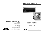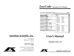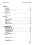
1
ValveLink™ 8&16
User’sManual
AutoMateScientific,Inc.
336BadenStreet
SanFrancisco,CA94131
U.S.A.
Version2.2
(800)998-MATE
-6283
international(415)239-6080
fax(415)239-6801
[email protected]
wwwhttp://www.autom8.com
AutoMateScientific,Inc.
ValveLink8 - Part #01-18
For indoor use only from 5° to 40° C.
Do not get wet or subject to visible condensation.
Clean with a mild soap solution with a damp cloth only.
This equipment must be earth grounded. Use any of the
screws on the bottom of the case. See page 12.
!
Do not unplug valves while on!
Do not attempt to repeatedly cycle valves on and off in under
10 milliseconds.
If this equipment is used in a manner not specified by the
manufacturer, the protection provided by the equipment may
be impaired.
Supply voltage:
ValveLink8 controller = 12 V AC up to 2.4 Amps @ 50-60 Hz
External power supplies:
USA & Japan = 110 V AC up to 0.26 Amps @ 60 Hz
European = 220 V AC up to 0.17 Amps @ 50 Hz
Internal battery type:
3V Lithium coin battery
type BR2325 coin or CR2032
23mm x 165mAh
Please replace fuse with standard 2.5 Amp (M) medium-time
/ blow fuse.
ValveLink™8&16
User’sManual
Version2.2
The ValveLink is intended for research use only.
Table of Contents
Introduction .......................................................................................2
Hardware overview, Applications, Lure-lock valves and syringes,
Pressure upgrade, PerfusionPencil™ manifold
System Set-Up Diagrams .................................................................5
Perfusion systems, Micro-manifold installation, Pressure Kit, Multibarrel Perfusion Pencil, Chromatography, Gel/Blot washing
Operation ........................................................................................ 11
Manual control, 3-way valves, Back panel, Case and valve grounding
Modes ................................................................................................13
Serial Communications .................................................................16
Techniques.........................................................................................18
Dead volume, Small-bore Teflon tubing, Backflow, Syringe reservoirs,
AutoPrime™ System, Faulty valves, Leaks, Replacing valve fittings,
Hardware troubleshooting
Safety Instructions............................................................................25
Warranty............................................................................................27
Josef Kewekordes II, Heath Lukatch, Dave Ilstrup, Gabriel Stern
©1996, 2000 AutoMate Scientific, Inc.
All rights reserved.
Introduction
ValveLink Laboratory Applications
The ValveLink is designed for solution-switching use in research applications ONLY. AutoMate Scientific, Inc. cannot be responsible for
injury or death resulting from medical or pharmacological use.
Perfusion
A ValveLink can be programmed to precisely switch solutions
perfusing over biological samples for physiological research. The
ValveLink’s circuitry is designed to open valves with low noise for
electrophysiological amplification. Several features, ‘Modes’ have
been built into the ValveLink for advanced perfusion use.
FOR RESEARCH USE ONLY
Hardware Overview
The ValveLink 8 and 16 are simple digital/manual valve controllers
designed for use with research automation software. Valves can
be controlled by digital TTL* signals from any I/O card or device.
Eight pushbuttons allow manual user control with eight bi-colored
LED indicators (16 LED’s for ValveLink16’s plus a ‘bank’ selector
switch described later). A serial (RS-232) port is provided for further valve control by serial devices. All three input sources (digital,
serial, and push buttons) are simultaneously active, and the LED’s
constantly display the current valve status.
™
The ValveLink is designed to drive 12 volt DC solenoid valves
plugged into RCA jacks on the back of the box. Why not connect
valves directly to your computer? Several reasons:
1) Most computer interfaces provide +5V signals – not strong
enough to drive most valves (6 to 12V DC and up).
2) Computer interface signals are often too noisy for electrophysiology amplification. The ValveLink is designed with
special low noise circuitry to minimize interference with
high-gain amplification.
3) Finally, many solenoid valves are designed to be opened
with a short, full-voltage pulse, then “held-in” with a lower
voltage to keep the valves from heating. The ValveLink automatically provides dual-voltage hold-in.
* TTL stands for Transistor-Transistor Logic, a +5/0 volt standard for representing
on and off – used by the ValveLink for computer valve control.
2
Washing
Combined with an AutoMate ported washing tray, the ValveLink
can automate washing of electrophoresis gels and blots, and developing of x-ray or photographic film or prints. You have complete
control over which washing steps of your Western, Northern, Southern, Coomassie Blue and Silver staining runs are automated and
which are handled conventionally. Unattended washing can save a
busy lab countless hours of tedious monitoring.
Liquid Chromatography
A ValveLink can be easily programmed to automate solution selection in multi-step ion exchange, gel filtration or affinity chromatography runs with excellent reproducibility. The ValveLink
is especially useful in preparative work when a protocol has been
established and programmed to repetitively isolate your valuable
molecule.
Luer lock Valves and Syringe Reservoirs
AutoMate also offers
valves with luer lock fittings for direct connection
of syringes. This method
eliminates wasted solution in tubing between
the reservoirs and valves.
Small 2-way stopcocks are
included when this option
is ordered.
3
System Set-up Diagrams
Pressure Regulated Perfusion System
AutoMate Scientific now offers a Pressurized Perfusion Upgrade
with either four or eight channels for:
• Faster Switching
• Microliter fine delivery
• Small diameter pipette delivery
Perfusion System
Instructions on this page for Economy perfusion systems, Lure-lock
fittings, Pressurized systems or Pinch
valve systems. (Regular hose barb
Teflon perfusion systems please see
the next page.)
Lure-lock systems should also see
photo on page 3. Find additional
photos and diagrams of the pressure
system on pages 4 and 8.
• Steady flow-rate
• Microinjecting
The package can be added to
any new or existing perfusion rig - from AutoMate,
any third-party manufacturer, or even homemade.
Connect to house air, tank,
or compressor (30 to 100
psi). Precision regulator
delivers zero to 10 psi.
1
2
3
4
Flow rate adjusted by relative height of
reservoirs and included flow regulator.
Always calibrate flow rates - regulator
values are relative (see below).
Leave tubing between reservoirs and
valves long enough to raise and lower
reservoirs.
1) Assemble ringstand.
For Single-cell or Whole-cell Superfusion
Multi-barrel Perfusion Pencil™
8 micro-bore tubes
into 1 outflow
• Single cell and
patch delivery
• Rapid solution
change
• Micro-liter dead
volume
• 250 & 100 micron
removable tips
4
vacuum
trap
*Unused lines should be replaced with
plugs on manifold, or temporarily
clamped-off just above manifold to
avoid back bleeding into empty lines.
Priming one line at a time reduces
bubbles.
Connect your vacuum trap line directly
to the outflow of the manifold for running cleaning solutions and drying your
lines quickly.
Determine dead volume from the
manifold to sample by measuring
time and volume required to flush a
colored liquid with a clear one.
2) Attach valve unit.
3) Attach reservoir bracket(s).
4) Insert reservoirs.
5) Attach provided tubing to upper
valve barb (cut as desired, but see
note above first).
6) Connect tubing between bottom
valve barbs and manifold.
7) Connect flow regulator tubing
to manifold outflow and your
perfusion chamber (downsizing if
necessary).
8) Plug numbered valve cables into
ValveLink ports.
Calibrate flow rates by running one line
into a graduated cylinder for a fixed
period of time.
5
Standard Teflon Perfusion System (without pressure)
Teflon Micro-manifold Use
Your valves should be equipped or retrofitted with 1/16” o.d.
outflow hose barbs. Micro-manifolds are shipped with a short piece of
1/16” o.d. tubing in each hole (inputs and outflow). You can either connect
the valves to manifold inports with a piece of 1/16” i.d. tubing over both
the valve barbs and short pieces of manifold tubing:
Flow rate adjusted by relative height of
reservoirs and included flow regulator.
Always calibrate flow rates - regulator
values are relative (see below).
1
2
3
4
Leave tubing between drippers and
valves long enough to raise and lower
reservoirs.
1) Assemble ringstand.
*Green clamps
close to manifold
vacuum
trap
*Unused lines should be replaced with
plugs on manifold, or temporarily
clamped-off just above manifold to
avoid back bleeding into empty lines.
Priming one line at a time reduces
bubbles.
Connect your vacuum trap line directly
to the outflow of the manifold for running cleaning solutions and drying your
lines quickly.
Determine dead volume from the
manifold to sample by measuring
time and volume required to flush a
colored liquid with a clear one.
6
2) Attach valve unit.
3) Attach reservoir bracket(s).
4) Insert reservoirs.
5) Insert short pieces of 3/16 i.d. tubing
over tops of drippers, then insert
over reservoir nipples.
6) Attach dripper tubing to upper valve
barb (cut as desired, but see note
above first).
7) Insert green clamps on short pieces of
1/16 tubing.
8) Connect tubing between bottom
valve barbs and manifold.
9) Connect flow regulator tubing
to manifold outflow and your
perfusion chamber (downsizing if
necessary).
10) Plug numbered valve cables into
ValveLink ports.
Calibrate flow rates by running one line
into a graduated cylinder for a fixed
period of time.
Valve with 1/16” o.d. barb
v
1/16” i.d. tubing over barb
and over manifold short tubing
v
Manifold with short pieces of 1/16” o.d. tubing in each port
... or, for even less dead volume, use a short piece of 1/16” i.d. tubing
over the valve barb, and piece of smaller 1/16” o.d. tubing inserted inside
the valve tubing and manifold ports (you may need to supply extra small
tubing for this option):
Valve with 1/16” o.d. barb
v
Short piece of 1/16” i.d. tubing over valve barb
v
Small diameter 1/16” o.d. tubing inserted inside valve tube
and inserted inside manifold ports
v
Manifold without connector tubing. 1/16” i.d. holes.
Cutting the tubing at an angle will make insertion easier. Cutting the
tubing square, however, will minimize dead volume when inserted as
far as possible into the manifold – being careful not block at the point of
convergence.
Remember to keep all tubing as short as possible.
7
Perfusion Pressure Kit (sold separately #09-04, -08 & -16)
Press regulator knob down to lock.
Pull up to unlock.
Multi-barrel Perfusion Pencil™ (sold separately)
#04-04-xxx
#04-08-xxx
#04-16-xxx
4-into-1 Pencil with tip
8-into-1 Pencil with tip
16-into-1 Pencil with tip
(xxx = 100, 250, or 360 µm)
Brass input connector hose barb size 1/4” i.d.
Max. input
pressure 100 psi!!
Tighten removable tip for
minimum dead volume.
Replacement Tips:
Part No. Description
04-xxx
specify
100, 250, or 360 µm
Epoxy or silicon glue may be needed to
completely seal connections between valve
tubing and the manifold tip in-ports.
Individual air lines can be
adjusted or turned-off.
One of the eight lines may be connected to vacuum through a valve
programmed to suck the dead-volume clear between solutions.
5 micron bowl filter.
Press bottom button to empty.
Be very careful with these
plastic hose connections.
Syringes may also be placed in a water
bath for temperature control.
2-way stopcocks and lure-lock to 1/16” hose fittings are
included for each channel to connect syringes to hose.
Hoses should continue from syringes to valves
8
Chemical Information
The tubing inside the manifold body is polyimide (nylon). The largest
connection tubing is vinyl. The Removable tips include a medical grade
polypropylene Luer-lock fitting with a fused silica (quartz) needle coated with
polyimide. These materials are resistant to most acids, bases and organic solvents.
To avoid dust contamination, we recommend pre-rinsing the Perfusion Pencil and
Tip with distilled water. Also, it is good practice to discard the first few microliters
of solution before using the device. The Perfusion Pencil and Removable Tips are
shipped non-sterile. They can be chemically sterilized or autoclaved. However,
repeated autoclaving may weaken the adhesive bond between the Lure-lock fitting
and the needle.
Maintenance
You can expect several years of useful lifetime for your tip if you wash it daily. Use
a syringe or vacuum to pull first water, then alcohol three times each through the
tip. If the Multibarrel Perfusion Pencil is filled with pure salt solution, leaving it in
the syringe overnight will not usually cause the tip to block. However, if it is used
for high viscosity fluids, flushing after each use is recommended.
Cutting
The Removable Tips are shipped with 1.5" (3.8 cm) length polyimide needles. They
are intended to be cut to a desired length by rolling a razor blade on them against
a hard surface. However, this may leave a small crack or barb on the tip. To get a
flat cut, score the coating of the needle with a ceramic cleaving stone or a diamond
cutter and pull directly apart, making sure not to pull at an angle. You may notice
a larger outer tube enclosing the lower part of our smaller, 100µm needles. This is
simply for added rigidity, and can be cut if needed.
9
Chromatography
Without a pump, flow rate
is determined by relative
height of reservoirs.
1) Position reservoirs above
column ringstand.
2) Attach valve unit to column stand.
1
2
3
3) Run tubing from upper
valve barbs into res ervoirs.
4
4) Connect short pieces of
tubingbetweenlowervalve
barbs and manifold.
Fraction
collector
or waste
5) Connect manifold outflow
to your pump with 1/16"
i.d. tubing.
6) Pump outflow connects to
column inlet as usual.
7) Plug numbered valve cables
Gel/Blot Washing System
1) Position reservoirs above
washing area.
2) Attach valve unit to ringstand.
2
3
3) Run tubing from upper valve
barbs to reservoir nipples.
4
4) Connect tube from lower
valve barbs to tray inlets.
vacuum trap
5) Connect tray outflow to
fourth upper valve barb.
rocker
10
With a ValveLink8, a researcher can turn valves on and off
using eight TTL pins
from an interfacing board on a personal computer and their own custom programs. (See the description of Mode #1 in the next chapter to accomplish this using
only three or four TTL outputs.) The ValveLink will open and close
valves mirroring the computer signals (low = off, high = on) with
sub-10 millisecond accuracy. ValveLink16’s have one additional
TTL input to ‘multiply’ the eight common inputs by 2 into 16 full
channels of valve control.
ValveLink8
[Back panel diagram view]
Standard female DB-9 connector
Pins 5,4,3,2,1 = TTL inputs 0-4
5
1
9
Pin 6 =
ground
Pins 9,8,7 = TTL inputs 5-7
Flow rate is determined by
relative height of reservoirs.
1
Operation
6) Connect this valve’s outflow
to vacuum trap.
7) Plug numbered valve cables
ValveLink16
Female DB-15 connector
Pins 8,7,6,5,4 = TTL inputs 0-4
Pin 12 = ground
1
8
15
Pins 15-13 =
TTL inputs 5-7
9
Pins 3 = TTL bank
select
Manual Control
Each press of a front-panel pushbutton toggles its valve on
and off. The ‘Reset’ button immediately turns ALL valves off and
resets the ValveLink’s internal circuitry. The ValveLink16 includes
16 valve status LED’s, but has only eight pushbuttons like the
ValveLink8. An up/down switch toggles the ValveLink16’s pushbuttons between control of two ‘banks’ of eight valves.
3-way Valves
The ValveLink also supports 3-way, single-solenoid valves (2
wire). Program the ValveLink as you normally would for 2-way
valves, after determining which of two inlets or outlets are opened
with the on and off states.
11
Modes
Back Panel
12 V AC Power (up to 2.4 Amps @ 50-60 Hz)
Serial (RS-232) Ports:
In (computer) and Out
(next device in chain)
See page 16.
12 V DC valves
Serial Address
(pg. 16)
Digital inputs
(see previous page)
The ValveLink includes several useful features as auxiliary
‘Modes.’ The user alters the current mode settings by holding button #0 down while powering the ValveLink on or while pressing
and releasing the Reset button. LED #0 should begin flashing. Individual modes are toggled on and off by pressing their button while
LED #0 is flashing. The LED associated with each button should
change from red to green, with green representing ON. All of the
modes can be used simultaneously, except numbers 1 and 2 which
cannot both be on. Press button #0 to return to normal ValveLink
operation with any modes activated.
The ValveLink cannot remember which modes are active
when powered off. Therefore, all modes are deactivated when the
ValveLink is turned off or unplugged. However, modes are maintained after pressing the Reset button. Hold button #0 down while
resetting the ValveLink to view and change the current mode settings as described above. NOTE - Reset also closes all valves.
Mode Descriptions
#1
110 or 220 V AC Power
Case & Valve Grounding
This equipment must be earth grounded. Use any screws on
the bottom of the ValveLink case for grounding. Order AutoMate
part no. 01-05 “Low noise, valve and case grounding package” for
an extra grounding wire attached to each individual valve extending back to the controller. Each of this item grounds four (4)
valves. Please order two for eight channel perfusion systems. This
item must be ordered at the same time as the valves. Connect the
ground wire from the valves to a screw on the bottom of the controller case.
12
Binary Demultiplexed Addressing Mode
(Valves 0-7 for two ValveLink8’s)
TTL inputs 0-2 decode into a binary number 0-7
representing which valve to open. When this 3-bit number changes,
the previous valve is closed. When Mode 1 or 2 is used, TTL inputs
0-3 are used for addressing and no longer directly control valves 0-3.
Example: TTL input 0000 0101 opens valve 5 (its decimal equivalent). For ValveLink16’s, additional bit 3 is used as described in the
next paragraph to further select bank 2.
#2
Addressing Mode - Valves 8-15 (2nd ValveLink8)
This is the same binary decoding of bit 0-2 as Mode
#1, but bit 3 is used to select between two ValveLink8’s and control up to 16 valves with a single 4-bit TTL source. Set the first
ValveLink8 to Mode 1, the second to Mode 2, and connect TTL input
bits 0-3 from both ValveLinks to your digital output. Bits 0-2 decode
which valve is opened on the ValveLink selected by the fourth bit
13
(high = ValveLink in Mode 2 & low = ValveLink in Mode 1). As
in Mode 1, TTL inputs 0-3 are used for addressing and no longer
directly control their respective valves. Example: TTL input 0000
1001 opens valve 9 (valve 1 on the second ValveLink8.)
#3
Pre-selected Valve Mode
When Mode 3 is activated, the user is prompted to
press a button 0-7 immediately after leaving mode selection (all
LEDs will flash waiting for a single push button selection). Thereafter, the valve selected is toggled on and off by TTL input bit #7.
This mode allows a researcher to permanently connect a single TTL
output to ValveLink input seven, and select which of eight valves to
activate with that single TTL signal. This mode prevents input #7
from controlling valve #7 as it normally would, unless valve #7 is
chosen as the ‘pre-selected’ Mode 3 valve.
#4
Master Valve
When Mode 4 is selected, the user is prompted to
press a button 0-7 immediately after leaving mode selection (as
Mode 3). This valve then becomes the master valve. Thereafter,
whenever all other valves have been closed through push buttons,
TTL inputs, or the serial port, the master valve will automatically
open. This feature is useful if a control solution is required whenever all other solutions are stopped.
#5
One-at-a-time Mode
When active, Mode 5 automatically closes all other
valves whenever a valve is opened – either by push button, TTL
input, or serial input. This guarantees that no more than one valve
is open at a time. The only exception to this mode is an All Open
command through the serial port (code 192).
#7
4800 Baud
The ValveLink normally expects serial communications at 9600 baud. When Mode 7 is active, the ValveLink listens
for serial codes at a slower 4800 baud rate.
While several modes decode the TTL inputs, the push buttons
and serial input will always toggle valves according to which modes
are active. Remember button #0 leaves mode setting. If Modes 3
and 4 are both active, the user will be prompted for the Mode 3 ‘preselected’ valve first, then the Mode 4 ‘master’ valve.
14
Multiple modes
As mentioned above, most of the six modes above can be active
concurrently, such as Mode 1 - Addressing, Mode 4 - Master Valve,
and Mode 5 - One-at-a-time. Valves are opened or closed accordingly. Only Modes 1 and 2 cannot both be on simultaneously.
Example mode selection LED’s (red = off, green = on):
0
Blink
1
Off
2
On
3
Off
4
On
5
On
6
Off
7
On
0 blinking = mode select - press button #0 to leave
2 on = Addressing Mode valves 8-15 (2nd ValveLink8)
4 on = Master Valve
5 on = One-at-a-time Mode
7 on = 4800 baud serial rate
In this example, when button #0 is pressed to leave mode selection, all LEDs will flash waiting for the master valve (Mode 4) to be
selected.
Instant mode select
In order to ease mode selection, especially when the ValveLink
is frequently turned on and off, individual modes can be selected
when power is turned on. Just as button #0 is held to enter mode
selection described earlier, instead simply hold down the button
corresponding to the mode to be activated during power on or reset.
It is not necessary to press anything to ‘leave’ or finish instant mode
selection. Only one mode can be activated in this manner at a time.
However, button #6 activates the frequently used combination of
Modes 4 & 5 (master valve and one-at-a-time).
As described under Mode Selection, Modes 3, 4 and 7 each
require specific valves to be designated for their function. The user
will be prompted with all LED’s flashing to select a ‘pre-designated’ or ‘master’ valve after using instant selection for any of these
modes.
15
Serial Communications
All of AutoMate’s controllers are capable of communicating
with a host computer connected to a chain of several devices. Serial
communications must be set to either 9600 or 4800 baud (see Mode
8), and must be sent over a standard null modem cable. Usually this
is a normal serial cable with a null modem adapter
Null modem cable diagram
1
1 (ground)
2
3
3
2
AutoMate has implemented a communications protocol compatible with the one offered by Axon Instruments. All commands
begin with ATn, where n is a single digit from 0-9, indicating the
device number being addressed. The address is set with the Serial
Address switch on the rear of the ValveLink. All commands must
be terminated with a carriage return <cr>. Possible commands are:
All modes are separated by commas. The modes that require parameters (4 & 5) have them specified following a forward
slash, but preceding the comma that separates the next entry. For
example, AT3M+2, 4/11, 5/3, 6<cr> activates modes 2, 4, 5 and 6 on
device 3, with valve 11 specified for mode 4 (preselect), and valve 3
specified for Master mode (5).
Again, all valves are referred to starting with 1.
The modes for purposes of serial commands are:
1 - ‘Straight through' TTL mode. The individual TTL Inputs turn
valves on or off. This is incompatible with modes 2, 3, & 4; mode 1
turns them off.
2 - ‘Low-bank' Binary Addressing mode. Inputs 1-3 are decoded as a
binary number if the fourth TTL Input is low. Turns off mode 1.
3 - ‘High-bank' Addressing mode. Inputs 1-3 are decoded as a binary number if the fourth TTL Input is high. Turns off mode 1.
4 - Preselect mode. TTL Input 8 turns the preselected valve on or off.
Requires a valve number parameter. Turns off mode 1.
5 - Master mode. Requires a valve number parameter.
6 - One-at-a-Time mode.
The baud rate (Mode 8) may not be changed via the serial commands for obvious reasons.
See pages 13-15 for a complete description of these modes.
ATnO<cr>
- Open ALL valves.
ATnC<cr>
- Close ALL valves.
ATnV+v<cr> - Open valve 'v'.
ie. AT6V+3<cr> opens valve 3 on device 6.
ATnV-v<cr> - Close valve 'v'.
ie. AT5V-1<cr> closes valve 1 on device 5.
All valve and mode numbers are 1 based instead of 0 based. That is, on a
ValveLink8, they range from 1-8, and ValveLink16 valves range from 1-16.
ATnM+x,x/y,...<cr> - Activate (turn on) modes.
ATnM-x,x/y,...<cr> - Deactivate (turn off) modes.
16
17
Techniques
Dead volume
Dead volume should be minimized in order to switch solutions as rapidly as possible. Dead volume for this purpose refers to
the volume in the single piece of tubing between the manifold and
final destination (perfusion chamber, 96-well plate, etc.) A certain
amount of time must pass for a new liquid to clear the previous one
from this final piece of tubing. Solution switching takes place at the
manifold - assuming each channel’s tubing has been primed from
its valve to this point. Therefore, the manifold should be positioned
as close to the ultimate destination as possible, while the valves can
be some distance away. The micro-manifolds available from AutoMate Scientific are designed to be inserted without tubing directly
into orifices in some perfusion chambers. This absolutely minimizes
dead volume – resulting in switching times of under a second.
AutoMate Perfusion Systems include a blue disposable flow
regulator which will increase dead volume if used improperly. The
regulator can either be eliminated if controlling flow rate is not
necessary, or positioned before the manifold to eliminate dead volume. However, this second method only controls the flow rate of
individual solutions (instead of all solutions when located after the
manifold). Therefore, the researcher can either limit the flow of a
single liquid, or purchase flow regulators for each line.
A final method for reducing dead volume is to use smaller
bore tubing, although this may also reduce flow rate resulting in the
same switching time as for larger tubing.
Small bore, Teflon tubing
AutoMate Scientific’s micro-manifolds use 1/16” o.d. tube
ports which can either be used with this size tubing, or enlarged up
to 1/16” i.d for valve hose barb fittings. Please inquire about AutoMate’s Teflon tubing and nut and ferrule valve fittings for small
bore use. Also see the micro-manifold instructions on page 7.
Cutting Teflon tubing at an angle makes it easier to insert.
18
Backflow
When a manifold is used in a plumbing arrangement, none of
its ports can be left unconnected, or liquid will simply flow backwards out of the opening. Small, green hose clamps are included
with AutoMate Perfusion System drippers which can be easily attached to short pieces of tubing to act as plugs for unused holes.
Likewise, one must be careful not to open any valve whose
reservoir is completely empty or inflow tube is disconnected. Ordinary solution pressure in other lines will force liquid back up the
outflow tubing, through the valve, and either back into the reservoir
or out the disconnected inflow onto the floor. Again, clamp-off any
unused lines at the manifold or be sure all valves are closed while
changing connections.
Syringe reservoirs
AutoMate offers 30ml syringes (photo on page 3) as alternatives to its 100ml polypropylene reservoir cups. Connected directly
into luer lock fittings in the valves, this method eliminates wasted
solution in tubing between the reservoirs and valves. Small 2-way
stopcocks are included when this option is ordered. These are
placed between the syringe and valve fitting in case syringes must
be disconnected before completely empty. Simply loosen the luer
lock from the valve fitting, and remove the syringe and stopcock together. These stopcocks are also useful if there is a chance of a valve
opening after its reservoir is empty (see above paragraph).
AutoPrime™ System
The AutoPrime Perfusion System is designed to deliver oxygenated (or other gas-saturated) solutions without administering ‘stale’
liquid which has remained stationary in the
tubing long enough to lose its oxygenation.
Unless one uses ‘hard-walled’ (i.e. Teflon) tubing, gas will escape through the
tubing leaving the stale solution with a
ruined pH and gas concentration. The 8channel AutoPrime System uses eight valves
per four liquids, with the second set used as
1
2
3
4
waste
19
‘flush’ valves to waste. Shortly before a solution is to be switched
‘on,’ its flush valve opens and re-primes the upper tubing with fresh
solution from the reservoir down to its delivery valve (where a tee
fitting is located connected to the flush valve.) The flush valve is
then closed, and the delivery valve can be opened. The previous
solution in a delivery sequence can continue to flow while re-priming occurs.
Faulty valves
The bane of all liquid delivery apparatus! Despite AutoMate’s
best efforts and pursuit of high quality valve manufacturers, some
valves fail. How often have space shuttle launches been delayed
due to valve problems? We can only pass along our valve supplier’s
one year warranty with their disclaimer “Improper use or mishandling of the units, in the opinion of the manufacturer, voids this
warranty!” (their exclamation mark too.) In order to minimize valve
problems, please observe these guidelines:
1) Clean your valves after each use. Accumulated debris or
precipitate will rapidly cause leaking valves and seals. Use an inline filter if you expect a chance of particles in your solutions. Put
your AutoMate controller’s programmability to good use by writing a washing protocol. At the end of the day, fill each reservoir
with cleaning solution (distilled water or appropriate liquid), and
press Start. A protocol can be easily written to flush each valve in
sequence. Saline solutions allowed to dry in stainless steel valves
will cause them to rust. This is considered improper use. We also
recommend rinsing your valves once before their first use.
Beware of flaking Teflon tape or silicone fitting glue. Large
debris are often the cause of valve failure. Try backflushing a valve
that is suspected to have failed for this reason by connecting a lightly pressurized liquid to the outflow of the valve while it is energized.
Sometimes this ejects the clog. No Draino!
2) Do not operate AutoMate valves with homemade controllers
delivering over 12V DC, or attempt to cycle them rapidly <10ms.
3) Do not exceed the rated operating pressure (> 100psi).
Before returning any valves to us please check:
1) That it was purchased in the last 12 months (AutoMate and
valve manufacturers record each by serial number.)
20
2) That the valve is faulty and not the controller channel – find
a valve that works in a particular output channel and try the bad
valve in that port to see that it still does not function.
3) If it is leaking, see #1 above and the section below.
If it qualifies for all three of the above, AutoMate will accept
the valve for subsequent return to the factory. Repair or replacement is at their discretion, as AutoMate does not have the ability to
open the valves to determine the cause of trouble. We may be able
to loan replacement valves, which may be billed if the valve factory
finds abuse on the user’s part and refuses to honor the warranty.
Stuck pinch Valves
Occasionally pinch valves will stick closed. Usually this is a
sign that they are about to completely fail, but sometimes they can
be rejuvinated by simply prying them open. First energize (turn
on) the valve; then, using a flat screwdriver, gently force the white
plunger open where it normally pinches the tube closed. The valve
may begin functioning normally. Also, pinch valves will not usually work without a piece of pinch tubing installed.
Valve Cables
One problem that is easy to diagnose and fix is a broken cable
connection. Use any ohmmeter to measure the resistance across
the inner pin and outer ‘barrel’ of the RCA plug end of the valve
cable (while unplugged from the controller.) A resistance of zero
ohms indicates a short, or infinite resistance means one of the wires
is broken in the cable assembly. This occurs most often at the joint
between the heavy black cable and the valve lead wires – under the
heat-shrink tubing, inside the outer black sheath, a few inches from
the valve itself. This can often be reached without completely disassembling the valve enclosure. Simply 1) remove the screw inside
the black valve box holding the plastic sheath in its hole, 2) remove
the black tape at the top of
the sheath and peel it back
Valve enclosure (shown without front plate)
a couple of inches, find the
offending cable (trace it back
1
from the bad valve), and 3)
2
Plastic ‘split loom’ cable sheath.
21
3
carefully slice its heat-shrink tubing longitudinally
to remove it. The wires may have come apart or
Heat
broken here, inside the next piece of electrical tape
shrink
on each
isolating the two leads, otherwise within the cable
cable
or valve itself (which can be further determined
with the volt/ohmmeter). If you find the break, resolder the connection, wrap the inner wires in separate pieces of electrical tape,
retest the valve, and reassemble the sheath following the above
instructions in reverse order.
Valve returns & Replacing a Valve
If you need to return a defective valve, you may either return the entire valve assembly for repair / evaluation, or remove
and return the individual valve from its case. This only involves
five screws: remove the two outer plate screws holding all of the
valves into the black metal case, the single screw holding the plastic ‘sheath’ into its underside hole, the electrical tape at the top and
bottom of the sheath, the offending valve’s cable from the plug end
up through the valve casing, and finally, the two screws holding the
valve on to the front plate.
Please package the valve(s) carefully and ship freight prepaid
to AutoMate’s address on the back cover of this manual. No RMA
number is needed as long as you include a note with the following:
1) Your name, company/institution name, phone number, and
an address to return the repair to.
2) Your original invoice number and date if available.
3) A sentence stating the nature of the problem and any steps
you have already taken to fix or identify it. Does the valve energize
/ click? De-energize? Open / close? Leak?
4) Whether the valve was driven by any device other than an
AutoMate controller (and its operating and holding voltages).
5) The application used with the valve, along with the exact
chemical(s) and the duty cycle (pulse) rate if used.
6) A Statement of Chemical Exposure as follows:
a) These valves have not been exposed to chemicals other than H2O
except as described above. b) All applicable Safety and Handling data
sheets for the above described chemicals are enclosed. c) We accept full
22
responsibility for any injury to AutoMate employees or employees of
the valves original manufacturer caused by handling of the residues
of chemicals contained in or on the valves to be returned.
7) An authorized signature, title, and date.
AutoMate will gladly fax you a form with easy blanks to enter
the above information. We will process your return and notify you
of further information as quickly as possible.
Leaks & Replacing valve fittings
The second bane of all liquid delivery apparatus! These hints
may help:
1) Make sure the valve is turned off! (as opposed to leaking)
2) See all of the guidelines in the previous “Faulty Valves”
section - especially #1.
3) Identify whether the valve leaks constantly, under pressure,
inside or outside. Try backflushing if an internal leak.
4) Check and replace obvious loose or worn tubing.
5) Outside leaks usually occur at the fittings and can be
stopped with a bit of silicone glue, epoxy, super glue (Cyanoacrylate) or Teflon tape around the threads of the dry fitting screwed
back into the valve. Be sure not to use too much glue or tape, as
they can easily cause clogs or leaks of their own. Overtightening
can also cause the plastic fittings to leak – hand tighten.
Glue on valve fittings is intended as a gap filler for small openings between the threads and hole, not as an adhesive. Few glues
will adhere to Teflon.
Hardware troubleshooting
Should the ValveLink LED’s fail to light while power is turned
on, check your power connections, source and on/off switch. Disconnect all valves to check for a short. Check the back panel fuse
on ValveLink16’s. Finally, if all else fails, unplug the ValveLink and
check the fuse on the internal circuit board following these instructions: ValveLink8 – remove all of the screws on the bottom and 6
hex D-connector screws from the rear; or ValveLink16 – remove all
of the screws from the top cover. Only replace the fuse with a standard (not slow-blow) of the same size. One extra fuse is included on
the circuit board in clips labeled “Spare.”
23
Safety Instructions
EPROM Installation Instructions
1) Open the ValveLink case as described in the preceeding
paragraph. Remove the last EPROM
slowly with a flat screwdriver or IC
©2003 AutoMate Scientific
ValveLink
1.3 ___
remover noting the ‘dimple’ orientation
(pin 1) on its left side. Insert the new
chip with the same orientation – being
careful not to bend any pins.
2) Make sure that the ValveLink turns on, then turn it back
off before reinstalling the case top. Save the old EPROM until you
are completely satisfied with the new one.
EPROM’s can be erased and recycled, and they cost around
$3.99 each. So if you’re happy with an upgrade, it’s worth the few
pennies stamp cost for U.S. customers to drop them in an envelope
back to AutoMate. International (or busy U.S.) customers will be
excused if they cannot return old [useless] eproms. :-)
The following instructions pertain to the risk of fire, electric shock, or bodily
injury. Please read all of these instructions carefully.
1. Follow all the instructions and warnings marked on this product or included
in this manual.
2. Do not use this product on an unstable cart, stand, or table. This product
may fall, causing serious damage to the product.
3. Slots and openings in the cabinet and the back are provided for ventilation.
To ensure the reliable operation of your product, and to protect it from overheating,
these openings must not be blocked or covered. Do not use this product on a bed,
sofa, rug or other similar surfaces. This product should never be placed near or over
a radiator or heat register. This product should not be placed in a built-in installation
unless proper ventilation is provided.
4. Never push objects of any kind into the product through the cabinet openings, as they may touch dangerous voltage points or short-out parts that could result
in fire or electric shock. Never spill liquids of any kind in the product.
5. This product should only be connected to the AC power source indicated on
your product system’s information label. If you are not sure of the type of AC power
available, consult your dealer or local power company. Only connect this product to
a power outlet that matches the power requirements of this product.
6. Do not allow anything to rest on the power cord. Do not locate this product
where people will walk on the cord.
7. If you have to use an extension cord with this product, make sure that the
total amperage rating of all equipment plugged into it does not exceed the amperage
rating of the extension cord. Also, make sure that the total of all products plugged
into the main AC power outlet does not exceed 15 Amps.
8. Unplug your product from the main electrical power before cleaning. Do
not use liquid cleaner or aerosol cleaners. Use a damp cloth for cleaning.
9. Do not use this product near water.
24
25
10. Unplug this product from the main power outlet and call for service under
any of the following conditions:
A. If the power cord or plug is damaged or frayed.
B. If liquid has been spilled into the product.
C. If the product has been exposed to rain or water.
D. If the product has been dropped or the cabinet has been damaged.
E. If the product exhibits a distinct change in performance, indicating a need
for service.
STOP!!
If you ever have to remove the main system unit cover, observe the following
precautions:
A. The power supply cord must be unplugged before the main system unit
cover is removed. (Separe le cordon d’alimantation et puis enleve le couvercle.)
B. Once removed, the cover must be replaced and screwed in position before
the power supply is plugged back in. (Apres le couvercle en place et remettre le
cordon d’alimentation.)
Battery Warning Statement
CAUTION
There is a danger of explosion if the battery is replaced incorrectly. Replace
only with the same or equipment type recommended by the manufacturer. Discard
used batteries according to the manufacturer’s instructions. See inside of front cover
for battery specifications.
ATTENTION
Il y a danger d’explosion s’il y a remplacement incorrect de la batterie. Remplacer uniquement avec une batterie de meme type ou d’un type recommande par
le constructeur. Mettre au rebutled batteries usagees conformement aux instructions
du fablicant. See inside of front cover for battery specifications.
VORSICHT
Explosionsgefahr bei unsachgemass em Austausch der Batterie. Ersatz nur
durch denselben oder einen vom Hersteller empfohlenen ahnlichen Typ. Entaorgung
gebraushter Batterien nach Angaben des Herstellers. See inside of front cover for
battery specifications.
26
Warranty
AutoMate Scientific, Inc. warrants its products against defects of
workmanship and/or material for ONE YEAR from the date of sale.
Any product that fails to perform as specified may be returned, freight
pre-paid to the factory (with a written explanation of the problem) for
examination and repair or replacement. If it is defective, AutoMate Scientific will repair or replace (at our option) the product without charge
and return it to you.
If the examination indicates that non-compatible fluid, destructive
environment, accidental damage, modification or abusive practices have
occurred, all labor, materials and freight costs shall be at the expense of
the customer.
Due to the nature of clinical laboratory applications, AutoMate Scientific, Inc. will NOT accept the return of any products which have been
used with HAZARDOUS MATERIALS or harmful environment.
This warranty is in lieu of all other warranties, whether oral or
written, express or implied. In no event shall AutoMate Scientific, Inc.
or its licensor/licensees be liable for contingent, special, direct, indirect
or consequential damages for the breach of any express or implied warranty or resulting from the use, failure or malfunction of any product,
including damage to property and, to the fullest extent permitted by law,
damages for personal injury, even if AutoMate Scientific, Inc. has been
advised of the possibility of such damages or if this warranty is found
to fail its essential purpose. AutoMate Scientific, Inc’s liability is limited
to the reimbursement of the cost of the product. All other warranties,
including, but not limited to warranties for fitness or merchantability for
a particular purpose are expressly excluded. No verbal changes to this
policy will be authorized.
AutoMate Scientific, Inc. manufacturers and sells goods in accordance
with U.S. federal, state and local laws, but assumes no responsibility or
liability for laws, regulations, duties, or taxes imposed by any foreign
country. All terms and conditions hereof shall be governed by the laws
of the State of California.
27