1
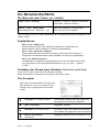
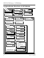
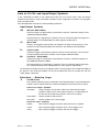
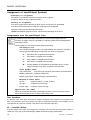
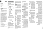
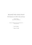
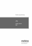
Prozessrechentechnik SS01
Auszug aus dem CIP Tool Manual
Communicating
Interacting
Processes
CIP
CIP Tool 4.01
© 2001 CIP System AG
Contents
Zur Benutzeroberfläche........................................................................ 3
Compositional Structure of CIP Models............................................ 4
SYSTEMS .............................................................................................. 5
SPECIFICATION Browser – SYSTEMS Menu....................... 5
COMMUNICATION SUBNET Editor......................................... 6
CLUSTERS ............................................................................................ 8
SPECIFICATION Browser – CLUSTERS Menu..................... 8
INTERACTION NET Editor.......................................................... 9
PULSE TRANSLATION Editor................................................. 10
MASTER-SLAVE HIERARCHY Editor.................................... 11
MODE SETTING Editor............................................................. 12
INITIALIZATION Editor............................................................... 12
PROCESSES....................................................................................... 13
SPECIFICATION Browser – PROCESSES Menu............... 13
INTERFACE Editor..................................................................... 14
MODES ................................................................................................. 15
SPECIFICATION Browser – MODES Menu.......................... 15
MODE Editor ............................................................................... 16
SWITCH Editor ........................................................................... 19
2
CIP Tool – User Manual
Zur Benutzeroberfläche
Die Maus hat zwei Tasten (ev. virtuell)
selektieren, zuordnen, markieren, umschalten,
Linke Taste: Selektion
verschieben, verbinden, löschen
Menu des selektierten Listenelementes*
Rechte Taste: Objekt-Menu
oder Selektionstaste + Option-Key
(alt )
Menu eines grafischen Objektes
* Das Listenmenu kann auch mit der Selektionstaste im schmalen Menubalken oberhalb einer Liste
aktiviert werden.
PopUp-Menus
Menu einer Objekt-Liste
Mit der Objekttaste wird für das selektierte Listenobjekt ein PopUp-Menu mit
Editierfunktionen aktiviert (Editoren für Attribute und Subobjekte).
Menu eines grafischen Objektes
Mit der Objekttaste wird für das grafische Objekt, welches den Cursor enthält, ein
PopUp-Menu mit Editierfunktionen aktiviert (Editoren für Attribute und Subobjekte).
Menu mit Editierfunktionen
Im Editierfeld von Texteditoren und Textpromptern kann mit der Objekttaste der Maus
ein PopUp-Menu mit den Standard-Editierfunktionen copy, cut, paste, ... geöffnet
werden.
Verändern der Grösse eines Windows (Macintosh-spezifisch)
Cursor auf der unteren rechten Ecke des Windows plazieren;
Objekt-Taste drücken und Window auf die gewünschte Grösse ziehen.
File-Prompter
Beim Laden einer Spezifikation mit <load> oder
beim Sichern mit <save as> erscheint ein FilePrompter, der eine Navigation im File-System
erlaubt.
aufsteigen im Verzeichnis-Baum
Aufwärtspfeil anklicken und in der PopUp-Liste
das gewünschte Verzeichnis selektieren
ganz aufsteigen
Doppelpfeil anklicken
absteigen im Verzeichnis-Baum
Verzeichnis in der Liste selektieren und Abwärtspfeil anklicken oder Doppelclick aufs Verzeichnis.
Default-Verzeichnis
aktualisieren
Doppelpfeil anklicken führt ins Verzeichnis PRT:
CIP Tool – User Manual
3
SPECIFICATION Browser - SYSTEMS Menu
Compositional Structure of CIP Models
SYSTEM
CHANNEL
MESSAGE
channel message
SYSTEM INCLUDE
include text
CIP RECORD
FIELD
record component
CIP DATA TYPE
predefined elementary types
COMMUNICATION NET
graphic model
CHANNEL-PROCESS links
CONSTANT
typed constant
USER TYPE
C type definition (#typedef)
CLUSTER
INTERACTION NET
graphic model
INTERACTION connections
CAST ORDER
sender order
PULSE TRANSLATION
translation tables
OUTPULSE –> INPULSE
MASTER-SLAVE GRAPH
graphic model
hierarchical structure
CLUSTER INCLUDE
include text
PROCESS
PROCESS INCLUDE
include text
VARIABLE
static process variable
STATE
discrete state value
CONDITION
C integer expression
INPORT
MESSAGE
input message
OPERATION
C compound statement
DELAY
C integer expression
OUTPORT
MESSAGE
output message
INQUIRY
C function
INPULSE
input pulse
FUNCTION
C function
OUTPULSE
output pulse
MODE
MODE SETTING
MODE SETTING table
MODE GRAPH
graphic model
state transition graph
SWITCH
allocated CONDITIONS
TIMER, CHAIN, AUTO
PROCESS EXTENSIONS
4
OPERATION ALLOC
allocated OPERATIONS
CIP Tool – User Manual
SPECIFICATION Browser - SYSTEMS Menu
SYSTEMS
SPECIFICATION Browser – SYSTEMS Menu
new
Creates a new system.
All systems are completely independent.
open
Loads a CIP model previously saved as an ASCII file.
You can search for the ASCII file you want in a file prompter.
close
Closes a CIP model without saving it.
Touched CIP models are automatically marked with *.
save
Saves the selected system as an ASCII file.
With <save> the last saving of the system is overwritten. The first saving of
a system is executed with <save as>.
save as
Saves the selected system as an ASCII file.
The directory can be determined in the file prompter which appears. The
suggested file name SystemName.cip can be changed, although this does
not affect the name of the saved system.
CHANNELS
Opens the system’s CHANNEL Editor. The CHANNEL Editor is implemented
as CHANNEL CATEGORY browser. Channel categories are created by the
user to classify the channels of a CIP model.
If a channel of the selected category is selected, the MESSAGES List of the
channel is displayed. In this list you can create, rename and delete
messages. Furthermore, data types can be assigned from a switchable CIP
RECORD / USER TYPES List.
COMMUNICATION Opens the COMMUNICATION SUBNETS List from which you can open the
NET
graphic COMMUNICATION SUBNET Editor.
See COMMUNICATION SUBNET Editor in this section
list invisible
connections
Opens a CHANNEL browser for the sub network which is complementary to
the graphically represented communication nets.
The browser views all channel and process connections which are not
visible in any of the graphic sub networks. For a selected channel, the
writers with their outports and the reader with its inport appear if the
corresponding connections to the channel are not visible in any network.
report
A reporter can be selected in a report prompter to generate a report for the
selected system. The various reporters are specified in work area R .
A report can be generated as a hardcopy (Postscript printer), a Postscript
file, or an ASCII file (graphics suppressed).
CIP Tool – User Manual
5
SYSTEMS - COMMUNICATION NET Editor
COMMUNICATION SUBNET Editor
Graphic process and channel elements are always representations of existing processes or
channels. The user defines which elements are graphically represented.
Meaning of corner marks of process boxes
top left: awaits TIMEUP_ or CHAIN_
top right:
reads channels or AUTO_
bottom right: writes to channels
The selected graphic icon above the graphic edit field determines the current graphic edit function.
Creating graphic elements for P R O C E S S E S
Select the a process in the PROCESSES List of the CLUSTER Browser in the righthand section of the editor (P ).
Place cursor; click.
Creating graphic elements for CHANNELS
Select a channel in the CHANNELS List of the CATEGORY Browser in the right-hand
section of the editor (C ).
Place cursor; click; place label; click.
Remark: In the graphical communication subnets controlled channels are marked in gray.
Erasing graphic elements
Place the cursor on element to be hidden and click.
Erasing a process or a channel in a communication subnet means only that the
component and its connections are no longer visible in that communication subnet. No
communication connections are lost.
If a channel or a connection between a channel and a process is no longer visible in any
network, the channel appears in the Invisible Connections Net, opened from the
SYSTEMS Menu.
Interconnecting channels and processes
Press the selection button within the first element to be connected;
drag the cursor to the second element to be connected and release.
A prompter asks you to select or create an outport or inport.
If a port chosen for the connection is already connected to another channel, the old
connection is lost. Similarly, if a new reader is specified for a channel the connection to
the old reader is lost.
If a connection would be lost which is invisible in the current communication subnet, a
warning is given with a confirmation prompter.
A graphically generated connection is visible in all communication subnets in which the
channel and the connected process are represented.
6
CIP Tool – User Manual
SYSTEMS - COMMUNICATION NET Editor
Clearing directed connections
Press the selection button within the first element;
drag the cursor to the connected element and release.
By clearing a connection you specify that the process and channel concerned are no
longer communicating. The corresponding graphic link is automatically cleared in all
communication subnets.
Selecting
Position the cursor on element to be selected and click the selection button.
Multiple selection
Shift + select, or draw up a selection frame with the selection button held down in
the free edit field.
Moving selected elements
Move mouse with the selection button held down.
PROCESSES / CHANNELS List
The switchable component list in the right-hand section of the editor contains either the processes
or the channels of the system.
P PROCESSES
The PROCESSES List is organized as a browser.
To be able to select a process, you must first select a cluster.
C CHANNEL CATEGORIES
The CHANNELS List is organized as a browser.
To be able to select a channel, you must first select a category.
CIP Tool – User Manual
7
CLUSTERS - CLUSTERS Menu
CLUSTERS
SPECIFICATION Browser – CLUSTERS Menu
new
Creates a new cluster.
A cluster name must be different to all other CIP component names. The
differentiation with respect to system, process and unit names is not casesensitive.
INTERACTION
NET graph
Opens the graphic INTERACTION NET Editor of the cluster.
See INTERACTION NET Editor in this section.
CAST ORDER
For each sender , an associated ordered receivers list allows you to specify
the cast order.
PULSE
Opens the PULSE TRANSLATION Editor of the cluster.
TRANSLATION
INQUIRIES
See PULSE TRANSLATION Editor in this section.
Opens the INQUIRY Editor of the cluster.
See INQUIRY Editor in the PROCESSES section
MASTER-SLAVE
Hierarchy
INITIALIZATION
Opens the graphic MASTER-SLAVE HIERARCHY Editor of the cluster.
See MASTER-SLAVE HIERARCHY Editor in this section
Opens the initialization browser of the cluster.
See INITIALIZATION Editor in this section
Interaction
Trees
Opens the Interaction Tree Viewer of the cluster.
Cascades
Opens the Cascade Viewer of the cluster.
Inverted
Translations
Opens an inverted view to the pulse translations of the cluster.
The translation functions are displayed from the point of view of the
receiver processes.
When you select a RECEIVER and one of its INPULSES, all OUTPULSES
translated to this inpulse are displayed.
report
A reporter can be selected in a report prompter to generate a report for the
selected cluster.
A report can be generated as a hardcopy (postscript printer), a postscript
file, or an ASCII file (graphics suppressed).
8
CIP Tool – User Manual
CLUSTERS - INTERACTION NET Editor
INTERACTION NET Editor
The INTERACTION NET is an architectural model defining the
connections for pulse transmission and state vector inspection
among the processes of a cluster.
Open the INTERACTION NET Editor from the CLUSTERS Menu of the SPECIFICATION Browser with
the <INTERACTION NET graph> command. The INTERACTION NET contains all processes of the
cluster. The graphic process boxes for newly created processes appear in the top left corner of the
graphic editor.
Meaning of corner marks of process boxes
top left: awaits TIMEUP_ , CHAIN_ or AUTO_
top right: reads channels
bottom right:
writes to channels
The selected graphic icon above the graphic edit field determines the current graphic edit function.
Creating directed connections for pulse transmission
Press the selection button within the intended sender process;
drag the cursor to the intended receiver process and release.
Deleting connections
Press the selection button within the intended sender process;
drag the cursor to the intended receiver process and release.
Creating Inspection Connections
Press the selection button within the intended inspected process;
drag the cursor to the intended inspecting process and release.
The inspection (diamond) is created and placed automatically. The arrow indicates
the direction of the data flow.
Deleting Inspection Connections
Press the selection the button within the inspected process;
drag the cursor to the connected insepector and release.
Multiple selection
Shift + select, or draw up a selection frame with the selection button held down in
the free edit field.
Moving selected elements
Move mouse with the selection button held down.
State Vector Inspection
A process can inspect the state vectors of the other processes of the same cluster in its
OPERATIONS, DELAYS, SWITCHES, FUNCTIONS, INQUIRIES and SELECTORS . The required
information is obtained by calling the inquiries (access functions) of those processes.
Inspecting processes must be declared by a graphic inspection connection (diamond) in the
INTERACTION NET. Undeclared inquiry calls will cause compiler errors for the generated code.
CIP Tool – User Manual
9
PULSE TRANSLATION Editor
PULSE TRANSLATION Editor
The interaction net models the pulse flow structure of the
cluster. The transmission of pulses between a sender and a
receiver must finally be specified by logical interlinking of the
sent outpulses with the received inpulses.
Open the PULSE TRANSLATION Editor of a cluster from the CLUSTERS Menu of the Specification
Browser with the <PULSE TRANSLATIONS> command.
PULSE TRANSLATION Editor
For a selected SENDER its set of OUTPULSES is displayed in the TRANSLATIONS List. In the
RECEIVERS List the possible receivers appear. Selecting a RECEIVER opens in the right-hand
section of the editor the corresponding INPULSES List.
The collection of sender/receiver pairs is defined by the interaction net. For every sender/receiver
pair a pulse translation function maps outpulses of the sender into inpulses of the receiver. These
translation functions are defined by means of PULSE TRANSLATION Editors. An outpulse of a
sender can be assigned to precisely one inpulse of a receiver. Not all outpulses of the sender must
be translated in respect of a specific sender/receiver pair. Untranslated outpulses are not
transmitted to the receiver.
A pulse transmission of a sender to a process array may cause several instances of the receiver to
be activated (manycast). Transmissions of this kind can be restricted at instance level by
SELECTORS of the sender (See SELECTOR Assignment Editor).
Specifying a TRANSLATION by assignment:
Pre-select an OUTPULSE.
Pre-select the RECEIVER and an INPULSE
Assign by clicking on the assignment button (<).
The assigned inputs of the selected RECEIVER appear in the TRANSLATIONS List.
Deleting a TRANSLATION :
Pre-select the TRANSLATION to be deleted and click on the deassignment button.
Consistency
PULSE TRANSLATION pairs must be type-compatible. That is, the data type of an outpulse and the
data type of the associated inpulse must be identical, unless the input has no the data type. This
consistency requirement is automatically checked when a model verification is carried out.
10
CIP Tool – User Manual
CLUSTERS - MASTER-SLAVE HIERARCHY Editor
MASTER-SLAVE HIERARCHY Editor
The active mode of a process is determined by the current
states of one or more processes designated as its masters.
Open the MASTER-SLAVE HIERARCHY Editor from the CLUSTERS Menu of the Specification
Browser with the <MASTER-SLAVE Hierarchy > command. The graphical hierarchy editor contains all
processes of the cluster in the top left corner. Processes with several modes are potential slave
processes. Such processes appear with an attached master-slave connector represented as
triangle. The graphic process boxes for newly created processes appear in the top left corner.
The editor allows you to specify the master-slave relation of a cluster. Master-slave associations are
defined by connecting processes by master-slave connectors (triangles). The resulting MASTERSLAVE graph is restricted to be acyclic in order to define a hierarchy relation on the set of processes
of a cluster. (acyclic = 'not containing loops')
Graphic Edit Functions
The selected graphic icon above the graphic edit field determines the current graphic edit function.
Creating a master-slave connection
Press the selection button within the intended master process;
drag the cursor to the intended slave process and release.
If the slave is already connected to a master, a prompter asks you to select the state of
the new master for which the already specified mode setting has to be retained.
A slave process can have at most three masters.
Canceling a master-slave connection
Press the selection button within the master process;
drag the cursor to the connected slave and release.
Multiple selection
Shift + select, or draw up a selection frame with the selection button held down in
the free edit field.
Moving selected elements
Move mouse with the selection button held down.
MASTER-SLAVE CONNECTOR Menu
MODE SETTING
CIP Tool – User Manual
Opens the MODE SETTING Editor for the master slave association defined
by this connector. If the slave has three masters, a sub menu allows you
to choose the guiding master of the MODE SETTING Editor (see below).
11
CLUSTERS - MODE SETTING and INITIALIZATION- Editor
MODE SETTING Editor
Functional MODE SETTING relations define how the active mode
of a slave is determined by the current states of its masters.
Open the MODE SETTING Editor from the graphical connector of the MASTER-SLAVE HIERARCHY Editor or from the PROCESSES Menu of the SPECIFICATION Browser. The layout of the editor
depends on the number of masters of a master-slave association:
Assigning MODES to table fields
Specifying an assignment:
Pre-select a table field and an element of the MODES List at the right hand side of the editor.
Assign by clicking on the assignment button.
Or you can drag a mode label from the MODES List to a table field instead.
Cancelling an assignment:
Pre-select the table field and click on the deassignment button.
INITIALIZATION Editor
The initial state of a cluster is defined by the initial
states, by the initial modes and by the initial variable
values of all processes of the cluster.
Open the INITIALIZATION Editor from the CLUSTERS Menu of the SPECIFICATION Browser with the
<INITIALIZATION > command. For the selected process a double list for mode and state initialization
is opened. If a process has only one mode or state respectively, the corresponding initializiation is
not necessary.
The initial mode and state are defined by selection and execution of the list menu command <set>.
The initial mode and state are marked with i. If a process is slave of one or more master processes,
the initial slave mode is determined by the initial states of the masters.
With <clear> the current initialization is deleted.
12
CIP Tool – User Manual
PROCESSES - PROCESSES Menu
PROCESSES
SPECIFICATION Browser – PROCESSES Menu
new
Creates a new process.
A process name must be different to all other CIP component names. The
differentiation with respect to system, cluster and unit names is not casesensitive.
INTERFACE
Opens the switchable INPUT/OUTPUT List of the process. You can open
editors to assign RECORDS and USER TYPES to messages and pulses.
See INTERFACE Editor in the PROCESSES section.
CONDITIONS
CONDITIONS can be assigned to transitions of non-deterministic branchings
of process modes.
A CONDITION is specified as ANSI C expression. The expression must deliver
an integer value. In ANSI C the value 0 is interpreted as FALSE; all other
values signify TRUE.
Permitted CIP macros:
STATUS (read access to state vector)
IN (Input data)
ID (Index)
Condition assignments are specified in the SWITCH Editor which you open
from the MODES List of the SPECIFICATION Browser.
CONDITIONS can be copied and pasted as components.
ELSE_
The condition list contains always a standard ELSE_ condition which can be
assigned to one transition of a switch. The ELSE_ condition represents the
boolean complement to the conditions assigned to a switch.
DE LA YS
DELAYS are used in processes with specified TIMER EXTENSION for setting
the timer delay.
DELAYS are edited as ANSI C integer expressions. The expression signifies
a duration in TICKS . The duration between two TICKS is defined in the
implementation of the system.
Inquiry calls to other processes are permitted.
Permitted CIP macros:
SELF (write access to state vector)
IN (Input data)
ID (Index)
DELAYS can be copied and pasted as components.
CIP Tool – User Manual
13
PROCESSES - PROCESSES Menu
MODE SETTING Opens the MODE SETTING Editor for this slave process.
See MODE SETTING Editor in the CLUSTERS section.
EXTENSIONS
Opens the process’s EXTENSIONS window. You can mark a number of
options simultaneously:
TIMER
A Process is extended with a timer.
CHAIN
A Process is extended with a feedback mechanism.
AUTO
A Process is extended with an AUTO_ inport which is virtually attached to a
channel containing always an AUTO_ message.
report
A reporter can be selected in a report prompter to generate a report for the
selected process.
A report can be generated as a hardcopy (Postscript printer), a Postscript file,
or an ASCII file (graphics suppressed).
INTERFACE Editor
The interface of a process consists on one hand of a
set of inports and outports which have to be
connected to asynchronous communication
channels, on the other hand of a set of inpulses and
outpulses used to interact synchronously with other
processes of the same cluster.
With the <INTERFACE> menu command you open the switchable I/O-List of a process from the
PROCESSES List of the SPECIFICATION Browser.
The I-List contains the INPULSES-item and the set of user defined INPORTS. The O-List contains
correspondingly the OUTPULSES-item and the set of user defined OUTPORTS. When you select the
INPULSES- or OUTPULSES-item the corresponding PULSES List appears. Selecting an INPORT or an
OUTPORT opens the corresponding MESSAGES List. In the PULSES and MESSAGES Lists you can
create pulses messages and assign USER TYPES or CIP RECORDS from the type list at the right hand
side of the editor.
14
CIP Tool – User Manual
MODES - MODE Editor
MODES
SPECIFICATION Browser – MODES Menu
new
Creates a new MODE.
MODE graph
Opens the graphical editor for the transition structure of the selected mode.
See MODE Editor in this section.
SWITCHES
Opens the SWITCH Editor of the selected mode.
See SWITCH Editor in this section.
OPERATION
Opens the OPERATION Assignment Editor of the selected mode.
See OPERATION Assignment Editor in this section.
assignment
duplicate
Duplicates the selected mode within the process. The duplicate must be
assigned a new name.
report
A reporter can be selected in a report prompter to generate a graphical report
for the selected mode.
CIP Tool – User Manual
15
MODES - MODE Editor
MODE Editor
The graphic editor for the transition structure of a process mode is opened from the PROCESSES
List of the Specification Browser with the <MODE graph> command.
Graphic Edit Functions
With the graphic edit functions you can specify the graphic models of transition structures. The full
model of the state machines is defined by assigning symbols from the STATES and I/O symbol lists.
The selected graphic icon above the graphic edit field determines the current graphic edit function.
Creating process states
Place cursor; click; enter state name; place label; click.
A newly created process state appears also in all theother modes of the process as
graphic element. It is placed in the left top corner of the graphic edit field.
A state is a modelling element belonging to the process.
Creating graphic elements for transitions
Place cursor; click.
Deleting states and transitions
Click on the element to be deleted.
If several graphic elements are selected, all selected elements are deleted.
Creating directed connections
Press the selection button within the first element to be connected;
drag the cursor to the second element to be connected and release.
Canceling connections
Press the selection button within the first element;
drag the cursor to the connected element and release.
Selecting
Position the cursor on element to be selected and press the selection button.
Multiple selection
Shift + select, or draw up a selection frame with the selection button held down
in the free edit field.
Moving selected elements
Move mouse with the selection button held down.
16
CIP Tool – User Manual
MODES - MODE Editor
Lists of STATES and Input/Output Symbols
In the switchable list editor at the right-hand section you can create states, input and output
symbols of the process. Input and output symbols can be assigned to transitions of the graphic
state transition model.
The selected button activates the corresponding symbol list:
Input/Output Symbols
>M
INPORT M E S S A G E S
Inport messages are delivered by asynchronous channels, attached to inports in the
COMMUNICATION NET Editor.
The INPORTS List is organized as a browser. You can create the inport messages for a
selected INPORT in the MESSAGES List which appears underneath it.
>P
INPULSES
Inpulses are triggered synchronously by outpulses of other cluster processes. The
senders must be interconnected to the receiver in the INTERACTION NET Editor.
P>
OUTPULSES
Outpulses trigger synchronously inpulses of other cluster processes. The receivers
must be interconnected to the senders in the INTERACTION NET Editor.
M>
OUTPORT MESSAGES
Outport messages are released to asynchronous channels, attached to outports in
the COMMUNICATION NET Editor.
The OUTPORTS List is organized as a browser. You can create the outport messages
for a selected OUTPORT in the MESSAGES List which appears underneath it.
CIP RECORDS and USER TYPES are assigned to pulses and messages in the INTERFACE Editor of
the process. The INTERFACE Editor can be accessed directly from the symbol lists with the
<open editor> command.
Extensions – Modeling Sugar
X
EXTENSIONS
The symbols appearing in the list depend on the selected options in the EXTENSIONS
window, which is opened with the <choose EXTENSION> command in the list menu:
Extension Output Symbols
Output symbol to set the timer. When you select the SET TIMER
symbol the DELAYS List of the process appears (see description of
the DELAYS command of the process menu in this section).
SET TIMER
STOP TIMER
Output symbol to stop the timer.
SET CHAIN
Output symbol to set a chain trigger.
Extension Input Symbols
TIMEUP_
Input symbol to trigger transitions when the timer has expired.
CHAIN_
Input symbol to trigger transitions when a chain trigger is set.
AUTO_
Input symbol to trigger transitions with the auto trigger.
CIP Tool – User Manual
17
MODES - MODE Editor
Assignment of Input/Output Symbols
Specifying an assignment:
Pre-select a transition box and the list symbols to be assigned.
Assign by clicking on the assignment button.
Deleting an assignment:
The open assignment list determines which type of assignment can be deleted.
Pre-select the transition box for which the assignment is to be deleted.
Delete by clicking on the deassignment button.
special: EXTENSION symbols must be selected correspondingly in the X-List
Assignments from the Input/Output Lists
A symbol from the MESSAGES, INPULSES or X-List must be assigned to each
transition as trigger. Output is specified by assigning symbols from the MESSAGES,
INPULSES or X-List.
The four fields of a transition have the following meaning:
Info Field (top field)
The transition number issued by the Tool identifies the transition. The letters
occurring in the field indicate assignments not visible in the graphic:
O–
Operations are assigned to the transition.
T–
SET TIMER is assigned to the transition.
S–
STOP TIMER is assigned to the transition.
C–
SET CHAIN is assigned to the transition.
W – Invisible WRITES are specified for the transition; that is, several
output messages have been assigned to the transition.
Three Symbol Fields
Top symbol field:
input message or inpulse (interaction or communication)
Middle symbol field: outpulse (interaction)
Bottom symbol field: output message (communication)
Meaning of corner marks
top left:
assigned TIMEUP_ ,CHAIN_ or AUTO_
top right:
assigned input message
bottom right:
assigned output message
Special case: SET TIMER
When you assign the SET TIMER symbol from the X-List, you must also pre-select a
DELAY from the DELAYS List, so that the timer delay is set.
Port Numbers
If a process owns more than one inport or outport, contiguous port numbers are assigned to the
ports. Port numbers are used to qualify messages assigned to transitions. Port numbers can be
changed with the <shift up> and the <shift down> command of the port lists.
W – Invisible Writes
If several output messages are assigned to a transition, the one with the lowest port number is
visible only. The pop up info utility displays hidden outport messages automatically.
18
CIP Tool – User Manual
MODES - SWITCH Editor
SWITCH Editor
If several state transitions with a common initial state can be
triggered by the same input, the reaction of the state machine is
not determined. In order to make the execution of the state
machine deterministic, mutually exclusive conditions have to be
assigned to all transitions of a non-deterministic branching. A
branching with assigned conditions is termed SWITCH.
Open the SWITCH Editor of a mode from the MODES List of the Specification Browser using the
<SWITCHES> command. The SWITCH Editor can also be opened from the graphical MODE Editor: In
the menu of a graphical state, the command SWITCHES is enabled, if the state is origin of a nondeterministic branching (state marked in gray).
SWITCH Editor
The SWITCH Editor allows you to assign conditions to the transitions of non-deterministic
branchings. Conditions are defined as ANSI C expressions in the CONDITION Editor of the process.
A branching with assigned conditions is termed switch. A switch is identified by a state-input pair.
The SWITCH Editor is correspondingly realized as a browser on state-input pairs. If you select a
state-input pair, the transition number and the poststate of the transitions of the switch are
displayed in the middle list.
If the MODE Editor is open, you can use the graphic transition model to navigate in the SWITCH
Editor: Select a non-deterministic graphic state (marked in gray) and activate <SWITCHES> of the
state menu to select the corresponding branching in the SWITCH Editor.
At the right hand side of the editor the conditions list of the process is displayed. This list contains
always a standard ELSE_ condition which can be assigned to one transition of a switch. The ELSE_
condition represents the boolean complement to the conditions assigned to a switch.
Assigning CONDITIONS to the TRANSITIONS of a SWITCH :
Pre-select a transition and a condition. Assign by clicking on the assignment button.
The assigned conditions appear in the TRANSITION List.
An assignment is deleted with the deassignment button as usual.
Remark: The CONDITIONS of a SWITCH should be mutually exclusive.
19
CIP Tool – User Manual