1
Allen-Bradley
AIC+ Advanced
Interface
Converter
(Cat. No. 1761-NET-AIC)
User
Manual
Important User
Information
Because of the variety of uses for the products described in this
publication, those responsible for the application and use of this
control equipment must satisfy themselves that all necessary steps
have been taken to assure that each application and use meets all
performance and safety requirements, including any applicable laws,
regulations, codes and standards.
The illustrations, charts, sample programs and layout examples
shown in this guide are intended solely for purposes of example.
Since there are many variables and requirements associated with any
particular installation, Allen-Bradley does not assume responsibility
or liability (to include intellectual property liability) for actual use
based upon the examples shown in this publication.
Allen-Bradley publication SGI-1.1, Safety Guidelines for the
Application, Installation, and Maintenance of Solid-State Control
(available from your local Allen-Bradley office), describes some
important differences between solid-state equipment and
electromechanical devices that should be taken into consideration
when applying products such as those described in this publication.
Reproduction of the contents of this copyrighted publication, in
whole or in part, without written permission of Allen-Bradley
Company, Inc., is prohibited.
Throughout this manual we use notes to make you aware of safety
considerations:
!
ATTENTION: Identifies information about practices
or circumstances that can lead to personal injury or
death, property damage or economic loss.
Attention statements help you to:
• identify a hazard
• avoid the hazard
• recognize the consequences
Important:
Identifies information that is critical for successful
application and understanding of the product.
SLC, SLC 5/01, SLC 5/02, SLC 5/03, SLC 5/04, SLC 5/05, MicroLogix, Data Highway/Data Highway Plus and Encompass
are trademarks; PLC is a registered trademark of Rockwell Automation. Belden is a trademark of Belden, Inc.
Preface
Who Should Use this Manual . . . . . . . . . . . . . . . . . . . . . . . . . . . .
Purpose of this Manual . . . . . . . . . . . . . . . . . . . . . . . . . . . . . . . . .
Contents of this Manual . . . . . . . . . . . . . . . . . . . . . . . . . . . . . .
Related Documentation . . . . . . . . . . . . . . . . . . . . . . . . . . . . . .
Common Techniques Used in this Manual . . . . . . . . . . . . . . . . . . .
Allen–Bradley Support . . . . . . . . . . . . . . . . . . . . . . . . . . . . . . . . .
Local Product Support . . . . . . . . . . . . . . . . . . . . . . . . . . . . . . .
Technical Product Assistance . . . . . . . . . . . . . . . . . . . . . . . . . .
Your Questions or Comments on this Manual . . . . . . . . . . . . . . .
P–1
P–1
P–2
P–2
P–3
P–3
P–3
P–3
P–3
Chapter 1
Description . . . . . . . . . . . . . . . . . . . . . . . . . . . . . . . . . . . . . . . . .
Operating Modes . . . . . . . . . . . . . . . . . . . . . . . . . . . . . . . . . . . . .
Device Compatibility . . . . . . . . . . . . . . . . . . . . . . . . . . . . . . . . . .
Node Address Identification . . . . . . . . . . . . . . . . . . . . . . . . . . .
1–1
1–1
1–2
1–2
Chapter 2
Compliance to European Union Directives . . . . . . . . . . . . . . . . . . .
2–1
EMC Directive . . . . . . . . . . . . . . . . . . . . . . . . . . . . . . . . . . . . .
2–1
Low Voltage Directive . . . . . . . . . . . . . . . . . . . . . . . . . . . . . . . .
2–1
Safety Considerations . . . . . . . . . . . . . . . . . . . . . . . . . . . . . . . . .
2–2
Mounting . . . . . . . . . . . . . . . . . . . . . . . . . . . . . . . . . . . . . . . . . . .
2–2
DIN Rail Mounting . . . . . . . . . . . . . . . . . . . . . . . . . . . . . . . . . .
2–2
Installation . . . . . . . . . . . . . . . . . . . . . . . . . . . . . . . . . . . . . .
2–2
Removal . . . . . . . . . . . . . . . . . . . . . . . . . . . . . . . . . . . . . . .
2–3
Panel Mounting . . . . . . . . . . . . . . . . . . . . . . . . . . . . . . . . . . . .
2–3
Template . . . . . . . . . . . . . . . . . . . . . . . . . . . . . . . . . . . . . . .
2–3
Installation . . . . . . . . . . . . . . . . . . . . . . . . . . . . . . . . . . . . . .
2–3
Wiring . . . . . . . . . . . . . . . . . . . . . . . . . . . . . . . . . . . . . . . . . . . . .
2–4
Power Supply Wiring . . . . . . . . . . . . . . . . . . . . . . . . . . . . . . . .
2–4
Network Port Wiring . . . . . . . . . . . . . . . . . . . . . . . . . . . . . . . . .
2–4
Attaching the DH-485/DF1 Connector to the Communication Cable 2–5
Grounding and Terminating the DH-485/DF1 Network . . . . . . .
2–6
Cable Selection Guide . . . . . . . . . . . . . . . . . . . . . . . . . . . . . . . . .
2–7
Reference Drawing . . . . . . . . . . . . . . . . . . . . . . . . . . . . . . . . .
2–7
Selection Guide . . . . . . . . . . . . . . . . . . . . . . . . . . . . . . . . . . . .
2–8
Recommended User Supplied Components.E . . . . . . . . . . . . . . . . 2–10
Publication 1761-6.4
ii
Table of Contents
Chapter 3
Network Diagrams.B . . . . . . . . . . . . . . . . . . . . . . . . . . . . . . . . . .
Point-to-Point Isolator.C . . . . . . . . . . . . . . . . . . . . . . . . . . . . . .
Components Replaced by the AIC+.D . . . . . . . . . . . . . . . . . . .
DH-485 Network with SLC 5/03 and SLC 5/04 Processors and a PC
DH-485 Network with a MicroLogix 1000 Controller . . . . . . . . . .
Typical 3-Node OEM Network . . . . . . . . . . . . . . . . . . . . . . . . . .
Networked Operator Interface Device and MicroLogix Controller .
Networks Using “Ganged” Converters . . . . . . . . . . . . . . . . . . . .
Extending Network to 2,438 Meters (8,000 Feet).E . . . . . . . . . .
DF1 Master-Slave Network with Modem.F . . . . . . . . . . . . . . . .
Avoid Incorrect Connections . . . . . . . . . . . . . . . . . . . . . . . . . . .
3–1
3–1
3–2
3–3
3–4
3–4
3–5
3–6
3–7
3–8
3–9
Chapter 4
Diagnostics . . . . . . . . . . . . . . . . . . . . . . . . . . . . . . . . . . . . . . . . .
4–1
Appendix A
Physical Specifications . . . . . . . . . . . . . . . . . . . . . . . . . . . . . . .
Hardware Handshaking.H . . . . . . . . . . . . . . . . . . . . . . . . . . . .
Auto Transmit Delay (turn around time) Per Baud Rate.I . . . . . . .
Publication 1761-6.4
A–1
A–1
A–2
Read this preface to familiarize yourself with the rest of the manual.
This preface covers the following topics:
• who should use this manual
• the purpose of this manual
• conventions used in this manual
• Allen–Bradley support
Who Should Use this
Manual
Use this manual if you are responsible for designing, installing,
programming, or troubleshooting control systems that use
Allen–Bradley small logic controllers.
You should have a basic understanding of MicroLogixt products.
You should understand programmable controllers and be able to
interpret the ladder logic instructions required to control your
application. If you do not, contact your local Allen–Bradley
representative for information on available training courses before
using this product.
Purpose of this Manual
This manual is a reference guide for the Advanced Interface
Converter (AIC+).
This manual:
• gives you an overview of the AIC+ operation
• explains the procedures you need to install and wire the AIC+
Contents of this Manual
Chapter
Title
Contents
Preface
Describes the purpose, background, and scope of
this manual. Also specifies the audience for whom
this manual is intended.
1
Product Overview
Explains and illustrates the theory behind the AIC+
operation. Covers hardware and software features.
2
Installation and Wiring
Provides installation procedures and wiring
guidelines.
3
Network Connections
Provides guidelines for connecting to a network.
4
Troubleshooting
Explains how to interpret and correct problems with
your AIC+.
Specifications
Provides physical, electrical, environmental, and
functional specifications for the AIC+.
Appendix A
Publication 1761-6.4
P–2
Related Documentation
The following documents contain additional information concerning
Allen–Bradley SLCt, PLCR and MicroLogixt products. To obtain
a copy, contact your local Allen–Bradley office or distributor.
For
Setting up a DH-485 network
DF1 protocol
Read this Document
Document
Number
SLC 500 Modular Hardware Style Installation and Operation Manual
1747-6.2
MicroLogix 1000 Programmable Controllers User Manual
1761-6.3
SLC 500 Modular Hardware Style Installation and Operation Manual
1747-6.2
Data Highway/Data Highway Plust Station Connector Installation Data
1770-6.2.2
Data Highway/DH+/DH-485 Communication Protocol and Command Set Reference Manual
1770-6.5.16
MicroLogix 1000 Controllers
MicroLogix 1000 Programmable Controllers User Manual
1761-6.3
SLC 500 Processors
SLC 500 Modular Hardware Style Installation and Operation Manual
1747-6.2
Recommended third party
devices
Rockwell Automation Encompasst Product Directory (The Americas)
6873
Cable wiring techniques
Industrial Automation Wiring and Grounding Guidelines
1770-4.1
A complete listing of current
Allen–Bradley documentation,
including ordering instructions.
Also indicates whether the
documents are available on
CD-ROM or in multi-languages.
Allen–Bradley Publication Index
SD499
A glossary of industrial
automation terms and
abbreviations
Allen–Bradley Industrial Automation Glossary
AG-7.1
Publication 1761-6.4
P–3
Common Techniques Used in
this Manual
"
Allen–Bradley Support
The following conventions are used throughout this manual:
• Bulleted lists such as this one provide information, not procedural
steps.
• Numbered lists provide sequential steps or hierarchical
information.
• Italic type is used for emphasis.
We also use this convention to call attention to helpful information.
Allen–Bradley offers support services worldwide, with over 75
Sales/Support Offices, 512 authorized Distributors and 260
authorized Systems Integrators located throughout the United States
alone, plus Allen-Bradley representatives in every major country in
the world.
Local Product Support
Contact your local Allen-Bradley representative for:
• sales and order support
• product technical training
• warranty support
• support service agreements
Technical Product Assistance
If you need to contact Allen-Bradley for technical assistance, please
review the information in the Troubleshooting chapter first. Then
call your local Allen-Bradley representative.
Your Questions or Comments on this Manual
If you find a problem with this manual, please notify us of it on the
enclosed Publication Problem Report.
If you have any suggestions for how this manual could be made
more useful to you, please contact us at the address below:
Allen-Bradley Company, Inc.
Control and Information Group
Technical Communication, Dept. A602V, T122
P.O. Box 2086
Milwaukee, WI 53201–2086
Publication 1761-6.4
P–4
Publication 1761-6.4
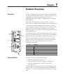
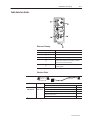
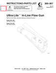
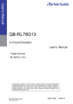
Description
The AIC+ advanced interface converter provides a communication
link between various networked devices. Ports 1, 2, and 3 are used
for making the communication connections. The AIC+ is
compatible with a variety of SLCt and MicroLogixt controllers
and peripherals.
MicroLogix controllers provide power to the AIC+ via port 2’s
cable. However, if a MicroLogix controller is not connected to port
2, a 24V dc power supply connected to the converter’s external
power terminals is required. The DC power source selector switch
needs to be set for your particular configuration. See Network
Diagrams on pages 3–1 through 3–9 for more details on how to wire
and configure the AIC+.
The baud rate selector switch is used to match the baud rate filter of
the AIC+ to the network baud rate. This switch does not change the
network baud rate and is normally left in the AUTO position. In
high noise environments, the baud rate selector switch should be
taken out of the AUTO mode and set to the same baud rate as the
network. See Auto Transmit Delay on page A–2 for more
information on baud rates.
Item
Description
Port 1 – DB-9 RS-232, DTE
Port 2 – mini-DIN 8 RS-232
Port 3 – RS-485 Phoenix plug
DC Power Source selector switch
Baud Rate Filter selector switch
Terminals for external 24V dc power supply and chassis ground
Operating Modes
The AIC+ can be used in the following modes:
• point-to-point isolator (see page 3–1)
• RS-232 to RS-485 isolator (see pages 3–2 through 3–8)
• RS-232 to half-duplex “user mode” ASCII isolator
(see page 3–8)
Communication is established using hardware handshaking or auto
transmit signals. For more information on hardware handshaking,
see page A–1. For more information on auto transmitting, see page
A–2.
1–2
Product Overview
Device Compatibility
The AIC+ can be used to interconnect the following devices:
•
•
•
•
•
•
SLC 500t, 5/01t, 5/02t, and 5/03t processors (channel 1)
SLC 5/03, 5/04t, and 5/05t processors (channel 0)
MicroLogix 1000 controllers
Operator interface devices
PC serial ports (or any 9-pin DTE serial port)
Modems
Note: The 1761-HHP-B30 Hand-Held Programmer is not
connectable to the AIC+ advanced interface converter.
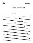
Node Address Identification
There is no node
address associated
with the network port
(Port 3).
Port 1 Node Address
(The node address
is configured in the
device connected to
Port 1.)
Publication1761-6.4
Port 2 Node Address
(The node address is
configured in the device
connected to Port 2.)
Use this write-on area
to mark the node address
of each connection.
Compliance to European
Union Directives
If this product has the CE mark it is approved for installation within
the European Union and EEA regions. It has been designed and
tested to meet the following directives.
EMC Directive
This product is tested to meet Council Directive 89/336/EEC
Electromagnetic Compatibility (EMC) and the following standards,
in whole or in part, documented in a technical construction file:
• EN 50081-2
EMC – Generic Emission Standard, Part 2 – Industrial
Environment
• EN 50082-2
EMC – Generic Immunity Standard, Part 2 – Industrial
Environment
This product is intended for use in an industrial environment.
Low Voltage Directive
This product is tested to meet Council Directive 73/23/EEC
Low Voltage, by applying the safety requirements of EN 61131–2
Programmable Controllers, Part 2 – Equipment Requirements and
Tests.
For specific information required by EN 61131-2, see the appropriate
sections in this publication, as well as the following Allen-Bradley
publications:
• Industrial Automation Wiring and Grounding Guidelines For
Noise Immunity, publication 1770-4.1
• Guidelines for Handling Lithium Batteries, publication AG-5.4
• Automation Systems Catalog, publication B111
Publication1761-6.4
2–2
Installation and Wiring
Safety Considerations
This equipment is suitable for use in Class I, Division 2, Groups A,
B, C, D, or non-hazardous locations only.
ATTENTION: Explosion Hazard
•Substitution of components may impair suitability for
Class I, Division 2.
•Do not replace components or disconnect equipment
unless power is switched off and the area is known to
be non-hazardous.
•Do not connect or disconnect connectors or operate
switches while circuit is live unless the area is known
to be non-hazardous.
•This product must be installed in an enclosure. All
cables connected to the product must remain in the
enclosure or be protected by conduit or other means.
•AIC+ must be operated from an external power
source.
!
Use only the following communication cables and replacement
connectors in Class I, Division 2, Hazardous Locations.
Environment Classification
Class I, Division 2 Hazardous
Environment
Communication Cables
1761-CBL-PM02 (Series C or later)
1761-CBL-HM02 (Series C or later)
1761-CBL-AM00 (Series C or later)
1761-CBL-AP00 (Series C or later)
2707-NC8 (Series B)
2707-NC9 (Series B)
2707-NC10 (Series B)
2707-NC11 (Series B)
1746-RT30 AIC+ Connector
Mounting
The AIC+ can be mounted in the vertical or horizontal position.
There are no spacing requirements except as necessary for DIN rail
latch movement. See page A–1 for operating temperature
specification.
Side
View
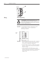
DIN Rail Mounting
DIN
Rail
Installation
1. Mount your DIN rail.
2. Snap the DIN rail latch into the closed position.
latch
Publication1761-6.4
Installation and Wiring
2–3
3. Hook the top slot over the DIN rail.
4. While pressing the AIC+ against the rail, snap the AIC+ into
position.
Removal
1. Place a screwdriver in the DIN rail latch at the bottom of the
AIC+.
2. Holding the AIC+, pry downward on the latch until the AIC+ is
released from the DIN rail.
DIN
Rail
Side
View
Panel Mounting
Installation
1. Remove the mounting template from page A–3 of this document.
2. Secure the template to the mounting surface.
3. Drill holes through the template.
4. Remove the mounting template.
5. Mount the AIC+.
Publication1761-6.4
2–4
Installation and Wiring
Mounting
Template
Wiring
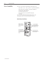
Power Supply Wiring
!
Important:
Bottom
View
ATTENTION: EXPLOSION HAZARD - An external
power supply must be used in Class I, Division 2
applications and the DC Power Source selector switch
must be in the EXTERNAL position before connecting
the power supply to the AIC+
In non-hazardous locations, external power is not
required if the AIC+ port 2 is connected to a
MicroLogix controller.
24VDC
DC
NEUT
CHS
GND
Important:
S Some devices provide power to the AIC+ via port 2’s
cable. The DC power source selector switch needs
to be set for your particular configuration.
S If you are using a 1746-P1 or 1746-P2 power supply,
the AIC+ is the only device that can be connected to
that power supply.
S Always connect the CHS GND (chassis ground)
terminal to the nearest earth ground. This connection
must be made whether or not an external 24V dc
supply is used.
Publication1761-6.4
Installation and Wiring
2–5
Network Port Wiring
Use these instructions for wiring Beldent cable. If you are using
standard Allen-Bradley cables, see the Cable Selection Guide on
page 2–7.
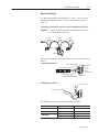
Attaching the RS-485 Connector to the Communication Cable
Important:
A daisy-chained network is recommended. We do not
recommend the following:
Belden
#3106A or
#9842
Belden
#3106A or
#9842
Belden
#3106A or
#9842
Connector
Connector
Connector
Incorrect
Attach the connector to the Belden #3106A or #9842 cable as shown
below.
Single Cable Connection
Orange with White Stripes
6 Termination
5
A
4
B
3 Common
2 Shield
1 Chassis Ground
White with Orange Stripes
Shrink Tubing
Recommended
Blue (#3106A) or
Blue with White Stripes (#9842)
Multiple Cable Connection
Drain Wire
to Previous Device
to Successive Device
The table below shows connections for Belden #3106A.
For this Wire/Pair
Connect this Wire
To this Terminal
Shield/Drain
Non-jacketed
Terminal 2 – Shield
Blue
Blue
Terminal 3 – (Common)
White/Orange
White with Orange Stripe
Orange with White Stripe
Terminal 4 – (Data B)
Terminal 5 – (Data A)
Publication1761-6.4
2–6
Installation and Wiring
The table below shows connections for Belden #9842.
For this Wire/Pair
Connect this Wire
Shield/Drain
Blue/White
White/Orange
To this Terminal
Non-jacketed
Terminal 2 – Shield
White with Blue Stripe
Blue with White Stripe
Cut back – no connection➀
Terminal 3 – (Common)
White with Orange Stripe
Terminal 4 – (Data B)
Orange with White Stripe
Terminal 5 – (Data A)
➀ To prevent confusion when installing the communication cable, cut back the white with blue stripe
wire immediately after the the insulation jacket is removed. This wire is not used by DH-485.
Grounding and Terminating the RS-485 Network
Only one connector at the end of the link must have Terminals 1 and
2 jumpered together. This provides an earth ground connection for
the shield of the communication cable.
Both ends of the network must have Terminals 5 and 6 jumpered
together. This connects the termination impedance (of 120Ω) that is
built into each AIC and AIC+ as required by the RS-485
specification.
End-of-Line Termination
Jumper
Jumper
Belden #3106A or #9842 Cable
1219 m (4000 ft) Maximum
Jumper
Publication1761-6.4
Installation and Wiring
2–7
Cable Selection Guide
Reference Drawing
Item
Description
Port 1 – Isolated DB-9 RS-232, DTE
Port 2 – Isolated Mini-DIN 8 RS-232
Port 3 – RS-485 Phoenix plug
DC Power Source selecter switch
(cable = port 2 power source, external = external
power source connected to item 5)
Terminals for external 24V dc power supply and
chassis ground
Selection Guide
1747-CP3
1761-CBL-AC00
Cable
Length
Connections
from
1747-CP3
1761-CBL-AC00
3m (9.8 ft)
45 cm (17.7 in)
to AIC+
SLC 5/03 or SLC 5/04 processor, channel 0
port 1
PC COM port
port 1
PanelView 550 through NULL modem adapter
port 1
➀
DTAM Plus / DTAMt Micro
port 1
Port 1 on another AIC+
➀ Requires a male-to-male gender changer.
port 1
Publication1761-6.4
2–8
Installation and Wiring
1761-CBL-AS09
1761-CBL-AS03
Cable
Length
Connections
from
1761-CBL-AS03
1761-CBL-AS09
3m (9.8 ft)
9.9m (29.5 ft)
to AIC+
SLC 500 Fixed, SLC 5/01, SLC 5/02, and SLC 5/03 processors
port 3
PanelView 550 RJ45 port
port 3
1761-CBL-HM02➁
1761-CBL-AM00
Cable
Length
Connections
from
1761-CBL-AM00
45 cm (17.7 in)
➁ 2m (6.5 ft)
1761-CBL-HM02
to AIC+
port 2
no
cable
to port 2 on another AIC+
port 2
yes
external
1761-CBL-PM02➁
Length
Connections
from
1761-CBL-AP00
45 cm (17.7 in)
➁ 2m (6.5 ft)
1761-CBL-PM02
Selection
Switch
etting
Setting
MicroLogix 1000
1761-CBL-AP00
Cable
External
Power
uppl
Supply
Required
to AIC+
External
Power
Supply
uppl
Required
Selection
Switch
Setting
etting
yes
external
SLC 5/03 or SLC 5/04 processors, channel 0
port 2
MicroLogix 1000
port 1
PanelView 550 through NULL modem adapter
port 2
yes
external
➀
DTAM Plus / DTAM Micro
port 2
yes
external
PC COM port
port 2
yes
external
not applicable
➂
user supplied cable
Cable
Length
Connections
from
straight 9–25 pin
––
modem or other communication device
to AIC+
port 1
➀ Requires a male-to-male gender changer.
➁ Series B cables are required for hardware handshaking.
➂ External power supply is required unless the AIC+ is powered by a MicroLogix controller connected to port 2
with a 1761-CBL-AM00 or 1761-CBL-HM02 or equivalent cable.
Publication1761-6.4
Installation and Wiring
Recommended User
Supplied Components
2–9
These components can be purchased from your local electronics
supplier.
Component
Recommended Model
external power supply and chassis
ground
power supply rated for 20.4–28.8V dc
NULL modem adapter
standard AT
radio modem
model MDS 9310, no hardware handshaking (Refer
to Pyramid Integrator Solution Product Directory,
publication PSP 5.1)
straight 9–25 pin RS-232 cable
see table below for port information if making own
cables
1761-CBL-AP00 or 1761-CBL-PM02
DB-9 RS-232
Port 1
DH-485 connector
Port 3
cable straight D connector
Port 2
6 78
3
4
5
12
➀
Port 1
DB-9 RS-232
Port 2
(1761-CBL-PM02 cable)
received line signal detector
(DCD)
same state as port 1’s DCD
signal
chassis ground
received data (RxD)
received data (RxD)
cable shield
transmitted data (TxD)
transmitted data (TxD)
signal ground
DTE ready (DTR)
DTE ready (DTR)
DH-485 data B
signal common (GRD)
signal common (GRD)
DH-485 data A
DCE ready (DSR)
DCE ready (DSR)
termination
request to send (RTS)
request to send (RTS)
not applicable
clear to send (CTS)
clear to send (CTS)
not applicable
not applicable
not applicable
not applicable
Item
Port 3
DH-485 Connector
➀ An 8-pin mini DIN connector is used for making connections to port 2. This connector is not
commercially available. If you are making a cable to connect to port 2, you must configure your
cable to connect to the Allen-Bradley cable shown above.
Publication1761-6.4
2–10
Installation and Wiring
Publication1761-6.4
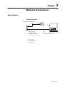
Network Connections
Network Diagrams
Point-to-Point Isolator
1761-CBL-AM00 or 1761-CBL-HM02
MicroLogix
1000
PC
APS
AIC+
24V dc
(Not needed in this
configuration since the
MicroLogix 1000 provides
power to the AIC+ via port 2.)
1747-CP3 or 1761-CBL-AC00
DB-9 RS-232 port
mini-DIN 8 RS-232 port
DH-485/DF1 port
Publication1761-6.4
3–2
Network Connections
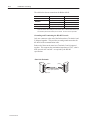
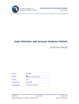
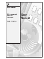
Components Replaced by the AIC+
The AIC+ replaces the combination of a 1747-PIC interface
converter and 1747-AIC isolated link coupler in most applications.
SLC 5/04 processor
Previous DH-485
Network
24V dc power
1747-PIC
Interface
Converter
1747-AIC
1747-AIC
1747-AIC
SLC 5/02 processor
SLC 5/03 processor
SLC 5/04 processor
Today’s DH-485 Network
using the AIC+
24V dc power
AIC+
1747-AIC
1747-AIC
SLC 5/02 processor
DB-9 RS-232 port
mini-DIN 8 RS-232 port
DH-485/DF1 port
Publication1761-6.4
SLC 5/03 processor
Network Connections
3–3
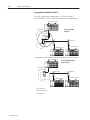
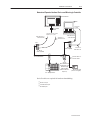
DH-485 Network with SLC 5/03 and SLC 5/04 Processors
and a PC
SLC 5/03 or SLC 5/04
processor
PC
APS
PC to port 1
or port 2
24V dc power
connection from processor
channel 0 to port 1 or port 2
1761-CBL-AP00
or
1747-CP3
1761-CBL-PM02
or
1761-CBL-AC00
1761-CBL-AP00
or
1761-CBL-PM02
AIC+
AIC+
1747-CP3
or
1761-CBL-AC00
24V dc
(user
supplied)
1747-AIC
1747-AIC
SLC DH-485 Network
SLC 5/02 processor
SLC 5/03 processor
Series B cables are required for hardware handshaking.
DB-9 RS-232 port
mini-DIN 8 RS-232 port
DH-485/DF1 port
Publication1761-6.4
3–4
Network Connections
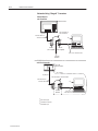
DH-485 Network with a MicroLogix 1000 Controller
PC
MicroLogix 1000 (Series C or higher)
APS
1761-CBL-AM00 or
1761-CBL-HM02
AIC+
PC to port 1
or port 2
connection from
port 1 or port 2
to MicroLogix
1761-CBL-AP00 or
1761-CBL-PM02
1761-CBL-AP00 or
1761-CBL-PM02
AIC+
24V dc
(user supply needed
if using port 1 on AIC+)
24V dc
(user supplied)
MicroLogix DH-485 Network
1747-CP3 or
1761-CBL-AC00
Typical 3-Node OEM Network
PanelViewt 550
MicroLogix 1000
(Series C or higher)
1761-CBL-AM00 or
1761-CBL-HM02
RJ45 port
AIC+
1761-CBL-AS09 or
1761-CBL-AS03
3-Node Network
(not expandable)
PC
APS
24V dc
(Not needed in this
configuration since the
MicroLogix 1000
provides power to the
AIC+ via port 2.)
1747-CP3 or 1761-CBL-AC00
Series B cables are required for hardware handshaking.
DB-9 RS-232 port
mini-DIN 8 RS-232 port
DH-485/DF1 port
Publication1761-6.4
Network Connections
3–5
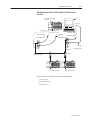
Networked Operator Interface Device and MicroLogix Controller
PanelView 550
PC
APS
PC to port 1
or port 2
RS-232 port
NULL modem
adapter
connection from NULL modem
adapter to port 1 or port 2
1761-CBL-AP00 or
1761-CBL-PM02
1761-CBL-AP00 or
1761-CBL-PM02
1747-CP3 or
1761-CBL-AC00
AIC+
AIC+
24V dc
(user supplied)
1747-CP3 or
1761-CBL-AC00
24V dc
(user supplied)
1747-AIC
SLC DH-485 Network
AIC+
24V dc
(Not needed in this
configuration since
the MicroLogix
1000 provides
power to the AIC+
via port 2.)
1761-CBL-AM00 or
1761-CBL-HM02
MicroLogix 1000
(Series C or higher)
SLC 5/03 processor
Series B cables are required for hardware handshaking.
DB-9 RS-232 port
mini-DIN 8 RS-232 port
DH-485/DF1 port
Publication1761-6.4
3–6
Network Connections
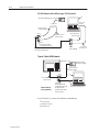
Networks Using “Ganged” Converters
DH-485 Network
with PanelView
PanelView 550
1761-CBL-AM00 or
1761-CBL-HM02
RJ45 port
1761-CBL-AS09 or
1761-CBL-AS03
AIC+
24V dc
(user supplied)
APS
PC
AIC+
24V dc
(user supplied)
1747-CP3 or 1761-CBL-AC00
DH-485
Network
DH-485 Network
with Fixed Controller
SLC 500
fixed controller
24V dc power
RJ45 port
1761-CBL-AM00 or 1761-CBL-HM02
1761-CBL-AS09 or
1761-CBL-AS03
AIC+
DH-485
Network
DB-9 RS-232 port
mini-DIN 8 RS-232 port
DH-485/DF1 port
Publication1761-6.4
PC
AIC+
1747-CP3 or
1761-CBL-AC00
APS
Network Connections
3–7
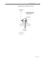
Extending Network to 2,438 Meters (8,000 Feet)
DH-485 Network
1,219m (4,000 ft)
maximum
Extended DH-485 Network
maximum of 2,438m (8,000 ft)
and 32 nodes total
1761-CBL-AM00 or
1761-CBL-HM02
AIC+
24V dc
(user supplied or
from 24V dc terminals
on SLC controller)
AIC+
24V dc
(user supplied or
from 24V dc terminals
on SLC controller)
DH-485 Network
1,219m (4,000 ft)
maximum
DB-9 RS-232 port
mini-DIN 8 RS-232 port
DH-485/DF1 port
Publication1761-6.4
3–8
Network Connections
DF1 Master-Slave Network with Modem
SLC 5/03 processor
SLC 5/03 processor
DF1
Master
CH0
radio modem
or lease line
AIC+
DF1
Slave
1761-CBL-AP00 or
1761-CBL-PM02
CH0
1761-CBL-AP00 or
1761-CBL-PM02
AIC+
straight 9–25 pin cable
straight
9–25
pin cable
SLC 5/03 processor
SLC 5/03 processor
radio modem
or lease line
CH0 to port 1 or port 2
DF1
1761-CBL-AP00
Slave
or 1761-CBL-PM02
1747-CP3
or 1761-CBL-AC00
AIC+
Important:
CH0 to port 1 or port 2
DF1
1761-CBL-AP00
Slave
or 1761-CBL-PM02
1747-CP3
or 1761-CBL-AC00
Use this diagram for “user mode” ASCII as well as DF1
master-slave protocol. See page A–1 (in Specifications)
for more information on hardware handshaking and
communication protocols.
Hardware handshaking requires Series B cables.
DB-9 RS-232 port
mini-DIN 8 RS-232 port
DH-485/DF1 port
Publication1761-6.4
AIC+
Network Connections
3–9
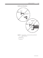
Avoid Incorrect Connections
1747-AIC
DH-485
Network
1761-CBL-AS09 or
1761-CBL-AS03
AIC+
1761-CBL-AS09 or
1761-CBL-AS03
1747-AIC
DH-485
Network
SLC 5/03 processor
Important:
Do not do this— the cable will fit, but will NOT
function properly.
DB-9 RS-232 port
mini-DIN 8 RS-232 port
DH-485/DF1 port
Publication1761-6.4
3–10
Network Connections
Publication1761-6.4
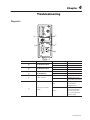
Troubleshooting
Diagnostics
Item
Indicator
TX RS-232 9-pin (port 1)
TX RS-232 8-pin (port 2)
TX RS-485 (port 3)
PWR – Power OK
Condition
flashing
off
flashing
off
flashing
off
on
off
cable
Power Source Selection
Switch
external
Indicates
transmitting
receiving or idle
transmitting
receiving or idle
transmitting
receiving or idle
power OK
no power to AIC+ or DC
source switch set incorrectly
24V dc power supplied to
AIC+ from device
connected to port 2
24V dc power supplied to
AIC+ from external source
(use 24V dc power from
SLC or user-supplied 24V
dc power supply)
Publication1761-6.4
4–2
Troubleshooting
Publication1761-6.4
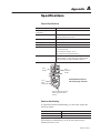
Physical Specifications
Description
Specification
24V dc Power Source
Requirement
20.4 – 28.8V dc
Current Draw
0 – 120 mA
200 mA maximum inrush current
Internal Isolation (see below)
500V dc
Operating Ambient Temperature
–0 to 60_C (32 to 140_F)
Storage Temperature
–40 to 85_C (–40 to 175_F)
Agency Certification
UL 1604
C-UL C22.2 No. 213
Class I Division 2 Groups A, B, C, D
CE compliant for all applicable directives
DH-485, DF1, or “user” Network
maximum number of nodes = 32 per multidrop network
maximum length = 1,219m (4,000 ft) per multidrop network
maximum number of “ganged” multidrop networks = 2
Port 3
RS-485
Port 2
mini-DIN 8
RS-232
Isolation Between All Ports
and Power Supply Terminals
Port 1
DB-9
RS-232 DTE
Terminals for External 24V dc
Power Supply and Chassis
Ground
Hardware Handshaking
To implement hardware handshaking, use cables that support the
following signals.
Signal Definition
Function
RTS active
an input to AIC+ port
CTS active
an output from AIC+ port
When hardware handshaking is used, the auto transmit delay
(turnaround time) is zero.
Publication 1761-6.4
A–2
Specifications
Protocol
AIC+ Support of Hardware Handshaking
DF1 full duplex (point-to-point
isolator)
yes
DF1 Master-Slave
no
“user mode” ASCII
yes
➀
➀ Any communication coming off of the RS-485 line (port 3) will not drive the handshaking lines on
ports 1 and 2. Devices on ports 1 and 2 can drive the other RS-232 ports handshaking lines and
the RS-485 transmitters.
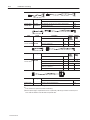
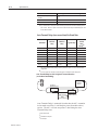
Auto Transmit Delay (turn around time) Per Baud Rate
Baud Rate
Minimum
Delay
Maximum
Delay
Pre-Send
Transmit
Delay
Typical Delay
600
7.3 ms
15.0 ms
10.8 ms
Setting
16 ms
1200
7.3 ms
15.0 ms
10.8 ms
16 ms
2400
5.5 ms
11.2 ms
8.1 ms
12 ms
4800
2.7 ms
5.7 ms
4.0 ms
6 ms
9600
1.3 ms
2.8 ms
2.0 ms
3 ms
14400
0.9 ms
1.9 ms
1.4 ms
2 ms
19200
0.6 ms
1.4 ms
1.0 ms
2 ms
AUTO
0.3 ms
0.7 ms
0.5 ms
➁
➀
➀ The pre-send transmit delay setting is used in your device’s (SLC, PLC, etc.) communications
configuration.
➁ Use a pre-send value from above, depending upon the network baud rate being used.
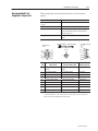
Auto Transmit Delay for AIC+ Using Auto Transmit Detection
(no hardware handshaking)
AIC+
Packet to
Network Device
Network
Device
Packet from
Auto Transmit Network Device
Delay
(turn around time)
Auto Transmit Delay is measured from the time the AIC+ transmits
its last mark out of Port 3, until the delay time (from table above)
expires. The AIC+ will not accept Port 3 data during the Auto
Transmit Delay time.
DB-9 RS-232 port
mini-DIN 8 RS-232 port
RS-485 port
Publication 1761-6.4
Specifications
A–3
Mounting Template
52.07 mm
(2.05 in)
118 mm
(4.64 in)
107 mm
(4.20 in)
27.7 mm
(1.09 in)
allow 15 mm (0.6 in) clearance
for DIN rail latch movement during
installation and removal
Publication 1761-6.4
A–4
Specifications
Publication 1761-6.4
**$,/ #*$6 "-,1 "1(,& %-/ 00(01 ,"$ " !*$ 0$*$"1(-, &2(#$ /$%$/$,"$ #/ 4(,& 0$*$"1(-, &2(#$ "-+. 1(!(*(16 "-,1 "1(,& **$,/ #*$6 %-/
00(01 ,"$ "-,1$,10 -% + ,2 * #$3("$ "-+. 1(!(*(16 / (* +-2,1(,& (,01 ** 1(-, /$+-3 * 2/-.$ , ,(-, (/$"1(3$
-+.*( ,"$ (/$"1(3$ -4 -*1 &$ (/$"1(3$ + ,2 *0 /$* 1$# +-#$0 -.$/ 1(,& +-2,1(,& / (* +-2,1(,& ,$14-/) #( &/ +0 3-(# (,"-//$"1 "-,,$"1(-,0 "-+.-,$,10 /$.* "$ !6 1'$ ,$14-/) 4(1'
("/--&(5 "-,1/-**$/ ,$14-/) 4(1' ,# ./-$00-/0 ,#
$51$,#(,& 1'$ ,$14-/) + 01$/0* 3$ ,$14-/) 4(1'
+-#$+ ,$14-/)$# -.$/ 1-/ (,1$/% "$
#$3("$ ,# ("/--&(5
"-,1/-**$/ ,$14-/)0 20(,& & ,&$#
"-,3$/1$/0 .-(,11-.-(,1 (0-* 1-/ 16.(" * ,-#$ ,$14-/)
,$14-/) .-/1 4(/(,& 11 "'(,& "-,,$"1-/ 1"-++2,(" 1(-, " !*$ &/-2,#(,& ,# 1$/+(, 1(,& 1'$
,$14-/) ,-#$ ##/$00 (#$,1(%(" 1(-, -.$/ 1(,& +-#$0 . ,$* +-2,1(,& (,01 ** 1(-, .-4$/ 02..*6 4(/(,& ./-#2"1 -3$/3($4 .2!*(" 1(-,0 /$* 1$# /$"-++$,#$# 20$/ 02..*($#
"-+.-,$,10 0 %$16 "-,0(#$/ 1(-,0 Publication 1761-6.4
I–2
Index
Publication 1761-6.4
I–3
Publication 1761-6.4
Allen-Bradley, a Rockwell Automation Business, has been helping its customers improve productivity and quality for more than 90 years. We design, manufacture and support a broad range
of automation products worldwide. They include logic processors, power and motion control
devices, operator interfaces, sensors and a variety of software. Rockwell is one of the world’s
leading technology companies.
Worldwide representation.
Argentina • Australia • Austria • Bahrain • Belgium • Brazil • Bulgaria • Canada • Chile • China, PRC • Colombia • Costa Rica • Croatia • Cyprus • Czech Republic • Denmark
• Ecuador • Egypt • El Salvador • Finland • France • Germany • Greece • Guatemala • Honduras • Hong Kong • Hungary • Iceland • India • Indonesia • Ireland • Israel • Italy
• Jamaica • Japan • Jordan • Korea • Kuwait • Lebanon • Malaysia • Mexico • Netherlands • New Zealand • Norway • Pakistan • Peru • Philippines • Poland • Portugal •
Puerto Rico • Qatar • Romania • Russia–CIS • Saudi Arabia • Singapore • Slovakia • Slovenia • South Africa, Republic • Spain • Sweden • Switzerland • Taiwan • Thailand •
Turkey • United Arab Emirates • United Kingdom • United States • Uruguay • Venezuela • Yugoslavia
Allen-Bradley Headquarters, 1201 South Second Street, Milwaukee, WI 53204 USA, Tel: (1) 414 382-2000 Fax: (1) 414 382-4444
Publication 1761-6.4 – April 1998
E1998 Rockwell International Corporation. All rights reserved. Printed in USA