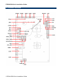
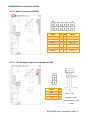
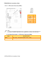
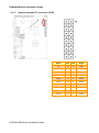
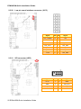
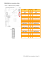
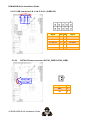
1
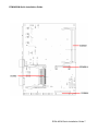
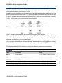
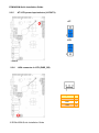
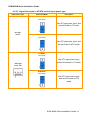
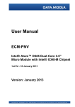
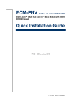
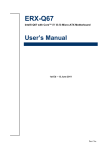
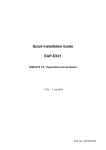
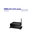
ECM-A50M 3.5” AMD eOntario Module Quick Installation Guide 2nd Ed – 3 March 2012 Part No. E2017351801R ECM-A50M Quick Installation Guide FCC Statement THIS DEVICE COMPLIES WITH PART 15 FCC RULES. OPERATION IS SUBJECT TO THE FOLLOWING TWO CONDITIONS: (1) THIS DEVICE MAY NOT CAUSE HARMFUL INTERFERENCE. (2) THIS DEVICE MUST ACCEPT ANY INTERFERENCE RECEIVED INCLUDING INTERFERENCE THAT MAY CAUSE UNDESIRED OPERATION. THIS EQUIPMENT HAS BEEN TESTED AND FOUND TO COMPLY WITH THE LIMITS FOR A CLASS "A" DIGITAL DEVICE, PURSUANT TO PART 15 OF THE FCC RULES. THESE LIMITS ARE DESIGNED TO PROVIDE REASONABLE PROTECTION AGAINST HARMFUL INTERFERENCE WHEN THE EQUIPMENT IS OPERATED IN A COMMERCIAL ENVIRONMENT. THIS EQUIPMENT GENERATES, USES, AND CAN RADIATE RADIO FREQUENCY ENERGY AND, IF NOT INSTALLED AND USED IN ACCORDANCE WITH THE INSTRUCTION MANUAL, MAY CAUSE HARMFUL INTERFERENCE TO RADIO COMMUNICATIONS. OPERATION OF THIS EQUIPMENT IN A RESIDENTIAL AREA IS LIKELY TO CAUSE HARMFUL INTERFERENCE IN WHICH CASE THE USER WILL BE REQUIRED TO CORRECT THE INTERFERENCE AT HIS OWN EXPENSE. Copyright Notice Copyright 2012 Avalue Technology Inc., ALL RIGHTS RESERVED. No part of this document may be reproduced, copied, translated, or transmitted in any form or by any means, electronic or mechanical, for any purpose, without the prior written permission of the original manufacturer. A Message to the Customer Avalue Customer Services Each and every Avalue’s product is built to the most exacting specifications to ensure reliable performance in the harsh and demanding conditions typical of industrial environments. Whether your new Avalue device is destined for the laboratory or the factory floor, you can be assured that your product will provide the reliability and ease of operation for which the name Avalue has come to be known. Your satisfaction is our primary concern. Here is a guide to Avalue’s customer services. To ensure you get the full benefit of our services, please follow the instructions below carefully. Technical Support We want you to get the maximum performance from your products. So if you run into technical difficulties, we are here to help. For the most frequently asked questions, you can easily find answers in your product documentation. These answers are normally a lot more detailed than the ones we can give over the phone. So please consult the user’s manual 2 ECM-A50M Quick Installation Guide ECM-A50M Quick Installation Guide first. To receive the latest version of the user’s manual; please visit our Web site at: http://www.avalue.com.tw/ If you still cannot find the answer, gather all the information or questions that apply to your problem, and with the product close at hand, call your dealer. Our dealers are well trained and ready to give you the support you need to get the most from your Avalue’s products. In fact, most problems reported are minor and are able to be easily solved over the phone. In addition, free technical support is available from Avalue’s engineers every business day. We are always ready to give advice on application requirements or specific information on the installation and operation of any of our products. Please do not hesitate to call or e-mail us. Headquarters and Branch Avalue Technology Inc. Avalue USA Avalue Technology Inc. 7F, 228, Lian-cheng Road, Chung Ho City, Taipei, 9 Timber Lane, Marlboro, NJ 07746-1443 Taiwan Tel: (732) 414-6500 Tel:+886-2-8226-2345 Fax: (732) 414-6501 Fax: +886-2-8226-2777 Information: [email protected] Information:[email protected] Service: [email protected] Service: [email protected] BCM Advanced Research BCM Advanced Research an Avalue Company Avalue Europe 7 Marconi, Irvine, CA92618 Aalsgaarde, Denmark Tel: +1-949-470-1888 Tel: +45-7025-0310 Fax: +1-949-470-0971 Fax:+45-4975-5026 Information: [email protected] Information: [email protected] Web: www.bcmcom.com Service: [email protected] Avalue China Avalue Japan Avalue Technology Inc. Avalue Technology Inc. Room 805, Building 9,No.99 Tianzhou Rd., Avalue Europe A/S Moelledalen 22C, 3140 2F keduka-Bldg, 2-27-3 Taito, Caohejing Development Area, Xuhui District, Shanghai Taito-Ku, Tokyo 110-0016 Japan Tel: +86-21-5169-3609 Tel: +81-3-5807-2321 Fax:+86-21-5445-3266 Fax: +81-3-5807-2322 Information: [email protected] Service: [email protected] Information: [email protected] Service: [email protected] ECM-A50M Quick Installation Guide 3 ECM-A50M Quick Installation Guide 1. Getting Started 1.1 Safety Precautions Warning! Always completely disconnect the power cord from your chassis whenever you work with the hardware. Do not make connections while the power is on. Sensitive electronic components can be damaged by sudden power surges. Only experienced electronics personnel should open the PC chassis. Caution! Always ground yourself to remove any static charge before touching the CPU card. Modern electronic devices are very sensitive to static electric charges. As a safety precaution, use a grounding wrist strap at all times. Place all electronic components in a static-dissipative surface or static-shielded bag when they are not in the chassis. Always note that improper disassembling action could cause damage to the motherboard. We suggest not removing the heatsink without correct instructions in any circumstance. If you really have to do this, please contact us for further support. 1.2 Packing List Before you begin installing your single board, please make sure that the following materials have been shipped: 1 x 3.5” ECM-A50M Micro Module 1 x Quick Installation Guide for ECM-A50M 1 x DVD-ROM contains the followings: — User’s Manual (this manual in PDF file) — Ethernet driver and utilities — VGA drivers and utilities — Audio drivers and utilities 1 x Cable set contains the followings: — — — — — 1 x Audio cable (12pin, 2.0mm pitch) 1 x USB cable (10P/2.54mm-10P/2.0mm) 1 x Serial ATA cable (7-pin, standard) 1 x Serial ATA cable (15-pin, 2P/2.0mm) 1 x Flat Cable 9P(M)-Dupont 10P/2.0mm 17cm 4 x D-sub Jack Screws DIP AUX-032 A1 W/Audio/4USB 4 ECM-A50M Quick Installation Guide ECM-A50M Quick Installation Guide 2. Hardware Configuration ECM-A50M Quick Installation Guide 5 ECM-A50M Quick Installation Guide 2.1 Product Overview 6 ECM-A50M Quick Installation Guide ECM-A50M Quick Installation Guide ECM-A50M Quick Installation Guide 7 ECM-A50M Quick Installation Guide 2.2 Jumper and Connector List You can configure your board to match the needs of your application by setting jumpers. A jumper is the simplest kind of electric switch. It consists of two metal pins and a small metal clip (often protected by a plastic cover) that slides over the pins to connect them. To “close” a jumper you connect the pins with the clip. To “open” a jumper you remove the clip. Sometimes a jumper will have three pins, labeled 1, 2, and 3. In this case, you would connect either two pins. The jumper settings are schematically depicted in this manual as follows: A pair of needle-nose pliers may be helpful when working with jumpers. Connectors on the board are linked to external devices such as hard disk drives, a keyboard, or floppy drives. In addition, the board has a number of jumpers that allow you to configure your system to suit your application. If you have any doubts about the best hardware configuration for your application, contact your local distributor or sales representative before you make any changes. The following tables list the function of each of the board’s jumpers and connectors. Jumpers Label Function Note JBAT1 Clear CMOS 3 x 1 header, pitch 2.00 mm JRI1 Serial port 1 (COM1) signal selector 3 x 2 header, pitch 2.0 mm JRI2 Serial port 2 (COM2) signal selector 3 x 2 header, pitch 2.0 mm JAT/ATX AT/ ATX power Input selector 3 x 1 header, pitch 2.0 mm JDEEPS5 ErP power saving mode selector 2 x 1 header, pitch 2.0 mm JTSEL Touch Selector 2 x 1 header, pitch 2.0 mm 8 ECM-A50M Quick Installation Guide ECM-A50M Quick Installation Guide Connectors Label Function Note BAT-WB Battery connector 2 x 1 wafer, pitch 1.25 mm COM1 Serial port 1 connector D-sub 9-pin, male CFCARD CF card connector CPU_FAN1 CPU fan connector 4 x 1 wafer DCIN Power connector 2 x 2 wafer, pitch 4.2 mm FLED1 LED connector HDMI HDMI connector 19 pin J422/485 Serial port 1 in RS-422/485 mode 3 x 2 header, pitch 2.0 mm JAUDIO Audio connector 6 x 2 header, pitch 2.0 mm JBKL LCD inverter connector 5 x 1 wafer, pitch 2.0 mm JCOM2 Serial port 2 connector 5 x 2 header, pitch 2.0 mm JDIO General purpose I/O connector 10 x 2 header, pitch 2.0 mm JFP Miscellaneous setting connector 5 x 2 header, pitch 2.0 mm JKBMS Keyboard & Mouse connector 4 x 2 header, pitch 2.0 mm JLPC Low pin count interface connector 7 x 2 header, pitch 2.0 mm JLVDS LVDS connector 20 x 2 header, pitch 2.0 mm JSPI SPI connector 4 x 2 header, pitch 2.0 mm JTOUCH Touch Connector 9 X 1 wafer box, pitch 2.00 mm JUSB1 USB connector 0 & 1 5 x 2 header, pitch 2.0 mm JUSB2 USB connector 4 & 5 5 x 2 header, pitch 2.0 mm JUSB3 USB connector 2 & 3 5 x 2 header, pitch 2.0 mm JVR LCD backlight brightness adjustment 3 x 1 header, pitch 2.54 mm LAN1/ LAN2 RJ-45 Ethernet connector PCIEMINI Mini PCI express connector PCIEMINI-H Mini PCI express latch PWR_SB +V5A connector in ATX 3 x 1 wafer, pitch 2.54 mm SATA1_PWR SATA1 power connector 2 x 1 wafer, pitch 2.0 mm SATA2_PWR SATA2 power connector 2 x 1 wafer, pitch 2.0 mm SATA1 Serial ATA connector 1 SATA2 Serial ATA connector 2 SODIMM 204-pin DDR3 SODIMM connector USB USB connector 6 VGA VGA connector 52 pin D-sub 15-pin, female ECM-A50M Quick Installation Guide 9 ECM-A50M Quick Installation Guide 2.3 Setting Jumpers & Connectors 2.3.1 Clear CMOS (JBAT1) Protect* Clear CMOS * Default 2.3.2 Serial port 1 (COM1) signal selector (JRI1) +5V Ring* +12V * Default 10 ECM-A50M Quick Installation Guide ECM-A50M Quick Installation Guide 2.3.3 Serial port 2 (COM2) signal selector (JRI2) +5V Ring* +12V * Default 2.3.4 Power connector (DCIN) Signal PIN PIN Signal GND 2 4 VIN=12V GND 1 3 VIN=12V ECM-A50M Quick Installation Guide 11 ECM-A50M Quick Installation Guide 2.3.5 AT/ ATX power Input selector (JAT/ATX) AT* ATX * Default 2.3.6 +V5A connector in ATX (PWR_SB) 12 ECM-A50M Quick Installation Guide Signal PIN PSON 1 GND 2 +V5A 3 ECM-A50M Quick Installation Guide 2.3.6.1 Signal Description –AT/ATX mode & Input power type Input power type Power-ON Mode Description AT Mode (JAT/ATX) Use AT type power input, and set the board in AT mode. AT Type (DCIN) ATX Mode (JAT/ATX) Use AT type power input, and set the board in ATX mode. AT Mode (JAT/ATX) Use ATX type power input, and set the board in AT mode. ATX Type (PWR_SB) ATX Mode (JAT/ATX) Use ATX type power input, and set the board in ATX mode. ECM-A50M Quick Installation Guide 13 ECM-A50M Quick Installation Guide 2.3.7 ErP Power saving mode selector (JDEEPS5) DEEPS5=0* DEEPS5=1 Signal PIN DEEPS5_SEL 1 GND 2 * Default 2.3.7.1 ErP Power saving mode selector setting details Settings Description DEEPS5=0 System will not enter deep S5 state after AC power on, it remains in normal ACPI S5 state. DEEPS5=1 System will enter deep S5 state 6 sec after AC power on. 14 ECM-A50M Quick Installation Guide ECM-A50M Quick Installation Guide 2.3.8 Touch selector (JTSEL) 4/8W* 5W JTOUCH * Default 2.3.9 4-WIRE 5-WIRE Signal PIN CSENSE 2 CY- 1 8-WIRE (5~8) (4~8) (1~8) 1 N/A N/A Right Sense 2 N/A N/A Left Sense 3 N/A N/A Bottom Sense 4 N/A Sense Top Sense 5 Right LR Right Excite 6 Left LL Left Excite 7 Bottom UR Bottom Excite 8 Top UL Top Excite 9 GND GND GND Battery connector (BAT-WB) Signal PIN VBAT 1 GND 2 ECM-A50M Quick Installation Guide 15 ECM-A50M Quick Installation Guide 2.3.10 CPU fan connector (CPU_FAN) Signal PIN GND 1 +V12S 2 SIO_FANI 3 SIO_FANO 4 2.3.11 Serial port 1 in RS-422/485 mode (J422/485) Signal 16 ECM-A50M Quick Installation Guide PIN PIN Signal GND 6 5 +V5S 422_RXDP 4 3 485-422_TXDP 422_RXDN 2 1 485-422_TXDN ECM-A50M Quick Installation Guide 2.3.12 Audio connector (JAUDIO) Signal PIN PIN Signal GND 12 11 MIC1_JD LIN1_JD 10 9 FRONT_JD MIC1_L 8 7 MIC1_R LIN1_L 6 5 LIN1_R GND 4 3 GND FRONT_L 2 1 FRONT_R 2.3.13 LCD backlight brightness adjustment (JVR) Signal PIN GND 3 LVDS_BLKT_CTRL 2 +5V 1 Variation Resistor (Recommended: 4.7KΩ, >1/16W) ECM-A50M Quick Installation Guide 17 ECM-A50M Quick Installation Guide 2.3.14 LCD Inverter Connector (JBKL) Signal PIN +5V 5 BRIADJ 4 BKLEN 3 GND 2 +12V 1 Note: For inverters with adjustable Backlight function, it is possible to control the LCD brightness through the VR signal controlled by JVR. Please see the JVR section for detailed circuitry information. 2.3.14.1Signal Description – LCD Inverter Connector (JBKL) Signal Signal Description BRIADJ Vadj = 0.75V ~ 4.25V (Recommended: 4.7KΩ, >1/16W) BKLEN LCD backlight ON/OFF control signal 18 ECM-A50M Quick Installation Guide ECM-A50M Quick Installation Guide 2.3.15 Serial port 2 connector (JCOM2) Signal PIN PIN Signal DCD 1 2 RXD TXD 3 4 DTR 6 DSR GND RTS 7 8 CTS RI2 9 10 NC 2.3.16 Touch connector (JTOUCH) Signal PIN 4-Wire 5-Wire 8-Wire TGND 9 GND GND GND CY- 8 Top UL Top Excite CY+ 7 Bottom UR Bottom Excite CX- 6 Left LL Left Excite CX+ 5 Right LR Right Excite CSENSE 4 NA Sense Top Sense CY+ 3 NA NA Bottom Sense CX- 2 NA NA Left Sense CX+ 1 NA NA Right Sense ECM-A50M Quick Installation Guide 19 ECM-A50M Quick Installation Guide 2.3.17 General purpose I/O connector (JDIO) 20 ECM-A50M Quick Installation Guide Signal PIN PIN Signal +5V 20 19 GND SMB_DATA_S 18 17 SMB_CLK_S GP17 16 15 GP27 GP16 14 13 GP26 GP15 12 11 GP25 GP14 10 9 GP24 GP13 8 7 GP23 GP12 6 5 GP22 GP11 4 3 GP21 GP10 2 1 GP20 ECM-A50M Quick Installation Guide 2.3.18 2.3.19 Miscellaneous setting connector (JFP) Signal PIN PIN Signal GND 10 9 CASEOPEN# +3.3V 8 7 HD_LED# PWR_LED# 6 5 3.3V GND 4 3 SYS_RST# GND 2 1 EXT_PWRBTN# PIN PIN Signal 7 NC Keyboard & Mouse connector (JKBMS) Signal MS_CLK# 6 5 MS_DAT# +VCC_KB 4 3 GND KB_CLK# 2 1 KB_DAT# ECM-A50M Quick Installation Guide 21 ECM-A50M Quick Installation Guide 2.3.20 Low pin count interface connector (JLPC) Signal 2.3.21 PIN PIN Signal LPC_LDRQ# 14 13 +5V GND 12 11 +5V GND 10 9 LPC_SERIRQ CLK_JLPC 8 7 LPC_AD3 LPC_FRAME# 6 5 LPC_AD2 A_RST# 4 3 LPC_AD1 +3.3V 2 1 LPC_AD0 SPI connector (JSPI) 22 ECM-A50M Quick Installation Guide Signal PIN PIN Signal +3.3V 1 2 GND CS# 3 4 SPI_CLK DI_R 5 6 SPI_DO HOLD# 7 ECM-A50M Quick Installation Guide 2.3.22 LVDS connector (JLVDS) Signal PIN PIN Signal +12V 39 40 +12V GND 37 38 GND LVDSB_CLK# 35 36 LVDSA_CLK# LVDSB_CLK 33 34 LVDSA_CLK GND 31 32 GND LVDSB_DATA3# 29 30 LVDSB_DATA2# LVDSB_DATA3 27 28 LVDSB_DATA2 GND 25 26 GND LVDSB_DATA1# 23 24 LVDSB_DATA0# LVDSB_DATA1 21 22 LVDSB_DATA0 GND 19 20 GND LVDSA_DATA3# 17 18 LVDSA_DATA2# LVDSA_DATA3 15 16 LVDSA_DATA2 GND 13 14 GND LVDSA_DATA1# 11 12 LVDSA_DATA0# LVDSA_DATA1 9 10 LVDSA_DATA0 GND 7 8 GND LVDS_DDC_CLK 5 6 LVDS_DDC_DATA +3.3V 3 4 +5V +3.3V 1 2 +5V ECM-A50M Quick Installation Guide 23 ECM-A50M Quick Installation Guide 2.3.23 USB connector 0 & 1/ 4 & 5/ 2 & 3 (JUSB1/2/3) JUSB1 JUSB2 JUSB3 Signal 2.3.24 PIN PIN Signal +5V 1 2 GND N1/ N3/ N5 3 4 GND P1/ P3/ P5 5 6 P0/ P2/P4 GND 7 8 N0/ N2/N4 GND 9 10 +5V SATA1/2 Power connector (SATA1_PWR/ SATA2_PWR) SATA2_PWR SATA1_PWR 24 ECM-A50M Quick Installation Guide Signal PIN GND 1 +5V 2