1
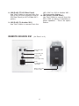
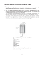
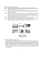
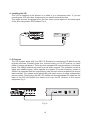
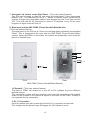
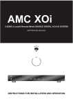
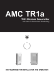
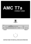
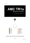
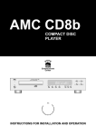
APPLICATION AND FEATURE LIST
Features of the AMCTM model XOi
* System for total 4 Zones
* System with 8 Sources
4 Local / 4 Remote mixed Sources.
* Only RJ45 & Speaker Wires used for installations from XOi main unit to all zones
* Two ways AMC propriotary Digital Data Communication System between XOi main
unit and keypads in all zones
* Designed with cascade feature for keypad XK1
* Volume Control & Tone Control for each Zone
* Four 38KHz and four 56KHz IR outputs on rear panel of XOi main unit
* Doorbell and telephone mute system (PDM1) - option
* With RS232 to digital link with other systems - option
* IR remote control receiver on each zone for controlling XOi main unit and remote
Sources in other zones
* RCA, 3.5mm mini jack and RJ45 Remote Source input jacks in each Zone
* Low profile 1U
* Power of each channel / zone : 15W x 2 Digital Amplifiers for each Zone.
* The XOi package contains:
1 XOi main unit
4 IRE1 IR emitters with feedback LED
1 Remote Control Handset
1 This Manual
1 Zone description labels
* Options : XK1, XS1, XU1, PDM1 (numbers of XK1, XS1, XU1, PDM1 required based
on each installation designs)
2
REAR PANEL CONNECTIONS/FRONT PANEL CONTROLS
8
1
2
Front
3
54
6
9
7
10
Rear
Doorbells 1 & 2
Tel Lines 1 & 2
AMC PDM1
(Phone-Doorbell-Mute Module)
Zone 1
Zone 2
Zone 3
1. Local Source Inputs 1~4
2. IR Out - 38KHz
3. IR Out - 56KHz
4. Mute
5. Link
6. Status
Zone 4
7. 12VDC
8. Keypads & Remote Sources
9. Speaker Terminals
10. RS232
11. AC input receptacle with Fuse
FRONT PANEL
1
2
1. Power Switch (Standby / Off) &
Blue LED
2. Zone LED & 4 square Recesses
3
11
REAR PANEL CONNECTIONS
1. Local Source Inputs 1~4
Each of these stereo RCA inputs
receives an audio signal from up to
four independent audio sources.
Remarks: There are other 4 Remote
sources from Zone 1~4 as Remote
Source Inputs R5 to R8 can be
selected by all zones.
Remote Source R5 is located at
XS1 of Zone 1, Remote Source R6
is located at XS1 of Zone 2, Remote
Source R7 is located at XS1 of Zone
3 and Remote Source R8 is located
at XS1 of Zone 4. Signals of R5 are
mixed with signals of Local Source 1,
Signals of R6 are mixed with signals
of Local Source 2, Signals of R7 are
mixed with signals of Local Source 3
and Signals of R8 are mixed with
signals of Local Source 4. Users can
connect Source unit to one of the
two mixed source inputs or connect
two Source units to both Local and
Remote Source Inputs. When users
connect two Source units to both
Local and Remote Source Inputs,
users can play each source
separately or play both sources at
the same time with signals of the two
sources mixed together.
3. IR Out - 56KHz
For cable and satellite boxes
4. Mute
This 3.5mm non-shorting Stereo
connector (Power, Mute, Gnd) is
designed to be used in conjunction
with the AMC PDM1 (Phone-DoorbellMute Module) - This is an option
feature.
5. Link
This 3.5mm mono connection is used
to expand the AMC XOi from four to
eight zones. - This is an option feature.
6. Status
This 3.5mm mono connection provides
a +12VDC output when a zone is
turned on. This can be used to trigger
external equipments.
7. 12VDC
For supplying 12VDC to external
modules. (total 1A max)
8. Keypads & Remote Sources
9. Speaker Terminals
10. RS232
This is used for making interface with
other system and for factory purposes.
- This is an option feature.
2. IR Out - 38KHz
For most Audio Sources
11. AC input receptacle with Fuse
FRONT PANEL CONTROLS
1. Power Switch (Standby / Off) & Blue LED
The Power Switch turns AMC XOi "Standby" or "Off"
The Blue LED will be lit up during "Standby", will be turned off during "Off"
2. Zone LED & 4 square Recesses
Each of these LEDs indicates, when lit, that its zone keypads are turned on.
The 4 square recesses are for putting labels of names of all zones
4
KEYPAD
(XK1 for Zone 1 to 4)
6
1
10
7
9
8
5
2
(JK2)
TO XOi
Rear Panel
4
or JK3 of
Main XK1
3
1. LED's of Volume Level of the zone
Volume-only one LED will be lighted
up. (for energy saving purposes)
2. Volume up
6. Source Selection
The 8 source buttons independently
select any of the four local sources (
Source 1 to 4) connected to the rear
panel of AMC XOi main unit and four
Remote Sources (Source R5 to R8)
connected to the XU1 of Zone 1 to 4.
(R5 located at Zone 1, R6 located at
Zone 2, R7 located at Zone 3 and R8
located at Zone 4) The selected source
button will remain lit.
/ down
3. IR Receiver
Each keypad has an IR receiver for
controlling the Local and Remote
source equipments.
4. Power
The power button turns the keypad's
z o n e o n a n d o f f i n d e p e n d e n t l y.
Pressing and holding the power button
turns all zones off simultaneously(the
all zone features is option).
7. JK1 (RJ45) (to XS1) (Zone 1~4) or
XU1 (Zone 5~8) or Power Amp (Zone
5~8)
For Zone 1~4, please use Cat-5 cable
to connect from the JK1 of XK1 to the
RJ45 connector on the rear side of
XS1 for hooking to Remote Sources
R5 (located at Zone 1), R6 (located at
Zone 2), R7 (located at Zone 3) and
R8 (located at Zone 4).
5. Mute
The mute button temporarily mutes any
audio playing in that keypad's zone.
5
8. JK2 (RJ45) (TO XOi Rear Panel)
Use Cat-5 cable to connect from the
JK2 of XK1 to RJ45 of specific Zone on
XOi Rear Panel (or JK3 of Main XK1 option)
JK3 of XK1 to JK2 of Another XK1. This is an option feature.
10. JK4 (RJ45) (To SUB ZONE)
Use Cat-5 cable to connect from the
JK4 of XK1 to main-in of amplifiers or
power speakers. - This is an option
feature.
9. JK3 (RJ45) (To Another XK1)
Use Cat-5 cable to connect from the
REMOTE SOURCE XS1
(for Zone 1 to 4)
RCA Jack Inputs
(L & R)
3.5mm Mini Jack
Inputs (L & R)
IR Output
(3.5mm Mini Jack)
RJ45
(L & R Inputs and
IR Output)
RJ45 to JK1 of XK1
via Cat-5 Cable
6
REMOTE CONTROL
1
2
3
4
1. Power On & Off
This button turns the zone on and off
and powers all the zones off when it is
pressed and held.
"Mute On" and "Mute off" turn the mute
"On" or "Off"
4. Volume
Perform the same function as the
volume button on the zone keypads.
The volume level indicator on the
keypad will respond correspondingly to
the volume command from the remote
control.
2. Source Selection
These 8 buttons correspond to the four
local source buttons ( source 1~4) and
four remote source buttons (source R5
~R6) on the zone keypad.
3. Mute & Mute On & Mute Off
"Mute" button mutes the zone in the
same way as the keypad mute button.
5. The remote control is basically with the
same functions of keys as AMC S84
7
INSTALLING THE XOi DIGITAL HOME SYSTEM
1. Prewire
The XOi uses Cat-5 cable for keypad control and either two- or four-conductor 16gauge speaker wire. All the wire is homerun from each zone to the XOi.
2. The XOi digital home systems require Cat-5, unshielded, twisted pair (UTP), for
communication between the keypads/display pads and the main XOi unit. Each end
of the wire is terminated with an RJ45 connector.
The XOi system can accommodate 500 total feet of Cat-5 cable for each zone. For
the most reliable operation, it is best that no single run of Cat-5 exceeds 250 feet.
The correct wiring scheme for the Cat-5 cable is standard EIA/TIA 568A. Properly
terminating the Cat-5 cable is crucial for the operation of the system. It is very
important to use a good quality crimp tool, and testing each end to end run with Cat5 wire tester will insure that your system operate flawlessly, Fig. 1.
Fig.1: EIA 568A wiring scheme for Cat-5 Cable
Pin #
1. Green Stripe
2. Green
3. Orange Stripe
4. Blue
5. Blue Stripe
6. Orange
7. Brown Stripe
8. Brown
Note: Colors listed as "stripe" are a white wire
with a colored stripe.
8
Step-by-Step Crimping instructions
Step1 Strip a 2 to 3 inches portion of the insulation, exposing the 4 twisted pairs.
Step2 Untwist the wires and fan them out individually. Arrange the wires into the
correct color scheme as shown in Fig.1
Step3 Flatten the wires in their correct order, and trim them evenly across the top.
Most crimp tools have a wire trimmer built-in. It is best to trim the wires to
about 1/2 in length.
Step4 While holding the wires flat between your thumb and forefinger, insert the
wires into the RJ45 connector, so each is its own slot. Push the wire into the
RJ45, so all 8 conductors touch the end of the connector. The insulation jacket
should extend beyond the crimp point of the RJ45.
Step5 Insert the RJ45 into the crimp tool receptacle and squeeze the tool firmly. Note
that a ratchet type tool should tighten down until it no longer clicks.
Step6 The RJ45 should be firmly crimped to the Cat-5 insulation. It is necessary that
the color scheme be repeated identically on each end of the wire.
3. Speaker Wire Termination at XOi
It is important to keep the proper orientation of positive and negative signal for each
speaker connection. Typically, two-conductor speaker wire uses red to denote
positive and black to denote negative. Some types of wire indicate positive with
dark line running through the insulation. Four-conductor wire can also be used. This
has four separated wires in one outer jacket, making it possible to run a single
speaker wire to a zone for its pair of speakers. This type of wire typically uses red
and black for one speaker and white as positive and green as negative for the
second speaker.
9
4. Installing the XOi
The XOi is designed to be placed on a shelf or in a component rack. If you are
mounting the XOi with other components,you should remove the feet.
The audio sources are plugged into the four local source inputs on the back panel
of the XOi using stereo RCA cables, Fig.4
Source 1
Tuner 1
Audio
Out
5. IR Outputs
The XOi system ships with four IRE1 IR Emitters for transferring IR data from the
keypad receivers (located under the volume button) to the IR receiver on each
piece of source equipment. There are two separated IR output sections on the back
panel. The 38KHz outputs are used for most audio sources. The exception to this is
cable and satellite boxes, which operate at a higher IR carrier frequency closer to
56Khz.It is important that the output being used for each source matches the source
input number. The outputs work individually with each source to allow independent
source control. Simply plug the IRE1 IR emitter into the appropriate IR output on the
back of the XOi and attach the flasher end over the IR receiver of the source
equipment, fig. 5
Fig. 5
10
6. Keypad XK1 and Zone Setup
The Zone number each keypad XK1 belonging to is decided by which RJ45
connector each keypad connected through Cat-5 cable from JK2 of XK1 to XOi.
EQ Control and Source Grouping
The keypads can be used to set specific zone functions. These are for bass and
treble EQ response and source grouping. To change bass response, press the Mute
button and Source 2 button simultaneously. Adjust the bass level up or down by
using the Volume Up and Volume Down buttons. The Volume indicator LEDs will
indicate the output level, Fig. 7. Adjust treble response using the same process.
This is accessed by pressing the Mute and Source 3 buttons. Once the desired
setting is made, press the Source button again to return the keypad to normal
operation.
-8dB
-6dB
-4dB
Flat
+4dB
+6dB
+8dB
Mute
Volume
Power
Source grouping is a feature that allows multiple zones in an open living space to
always share the same source selection but still retain individual volume and on/off
control. This is achieved by pressing the Mute and Source 4. Volume Up enables
the group function, and Volume Down disable the group function and cause the
keypad to operate independently of all other groups, Fig 8.
Volume Reset
The XOi system keypads automatically reset the listening volume to a low level
when all zones have been turned off and a zone is turned on again.
All off
All the zones in the system can be turned off simultaneously from any keypad by
pushing and holding the power button until the keypad goes completely dark. A
single push and release the power button will only turn that zone off. If another zone
is on, the power button will remain lit.
Group Enabled
Group Disabled
Fig 8
Mute
Volume
Power
11
7. Using the Link Jack to create Eight Zones (This is an optional feature)
Two XOi can be made to react as one using the back-panel 3.5mm connection
labeled "Link". This requires the use of "Y" cables to link the source inputs and IR
outputs. A single mono mini-patch cable is then plugged into the "Link" jack on both
XOi. This links the All Off command so when it is initiated at any of the zone
keypads, all eight zones will turn off.
8. Mute Input and the AMC PDM1 (Phone-Doorbell-Mute Module)
(This is an optional feature)
The back panel of the XOi has a 3.5mm non-shorting stereo connector input labeled
"Mute". This is designed to be used with the AMC PDM1 Phone-Doorbell-Mute
module. When the PDM1 is connected, the system will temporarily mute when the
phone or doorbell rings.
1
2
3
Front
Rear
AMC PDM1 (Phone-Doorbell-Mute Module)
1,2 Doorbell (This is an optional feature)
The back of PDM1 will accept up to two AC or DC voltages from two different
doorbell chimes.
This connection is done with two conductor wire from the terminals on the doorbell
chime to the Doorbell A or Doorbell B inputs on the back of the PDM1, Polarity is
not important for this connection.
3. RJ-11 Connection
Up to two phone lines can be brought into the RJ-11 connection on the back.
The voltage from the phone ringer will trigger the XOi System to mute.
12
SPECIFICATIONS
Total Zones . . . . . . . . . . . . . . . . . . . . . . . . . . . . . . . . . . . . . . . . . . . 4 Zones
Zone 1~4 with Speaker Outputs . . . . . . . . . . . . . . . . . . . . . . . . . . . . . . . . . 15Wrms x 2
Sources . . . . . . . . . . . . . . . . . . . . . . . . . 4 Local / 4 Remote Mixed Sources
Sensitivity . . . . . . . . . . . . . . . . . . . . . . . . . . . . . . . . . . . . . . . . . . . . . . . . . . 60mV
IR outputs frequencies . . . . . . . . . . . . . . . . . . . . four 38KHz and four 56KHz
IR output level . . . . . . . . . . . . . . . . . . . . . . . . . . . . . . . . . . . . . . . . . . . . . . . . . . 5V p-p
Phone input sensitivity . . . . . . . . . . . . . . . . . . . . . . . . . . . . . . AC25V~AC100V 20Hz
Doorbell input sensitivity . . . . . . . . . . . . . . . . . . . . . . . . . . . . . . . . . . AC/DC 3~12V
PHYSICAL
Dimensions (W x H x D) . . . . . . . . . . . . . . . W 430.0mm x H 53.3mm x D 338.5mm
Net weight . . . . . . . . . . . . . . . . . . . . . . . . . . . . . . . . . . . . . . . . . . 5.0Kgs
Shipping weight (4 pieces) . . . . . . . . . . . . . . . . . . . . . . . . . . . . . . . 34.0Kgs
Power consumption . . . . . . . . . . . . . . . . . . . . . . . . . . . . . . . . . . . . . . . . . . 120W
Weltronics Corp. reserved the right to improve its products at any time. Specifications
are subject to change without notice.
13
SAFETY INSTRUCTION
1. READ INSTRUCTIONS
16. DAMAGE REQUIRING SERVICE
All the safety and operating instructions should be read
before the appliance is operated.
2. RETAIN INSTRUCTIONS
The safety and operating instructions should be retained for
future reference.
3. HEED WARNINGS
All warnings on the appliance and in the operating instructions
should be adhered to.
4. FOLLOW INSTRUCTIONS
All operating and use instructions should be followed.
The appliance should not be used near water - for example,
near a bathtub, washbowl, kitchen sink, laundry tub, in a wet
basement, or near a swimming pool, etc.
6. CARTS AND STANDS
The appliance should be used only with a cart or stand that is
recommended by the manufacturer.
7. WALL OR CEILING MOUNTING
17. POWER LINES
(APPLIES TO TUNER AND RECEIVERS ONLY)
An outdoor antenna should be located away from power lines.
5. WATER AND MOISTURE
6A. An appliance and cart combination should be
moved with care. Quick stops, excessive force,
and uneven surfaces may cause the appliance
and cart combination to overturn.
The appliance should be serviced by qualified service
personnel when:
a) The power-supply cord or the plug has been damaged; or
b) Objects have fallen, or liquid has been spilled into the
appliance; or
c) The appliance has been exposed to rain; or
d) The appliance does not appear to operate normally or
exhibits a marked change in performance; or
e) The appliance has been dropped, or the enclosure is
damaged.
PORTABLE CART WARNING
S3125A
This equipment is not designed for use mounted on a wall or a
ceiling.
8. VENTILATION
The appliance should be situated so that its location or position
does not interfere with its proper ventilation. For example, the
appliance should not be situated on a bed, sofa, rug, or similar
surface that may block the ventilation openings, or placed in a
built-in installation, such as bookcase or cabinet that may
impede the flow of air through the ventilation openings.
9. HEAT
The appliance should be situated away from heat sources
such as radiators, heat registers, stoves, or other appliances
(including amplifiers) that produce heat.
18. OUTDOOR ANTENNA GROUNDING
(APPLIES TO TUNER AND RECEIVERS ONLY)
If an outside antenna is connected to the receiver, be sure the
antenna system is grounded so as to provide some protection
against voltage surges and built up static charges.
Section 810 of the National Electrical Code, ANSI/NFPA No.
70-1984, provides information with respect to proper
grounding of the mast and supporting structure, grounding of
the lead-in wire to an antenna discharge unit, size of grounding
conductors, location of antenna-discharge unit, connection to
grounding electrodes, and requirements for the grounding
electrode. See Figure.
a) Use No. 10 AWG (5.3 mm2) copper, No. 8 AWG (8.4 mm2)
aluminum, No. 17 AWG (1.0 mm2) copper-clad steel or
bronze wire, or larger, as a ground wire.
b) Secure antenna lead-in and ground wires to house with
stand-off insulators spaced from 4-6 feet (1.22-1.83 m)
apart.
c) Mount antenna discharge unit as close as possible to where
lead-in enters house.
d) Use jumper wire not smaller than No.6 AWG (13.3 mm2)
copper, or the equivalent, when a separate antennagrounding electrode is used. See NEC Section 810-21(j).
Antenna Grounding According to
the National Electrical Code
10. POWER SOURCES
The appliance should be connected to a power supply only of
the type described in the operating instructions or as marked
on the appliance.
Antenna Lead
In Wire
11. POWER-CORD PROTECTION
Power-supply cords should be routed so that they are not likely
to be walked on or pinched by items placed upon or against
them, paying particular attention to cords at plugs,
convenience receptacles, and the point where they exit from
the appliance
12. CLEANING
The appliance should be cleaned only as recommended by
the manufacturer.
Ground
Clamp
Electric
Service
Equipment
The power cord of the appliance should be unplugged from the
outlet when left unused for a long period of time.
Power Service Grounding
Electrode System
(NEC Art 250 Part H)
14. OBJECT AND LIQUID ENTRY
15. SERVICING
The user should not attempt to service the appliance beyond
that described in the operating instructions. All other servicing
should be referred to qualified service personnel.
Grounding Conductors
(NEC Section 810.21)
Ground Clamps
13. NON USE PERIODS
Care should be taken so that objects do not fall and liquids are
not spilled into the enclosure through openings.
Antenna
Discharge
Unit (NEC
Section 810.20)
National Electrical Code
Available from Library, book
stores, or National Fire Protection
Association (Batterymarch Park,
Quincy. MA 02269).
AMC 21-3004
WELTRONICS CORP.
LONDON/L.A.
AMC Web: http://www.amchome.com
PN: 21R-4213