1
Basic Blade Services Software on ATCA-7360/7365
Programmer’s Reference
P/N: 6806800K42E
June 2014
©
Copyright 2014 Artesyn Embedded Technologies, Inc.
All rights reserved.
Trademarks
Artesyn Embedded Technologies, Artesyn and the Artesyn Embedded Technologies logo are trademarks and service marks of
Artesyn Embedded Technologies, Inc.© 2014 Artesyn Embedded Technologies, Inc. All other product or service names are the
property of their respective owners.
Intel® is a trademark or registered trademark of Intel Corporation or its subsidiaries in the United States and other countries.
Java™ and all other Java-based marks are trademarks or registered trademarks of Oracle America, Inc. in the U.S. and other countries.
Microsoft®, Windows® and Windows Me® are registered trademarks of Microsoft Corporation; and Windows XP™ is a trademark of
Microsoft Corporation.
PICMG®, CompactPCI®, AdvancedTCA™ and the PICMG, CompactPCI and AdvancedTCA logos are registered trademarks of the PCI
Industrial Computer Manufacturers Group.
UNIX® is a registered trademark of The Open Group in the United States and other countries.
Notice
While reasonable efforts have been made to assure the accuracy of this document, Artesyn assumes no liability resulting from any
omissions in this document, or from the use of the information obtained therein. Artesyn reserves the right to revise this document
and to make changes from time to time in the content hereof without obligation of Artesyn to notify any person of such revision or
changes.
Electronic versions of this material may be read online, downloaded for personal use, or referenced in another document as a URL to
an Artesyn website. The text itself may not be published commercially in print or electronic form, edited, translated, or otherwise
altered without the permission of Artesyn.
It is possible that this publication may contain reference to or information about Artesyn products (machines and programs),
programming, or services that are not available in your country. Such references or information must not be construed to mean that
Artesyn intends to announce such Artesyn products, programming, or services in your country.
Limited and Restricted Rights Legend
If the documentation contained herein is supplied, directly or indirectly, to the U.S. Government, the following notice shall apply
unless otherwise agreed to in writing by Artesyn.
Use, duplication, or disclosure by the Government is subject to restrictions as set forth in subparagraph (b)(3) of the Rights in
Technical Data clause at DFARS 252.227-7013 (Nov. 1995) and of the Rights in Noncommercial Computer Software and
Documentation clause at DFARS 252.227-7014 (Jun. 1995).
Contact Address
Artesyn Embedded Technologies
Artesyn Embedded Technologies
Marketing Communications
Lilienthalstr. 17-19
2900 S. Diablo Way, Suite 190
85579 Neubiberg/Munich
Tempe, Arizona 85282
Germany
Contents
About this Manual . . . . . . . . . . . . . . . . . . . . . . . . . . . . . . . . . . . . . . . . . . . . . . . . . . . . . . . . . . . . . . . . . . . . . . . 13
1
Introduction . . . . . . . . . . . . . . . . . . . . . . . . . . . . . . . . . . . . . . . . . . . . . . . . . . . . . . . . . . . . . . . . . . . . . . . . . 19
1.1
1.2
2
Installing the Basic Blade Services Software . . . . . . . . . . . . . . . . . . . . . . . . . . . . . . . . . . . . . . . . . . . . . 23
2.1
2.2
2.3
2.4
2.5
3
Overview . . . . . . . . . . . . . . . . . . . . . . . . . . . . . . . . . . . . . . . . . . . . . . . . . . . . . . . . . . . . . . . . . . . . . . . . . . 19
Software Building Blocks . . . . . . . . . . . . . . . . . . . . . . . . . . . . . . . . . . . . . . . . . . . . . . . . . . . . . . . . . . . . 19
Overview . . . . . . . . . . . . . . . . . . . . . . . . . . . . . . . . . . . . . . . . . . . . . . . . . . . . . . . . . . . . . . . . . . . . . . . . . . 23
2.1.1 Installation Scripts . . . . . . . . . . . . . . . . . . . . . . . . . . . . . . . . . . . . . . . . . . . . . . . . . . . . . . . . . . . 24
2.1.2 Package Information . . . . . . . . . . . . . . . . . . . . . . . . . . . . . . . . . . . . . . . . . . . . . . . . . . . . . . . . . 25
2.1.3 Accessing the ATCA-7360/7365 via Serial Console . . . . . . . . . . . . . . . . . . . . . . . . . . . . . . . 26
Configuring TFTP, DHCP and PXE . . . . . . . . . . . . . . . . . . . . . . . . . . . . . . . . . . . . . . . . . . . . . . . . . . . . . 27
2.2.1 Create /tftpboot Directory and Copy Target Files. . . . . . . . . . . . . . . . . . . . . . . . . . . . . . . . . 27
2.2.2 Configuring a TFTP Server . . . . . . . . . . . . . . . . . . . . . . . . . . . . . . . . . . . . . . . . . . . . . . . . . . . . . 28
2.2.3 Configuring DHCP. . . . . . . . . . . . . . . . . . . . . . . . . . . . . . . . . . . . . . . . . . . . . . . . . . . . . . . . . . . . 29
2.2.4 Configuring PXE . . . . . . . . . . . . . . . . . . . . . . . . . . . . . . . . . . . . . . . . . . . . . . . . . . . . . . . . . . . . . 30
Installation Procedures . . . . . . . . . . . . . . . . . . . . . . . . . . . . . . . . . . . . . . . . . . . . . . . . . . . . . . . . . . . . . . 31
2.3.1 Configuring ATCA-7360/7365 for Diskless Client Boot of the BBS Software . . . . . . . . . . 32
2.3.2 Installing BBS Software on Hard Disk Drive . . . . . . . . . . . . . . . . . . . . . . . . . . . . . . . . . . . . . . 33
2.3.3 Installing BBS Software on On-Board USB Disk . . . . . . . . . . . . . . . . . . . . . . . . . . . . . . . . . . . 37
Upgrading the Software . . . . . . . . . . . . . . . . . . . . . . . . . . . . . . . . . . . . . . . . . . . . . . . . . . . . . . . . . . . . . 39
Adapting the BBS Software to Customer’s Needs . . . . . . . . . . . . . . . . . . . . . . . . . . . . . . . . . . . . . . . 39
2.5.1 Modifying the NetBoot Root File System . . . . . . . . . . . . . . . . . . . . . . . . . . . . . . . . . . . . . . . . 39
2.5.2 Modifying Hard Disk Installation . . . . . . . . . . . . . . . . . . . . . . . . . . . . . . . . . . . . . . . . . . . . . . . 40
2.5.3 Modifying the Hard Disk Installation Procedure . . . . . . . . . . . . . . . . . . . . . . . . . . . . . . . . . . 40
2.5.4 Modifying the Configuration of the Artesyn-Supplied PNE Linux Kernel . . . . . . . . . . . . . 41
Linux Distribution Description . . . . . . . . . . . . . . . . . . . . . . . . . . . . . . . . . . . . . . . . . . . . . . . . . . . . . . . . . 43
3.1
3.2
3.3
3.4
Distribution Description . . . . . . . . . . . . . . . . . . . . . . . . . . . . . . . . . . . . . . . . . . . . . . . . . . . . . . . . . . . . . 43
Reliability . . . . . . . . . . . . . . . . . . . . . . . . . . . . . . . . . . . . . . . . . . . . . . . . . . . . . . . . . . . . . . . . . . . . . . . . . . 43
Login . . . . . . . . . . . . . . . . . . . . . . . . . . . . . . . . . . . . . . . . . . . . . . . . . . . . . . . . . . . . . . . . . . . . . . . . . . . . . 43
Long POST/Diagnostics . . . . . . . . . . . . . . . . . . . . . . . . . . . . . . . . . . . . . . . . . . . . . . . . . . . . . . . . . . . . . 44
3.4.1 Default Test Routines . . . . . . . . . . . . . . . . . . . . . . . . . . . . . . . . . . . . . . . . . . . . . . . . . . . . . . . . . 44
3.4.2 Configuring the Long POST Behavior . . . . . . . . . . . . . . . . . . . . . . . . . . . . . . . . . . . . . . . . . . . 45
Basic Blade Services Software on ATCA-7360/7365 Programmer’s Reference (6806800K42E)
3
Contents
Contents
3.5
3.6
3.7
3.8
3.9
4
Firmware Upgrade Facility . . . . . . . . . . . . . . . . . . . . . . . . . . . . . . . . . . . . . . . . . . . . . . . . . . . . . . . . . . . . 57
4.1
4.2
4.3
4.4
4.5
5
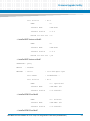
Overview . . . . . . . . . . . . . . . . . . . . . . . . . . . . . . . . . . . . . . . . . . . . . . . . . . . . . . . . . . . . . . . . . . . . . . . . . . 57
Firmware Recovery Image Files . . . . . . . . . . . . . . . . . . . . . . . . . . . . . . . . . . . . . . . . . . . . . . . . . . . . . . . 57
Backup Concept . . . . . . . . . . . . . . . . . . . . . . . . . . . . . . . . . . . . . . . . . . . . . . . . . . . . . . . . . . . . . . . . . . . . 58
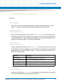
fcu—Firmware Upgrade Command-Line Utility . . . . . . . . . . . . . . . . . . . . . . . . . . . . . . . . . . . . . . . . . 62
Upgrading a Firmware Image . . . . . . . . . . . . . . . . . . . . . . . . . . . . . . . . . . . . . . . . . . . . . . . . . . . . . . . . 66
4.5.1 BIOS Upgrade. . . . . . . . . . . . . . . . . . . . . . . . . . . . . . . . . . . . . . . . . . . . . . . . . . . . . . . . . . . . . . . . 67
4.5.2 IPMC Upgrade . . . . . . . . . . . . . . . . . . . . . . . . . . . . . . . . . . . . . . . . . . . . . . . . . . . . . . . . . . . . . . . 68
4.5.3 FPGA Upgrade . . . . . . . . . . . . . . . . . . . . . . . . . . . . . . . . . . . . . . . . . . . . . . . . . . . . . . . . . . . . . . . 69
Hardware Platform Management . . . . . . . . . . . . . . . . . . . . . . . . . . . . . . . . . . . . . . . . . . . . . . . . . . . . . . 71
5.1
5.2
5.3
5.4
5.5
4
Linux Services Initialization . . . . . . . . . . . . . . . . . . . . . . . . . . . . . . . . . . . . . . . . . . . . . . . . . . . . . . . . . . 46
3.5.1 RC Scripts . . . . . . . . . . . . . . . . . . . . . . . . . . . . . . . . . . . . . . . . . . . . . . . . . . . . . . . . . . . . . . . . . . . 47
Network Services Configuration . . . . . . . . . . . . . . . . . . . . . . . . . . . . . . . . . . . . . . . . . . . . . . . . . . . . . . 47
3.6.1 ATCA-7360/7365 Ethernet Interfaces. . . . . . . . . . . . . . . . . . . . . . . . . . . . . . . . . . . . . . . . . . . 47
3.6.2 IXGBE 10GB/s Network Driver . . . . . . . . . . . . . . . . . . . . . . . . . . . . . . . . . . . . . . . . . . . . . . . . . 49
Tools . . . . . . . . . . . . . . . . . . . . . . . . . . . . . . . . . . . . . . . . . . . . . . . . . . . . . . . . . . . . . . . . . . . . . . . . . . . . . . 49
3.7.1 Performance Tool . . . . . . . . . . . . . . . . . . . . . . . . . . . . . . . . . . . . . . . . . . . . . . . . . . . . . . . . . . . . 50
3.7.2 IPMIBPAR . . . . . . . . . . . . . . . . . . . . . . . . . . . . . . . . . . . . . . . . . . . . . . . . . . . . . . . . . . . . . . . . . . . 51
3.7.3 CoreTemp. . . . . . . . . . . . . . . . . . . . . . . . . . . . . . . . . . . . . . . . . . . . . . . . . . . . . . . . . . . . . . . . . . . 53
VGA Support . . . . . . . . . . . . . . . . . . . . . . . . . . . . . . . . . . . . . . . . . . . . . . . . . . . . . . . . . . . . . . . . . . . . . . . 53
3.8.1 Software Support . . . . . . . . . . . . . . . . . . . . . . . . . . . . . . . . . . . . . . . . . . . . . . . . . . . . . . . . . . . . 53
3.8.2 Configuration of the Framebuffer Driver . . . . . . . . . . . . . . . . . . . . . . . . . . . . . . . . . . . . . . . . 54
Network Performance . . . . . . . . . . . . . . . . . . . . . . . . . . . . . . . . . . . . . . . . . . . . . . . . . . . . . . . . . . . . . . 55
Overview . . . . . . . . . . . . . . . . . . . . . . . . . . . . . . . . . . . . . . . . . . . . . . . . . . . . . . . . . . . . . . . . . . . . . . . . . . 71
hpmagentd—HPM Agent Daemon . . . . . . . . . . . . . . . . . . . . . . . . . . . . . . . . . . . . . . . . . . . . . . . . . . . . 72
hpm—Start-Up Script . . . . . . . . . . . . . . . . . . . . . . . . . . . . . . . . . . . . . . . . . . . . . . . . . . . . . . . . . . . . . . . 74
hpm—Shutdown and Reboot Scripts . . . . . . . . . . . . . . . . . . . . . . . . . . . . . . . . . . . . . . . . . . . . . . . . . . 75
hpmcmd—HPM Command Utility . . . . . . . . . . . . . . . . . . . . . . . . . . . . . . . . . . . . . . . . . . . . . . . . . . . . 76
5.5.1 Command Overview. . . . . . . . . . . . . . . . . . . . . . . . . . . . . . . . . . . . . . . . . . . . . . . . . . . . . . . . . . 77
5.5.2 Supported Commands. . . . . . . . . . . . . . . . . . . . . . . . . . . . . . . . . . . . . . . . . . . . . . . . . . . . . . . . 79
5.5.2.1 bye . . . . . . . . . . . . . . . . . . . . . . . . . . . . . . . . . . . . . . . . . . . . . . . . . . . . . . . . . . . . . . . . 79
5.5.2.2 bootbankget . . . . . . . . . . . . . . . . . . . . . . . . . . . . . . . . . . . . . . . . . . . . . . . . . . . . . . . 80
Basic Blade Services Software on ATCA-7360/7365 Programmer’s Reference (6806800K42E)
Contents
5.5.2.3
5.5.2.4
5.5.2.5
5.5.2.6
5.5.2.7
5.5.2.8
5.5.2.9
5.5.2.10
5.5.2.11
5.5.2.12
5.5.2.13
5.5.2.14
5.5.2.15
5.5.2.16
5.5.2.17
5.5.2.18
5.5.2.19
5.5.2.20
5.5.2.21
5.5.2.22
5.5.2.23
5.5.2.24
5.5.2.25
5.5.2.26
5.5.2.27
5.5.2.28
5.5.2.29
5.5.2.30
5.5.2.31
5.5.2.32
5.5.2.33
5.5.2.34
5.5.2.35
5.5.2.36
5.5.2.37
5.5.2.38
bootbankset . . . . . . . . . . . . . . . . . . . . . . . . . . . . . . . . . . . . . . . . . . . . . . . . . . . . . . . 80
bootparamerase . . . . . . . . . . . . . . . . . . . . . . . . . . . . . . . . . . . . . . . . . . . . . . . . . . . . 81
bootparamget . . . . . . . . . . . . . . . . . . . . . . . . . . . . . . . . . . . . . . . . . . . . . . . . . . . . . . 82
bootparamset . . . . . . . . . . . . . . . . . . . . . . . . . . . . . . . . . . . . . . . . . . . . . . . . . . . . . . 83
chinfo . . . . . . . . . . . . . . . . . . . . . . . . . . . . . . . . . . . . . . . . . . . . . . . . . . . . . . . . . . . . . 84
cmd . . . . . . . . . . . . . . . . . . . . . . . . . . . . . . . . . . . . . . . . . . . . . . . . . . . . . . . . . . . . . . . 85
deviceid . . . . . . . . . . . . . . . . . . . . . . . . . . . . . . . . . . . . . . . . . . . . . . . . . . . . . . . . . . . 86
exit . . . . . . . . . . . . . . . . . . . . . . . . . . . . . . . . . . . . . . . . . . . . . . . . . . . . . . . . . . . . . . . . 87
frudata . . . . . . . . . . . . . . . . . . . . . . . . . . . . . . . . . . . . . . . . . . . . . . . . . . . . . . . . . . . . 87
fruinfoget . . . . . . . . . . . . . . . . . . . . . . . . . . . . . . . . . . . . . . . . . . . . . . . . . . . . . . . . . . 88
fruinv . . . . . . . . . . . . . . . . . . . . . . . . . . . . . . . . . . . . . . . . . . . . . . . . . . . . . . . . . . . . . . 89
fruread . . . . . . . . . . . . . . . . . . . . . . . . . . . . . . . . . . . . . . . . . . . . . . . . . . . . . . . . . . . . 89
fruwrite . . . . . . . . . . . . . . . . . . . . . . . . . . . . . . . . . . . . . . . . . . . . . . . . . . . . . . . . . . . . 90
help . . . . . . . . . . . . . . . . . . . . . . . . . . . . . . . . . . . . . . . . . . . . . . . . . . . . . . . . . . . . . . . 91
ipmbaddress . . . . . . . . . . . . . . . . . . . . . . . . . . . . . . . . . . . . . . . . . . . . . . . . . . . . . . . 91
ipmcdevice . . . . . . . . . . . . . . . . . . . . . . . . . . . . . . . . . . . . . . . . . . . . . . . . . . . . . . . . 91
ipmcstatus . . . . . . . . . . . . . . . . . . . . . . . . . . . . . . . . . . . . . . . . . . . . . . . . . . . . . . . . . 91
ledget . . . . . . . . . . . . . . . . . . . . . . . . . . . . . . . . . . . . . . . . . . . . . . . . . . . . . . . . . . . . . 92
ledprop . . . . . . . . . . . . . . . . . . . . . . . . . . . . . . . . . . . . . . . . . . . . . . . . . . . . . . . . . . . . 92
ledset . . . . . . . . . . . . . . . . . . . . . . . . . . . . . . . . . . . . . . . . . . . . . . . . . . . . . . . . . . . . . 93
loglevelget . . . . . . . . . . . . . . . . . . . . . . . . . . . . . . . . . . . . . . . . . . . . . . . . . . . . . . . . . 95
loglevelset . . . . . . . . . . . . . . . . . . . . . . . . . . . . . . . . . . . . . . . . . . . . . . . . . . . . . . . . . 95
macaddress . . . . . . . . . . . . . . . . . . . . . . . . . . . . . . . . . . . . . . . . . . . . . . . . . . . . . . . . 96
motshelftype . . . . . . . . . . . . . . . . . . . . . . . . . . . . . . . . . . . . . . . . . . . . . . . . . . . . . . . 96
partnumber . . . . . . . . . . . . . . . . . . . . . . . . . . . . . . . . . . . . . . . . . . . . . . . . . . . . . . . . 97
physlotnumber . . . . . . . . . . . . . . . . . . . . . . . . . . . . . . . . . . . . . . . . . . . . . . . . . . . . . 97
portget . . . . . . . . . . . . . . . . . . . . . . . . . . . . . . . . . . . . . . . . . . . . . . . . . . . . . . . . . . . . 97
portset . . . . . . . . . . . . . . . . . . . . . . . . . . . . . . . . . . . . . . . . . . . . . . . . . . . . . . . . . . . . 98
quit . . . . . . . . . . . . . . . . . . . . . . . . . . . . . . . . . . . . . . . . . . . . . . . . . . . . . . . . . . . . . . 100
rebootpath . . . . . . . . . . . . . . . . . . . . . . . . . . . . . . . . . . . . . . . . . . . . . . . . . . . . . . . . 100
sdr . . . . . . . . . . . . . . . . . . . . . . . . . . . . . . . . . . . . . . . . . . . . . . . . . . . . . . . . . . . . . . . 101
sdr_dump . . . . . . . . . . . . . . . . . . . . . . . . . . . . . . . . . . . . . . . . . . . . . . . . . . . . . . . . . 101
sendcmd . . . . . . . . . . . . . . . . . . . . . . . . . . . . . . . . . . . . . . . . . . . . . . . . . . . . . . . . . . 102
sdrinfo . . . . . . . . . . . . . . . . . . . . . . . . . . . . . . . . . . . . . . . . . . . . . . . . . . . . . . . . . . . . 103
shelfaddress . . . . . . . . . . . . . . . . . . . . . . . . . . . . . . . . . . . . . . . . . . . . . . . . . . . . . . . 103
shelfslots . . . . . . . . . . . . . . . . . . . . . . . . . . . . . . . . . . . . . . . . . . . . . . . . . . . . . . . . . 103
Basic Blade Services Software on ATCA-7360/7365 Programmer’s Reference (6806800K42E)
5
Contents
Contents
5.5.2.39
5.5.2.40
5.5.2.41
5.5.2.42
5.5.2.43
5.5.2.44
5.5.2.45
5.5.2.46
6
HPI-B Software . . . . . . . . . . . . . . . . . . . . . . . . . . . . . . . . . . . . . . . . . . . . . . . . . . . . . . . . . . . . . . . . . . . . . 111
6.1
7
Building Kernel and Root File System . . . . . . . . . . . . . . . . . . . . . . . . . . . . . . . . . . . . . . . . . . . . . . . . . 117
8.1.1 Prerequisites . . . . . . . . . . . . . . . . . . . . . . . . . . . . . . . . . . . . . . . . . . . . . . . . . . . . . . . . . . . . . . . 117
8.1.2 Additional Kernel Patches . . . . . . . . . . . . . . . . . . . . . . . . . . . . . . . . . . . . . . . . . . . . . . . . . . . . 119
8.1.3 Project Setup . . . . . . . . . . . . . . . . . . . . . . . . . . . . . . . . . . . . . . . . . . . . . . . . . . . . . . . . . . . . . . . 119
8.1.3.1 Project Configure Script . . . . . . . . . . . . . . . . . . . . . . . . . . . . . . . . . . . . . . . . . . . . 120
8.1.3.2 Using Wind River Work Bench for PNE3.0 . . . . . . . . . . . . . . . . . . . . . . . . . . . . . 122
8.1.4 Kernel Configuration . . . . . . . . . . . . . . . . . . . . . . . . . . . . . . . . . . . . . . . . . . . . . . . . . . . . . . . . 124
8.1.5 Root File System Configuration . . . . . . . . . . . . . . . . . . . . . . . . . . . . . . . . . . . . . . . . . . . . . . . 124
8.1.6 Getting Root File System and RAMDISK Image . . . . . . . . . . . . . . . . . . . . . . . . . . . . . . . . . . 124
Installing and Configuring BBS . . . . . . . . . . . . . . . . . . . . . . . . . . . . . . . . . . . . . . . . . . . . . . . . . . . . . . . . 127
A.1
6
Overview . . . . . . . . . . . . . . . . . . . . . . . . . . . . . . . . . . . . . . . . . . . . . . . . . . . . . . . . . . . . . . . . . . . . . . . . . 113
Board Control Tool . . . . . . . . . . . . . . . . . . . . . . . . . . . . . . . . . . . . . . . . . . . . . . . . . . . . . . . . . . . . . . . . 115
7.2.1 LEDCTRL . . . . . . . . . . . . . . . . . . . . . . . . . . . . . . . . . . . . . . . . . . . . . . . . . . . . . . . . . . . . . . . . . . . 115
7.2.2 FPGA_TEST . . . . . . . . . . . . . . . . . . . . . . . . . . . . . . . . . . . . . . . . . . . . . . . . . . . . . . . . . . . . . . . . . 115
Kernel and Root File System Config using PNE 3.0 . . . . . . . . . . . . . . . . . . . . . . . . . . . . . . . . . . . . . . . 117
8.1
A
Overview . . . . . . . . . . . . . . . . . . . . . . . . . . . . . . . . . . . . . . . . . . . . . . . . . . . . . . . . . . . . . . . . . . . . . . . . . 111
Board Control Module . . . . . . . . . . . . . . . . . . . . . . . . . . . . . . . . . . . . . . . . . . . . . . . . . . . . . . . . . . . . . . . 113
7.1
7.2
8
shutdownpath . . . . . . . . . . . . . . . . . . . . . . . . . . . . . . . . . . . . . . . . . . . . . . . . . . . . . 104
slotmap . . . . . . . . . . . . . . . . . . . . . . . . . . . . . . . . . . . . . . . . . . . . . . . . . . . . . . . . . . 104
slotnumber . . . . . . . . . . . . . . . . . . . . . . . . . . . . . . . . . . . . . . . . . . . . . . . . . . . . . . . 105
solcfgget . . . . . . . . . . . . . . . . . . . . . . . . . . . . . . . . . . . . . . . . . . . . . . . . . . . . . . . . . 105
solcfgset . . . . . . . . . . . . . . . . . . . . . . . . . . . . . . . . . . . . . . . . . . . . . . . . . . . . . . . . . . 106
upgrade . . . . . . . . . . . . . . . . . . . . . . . . . . . . . . . . . . . . . . . . . . . . . . . . . . . . . . . . . . 107
version . . . . . . . . . . . . . . . . . . . . . . . . . . . . . . . . . . . . . . . . . . . . . . . . . . . . . . . . . . . 107
watchdog . . . . . . . . . . . . . . . . . . . . . . . . . . . . . . . . . . . . . . . . . . . . . . . . . . . . . . . . . 108
Installing BBS Using Hard Disk . . . . . . . . . . . . . . . . . . . . . . . . . . . . . . . . . . . . . . . . . . . . . . . . . . . . . . . 127
Basic Blade Services Software on ATCA-7360/7365 Programmer’s Reference (6806800K42E)
Contents
B
Related Documentation . . . . . . . . . . . . . . . . . . . . . . . . . . . . . . . . . . . . . . . . . . . . . . . . . . . . . . . . . . . . . . 135
B.1
B.2
B.3
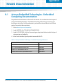
Artesyn Embedded Technologies - Embedded Computing Documentation . . . . . . . . . . . . . . . 135
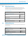
Related Specifications . . . . . . . . . . . . . . . . . . . . . . . . . . . . . . . . . . . . . . . . . . . . . . . . . . . . . . . . . . . . . . 136
Additional Resources . . . . . . . . . . . . . . . . . . . . . . . . . . . . . . . . . . . . . . . . . . . . . . . . . . . . . . . . . . . . . . 136
Basic Blade Services Software on ATCA-7360/7365 Programmer’s Reference (6806800K42E)
7
Contents
Contents
8
Basic Blade Services Software on ATCA-7360/7365 Programmer’s Reference (6806800K42E)
List of Tables
Table 2-1
Table 2-2
Table 2-3
Table 3-1
Table 3-2
Table 3-3
Table 3-4
Table 3-5
Table 5-1
Table 8-1
Table B-1
Table B-2
Table B-3
BBS Installation/Boot Options - Main Set-Up and Configuration Steps . . . . . . . . . . . . . . . . . 23
Installation Scripts . . . . . . . . . . . . . . . . . . . . . . . . . . . . . . . . . . . . . . . . . . . . . . . . . . . . . . . . . . . . . 24
BBS Distribution Packages . . . . . . . . . . . . . . . . . . . . . . . . . . . . . . . . . . . . . . . . . . . . . . . . . . . . . . . 25
Long POST Standard Test Routines - Generated IPMI Data . . . . . . . . . . . . . . . . . . . . . . . . . . . 44
Long POST Default Test Routines . . . . . . . . . . . . . . . . . . . . . . . . . . . . . . . . . . . . . . . . . . . . . . . . . 45
Long POST Script LPmain.sh - Options . . . . . . . . . . . . . . . . . . . . . . . . . . . . . . . . . . . . . . . . . . . . 46
Generic Linux Run Levels . . . . . . . . . . . . . . . . . . . . . . . . . . . . . . . . . . . . . . . . . . . . . . . . . . . . . . . . 46
VGA driver supporting modes . . . . . . . . . . . . . . . . . . . . . . . . . . . . . . . . . . . . . . . . . . . . . . . . . . . 54
Command Overview . . . . . . . . . . . . . . . . . . . . . . . . . . . . . . . . . . . . . . . . . . . . . . . . . . . . . . . . . . . 77
ATCA-7360/7365 specific kernel patches . . . . . . . . . . . . . . . . . . . . . . . . . . . . . . . . . . . . . . . . . 119
Artesyn Embedded Technologies - Embedded Computing Publications . . . . . . . . . . . . . . 135
Related Specifications . . . . . . . . . . . . . . . . . . . . . . . . . . . . . . . . . . . . . . . . . . . . . . . . . . . . . . . . . 136
Additional Resources . . . . . . . . . . . . . . . . . . . . . . . . . . . . . . . . . . . . . . . . . . . . . . . . . . . . . . . . . . 136
Basic Blade Services Software on ATCA-7360/7365 Programmer’s Reference (6806800K42E)
9
List of Tables
10
Basic Blade Services Software on ATCA-7360/7365 Programmer’s Reference (6806800K42E)
List of Figures
Figure 1-1
Figure 5-1
BBS Architecture . . . . . . . . . . . . . . . . . . . . . . . . . . . . . . . . . . . . . . . . . . . . . . . . . . . . . . . . 20
Software Levels of the HPM Architecture . . . . . . . . . . . . . . . . . . . . . . . . . . . . . . . . . . . 72
Basic Blade Services Software on ATCA-7360/7365 Programmer’s Reference (6806800K42E)
11
List of Figures
12
Basic Blade Services Software on ATCA-7360/7365 Programmer’s Reference (6806800K42E)
About this Manual
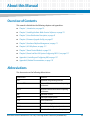
Overview of Contents
This manual is divided into the following chapters and appendices.
Chapter 1, Introduction, on page 19
Chapter 2, Installing the Basic Blade Services Software, on page 23
Chapter 3, Linux Distribution Description, on page 43
Chapter 4, Firmware Upgrade Facility, on page 57
Chapter 5, Hardware Platform Management, on page 71
Chapter 6, HPI-B Software, on page 111
Chapter 7, Board Control Module, on page 113
Chapter 8, Kernel and Root File System Config using PNE 3.0, on page 117
Appendix A, Installing and Configuring BBS, on page 127
Appendix B, Related Documentation, on page 135
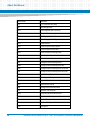
Abbreviations
This document uses the following abbreviations:
Abbreviation
Definition
API
Application Programming Interface
AdvancedTCA
Advanced Telecommunications Computing
Architecture
ATCA
Advanced Telecommunications Computing
Architecture
BBS
Basic Blade Services
BIOS
Basic Input Output System
CGL
Carrier Grade Linux
CPU
Central Processing Unit
DHCP
Dynamic Host Configuration Protocol
ECC
Embedded Communications Computing
Basic Blade Services Software on ATCA-7360/7365 Programmer’s Reference (6806800K42E)
13
About this Manual
14
About this Manual
Abbreviation
Definition
FCU
FUF Command Line Utility
FM
Fault Management
FPGA
Field Programmable Gate Array
FRI
Firmware Recovery Image
FRU
Field Replaceable Unit
FUF
Firmware Upgrade Facility
FWH
Firmware Hub
GPIO
General Purpose Input/Output
HPI
Hardware Platform Interface
HPM
Hardware Platform Management
I/O
Input Output
IP
Internet Protocol
IPM
Intelligent Platform Management
IPMB
Intelligent Platform Management Bus
IPMC
Intelligent Platform Management Controller
IPMI
Intelligent Platform Management Interface
LED
Light Emitting Diode
LSP
Linux Support Package
LUN
Logic Unit Number
MAC
Media Access Control
MIB
Management Information Base
NTP
Network Time Protocol
OEM
Original Equipment Manufacturer
OSDL
Open Source Development Labs
PC
Personal Computer
PCI
Peripheral Component Interconnect
PCIx
PCI Express
Basic Blade Services Software on ATCA-7360/7365 Programmer’s Reference (6806800K42E)
About this Manual
Abbreviation
Definition
PICMG
PCI Industrial Computers Manufacturers
Group
PXE
Preboot Execution Environment
RAM
Random Access Memory
ROM
Read Only Memory
RPM
RedHat Package Manager
RTM
Rear Transition Module
SAF
Service Availability Forum
SAS
Serial Attached SCSI
SATA
Serial ATA
SCSI
Small Computer System Interface
SDR
Sensor Data Record
SMI
Serial Management Interface
SNMP
Simple Network Management Protocol
SSD
Solid State Disk
SSH
Secure Shell
SSU
Synchronization Supply Unit
TAR
Tape Archive
TCP
Transmission Control Protocol
TFTP
Trivial File Transfer Protocol
UDP
User Datagram Protocol
USB
Universal Serial Bus
VGA
Video Graphics Array
Basic Blade Services Software on ATCA-7360/7365 Programmer’s Reference (6806800K42E)
15
About this Manual
About this Manual
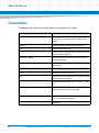
Conventions
The following table describes the conventions used throughout this manual.
Notation
Description
0x00000000
Typical notation for hexadecimal numbers (digits are
0 through F), for example used for addresses and
offsets
0b0000
Same for binary numbers (digits are 0 and 1)
bold
Used to emphasize a word
Screen
Used for on-screen output and code related elements
or commands in body text
Courier + Bold
Used to characterize user input and to separate it
from system output
Reference
Used for references and for table and figure
descriptions
File > Exit
Notation for selecting a submenu
<text>
Notation for variables and keys
[text]
Notation for software buttons to click on the screen
and parameter description
...
Repeated item for example node 1, node 2, ..., node
12
.
Omission of information from example/command
that is not necessary at the time being
.
.
16
..
Ranges, for example: 0..4 means one of the integers
0,1,2,3, and 4 (used in registers)
|
Logical OR
Basic Blade Services Software on ATCA-7360/7365 Programmer’s Reference (6806800K42E)
About this Manual
Notation
Description
Indicates a hazardous situation which, if not avoided,
could result in death or serious injury
Indicates a hazardous situation which, if not avoided,
may result in minor or moderate injury
Indicates a property damage message
No danger encountered. Pay attention to important
information
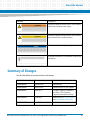
Summary of Changes
See the table below for manual revisions and changes.
Part Number
Date
Description
6806800K42A
January 2010
Initial release.
6806800K42B
March 2010
Updated for ATCA-7365 support.
6806800K42C
April 2010
Compare support is removed in
section 4.4, "fcu–Firmware
Upgrade Command-Line Utility"
6806800K42D
June 2010
Added sections 3.8, VGA Support
and 3.9, Network Performance.
6806800K42E
June 2014
Re-branded to Artesyn.
Basic Blade Services Software on ATCA-7360/7365 Programmer’s Reference (6806800K42E)
17
About this Manual
18
About this Manual
Basic Blade Services Software on ATCA-7360/7365 Programmer’s Reference (6806800K42E)
Chapter 1
Introduction
1.1
Overview
This manual is applicable to part number; SA-BBS-WR-7360-F.
The Basic Blades Services (BBS) software provides a set of services that support the blade on
which the software is installed. BBS includes:
1.2
Several custom hardware management functions for the unique hardware of the blade.
A set of management routines for Linux and all hardware interfaces. Management access
includes support for SNMP and a local console interface based on a standard Linux
command shell.
HPI-B
This release contains an RPM which contains all files necessary for developing HPI-B
applications. For further information refer to the System Management Interface Based on
HPI-B (Centellis CO 31kX/4100/2000/4410) User’s Guide.
The ATCA-7360 differs from the ATCA-7365 only in terms of the used Intel CPU. The
functionality of the Software of both versions ATCA-7360 and ATCA-7365 remains the
same. Also IPMI Firmware and BIOS for both blade types are covered in the ATCA-7365
packages. However there will be no ARTM ATCA-7365 therefore these packages will not be
changed.
Software Building Blocks
BBS services include a common set of functionality which is available for all AdvancedTCA
blades and a unique set of functionality which is tailored to a particular blade.
Basic Blade Services Software on ATCA-7360/7365 Programmer’s Reference (6806800K42E)
19
Introduction
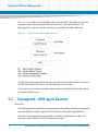
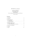
Figure 1-1 depicts the architecture of the BBS software.
Figure 1-1
BBS Architecture
BBS for the ATCA-7360/7365 consists of the following main software and services:
20
Firmware Upgrade Facility
The Firmware Upgrade Facility (FUF) provides a uniform way to upgrade firmware on
Artesyn blades, regardless on which flash locations the firmware is stored. FUF upgrades
the BIOS firmware as well as the IPMC firmware (via HPM agent). The FUF currently consists
of a Firmware Upgrade Command Line Utility (FCU), flash device drivers, and specially
prepared firmware recovery image files. The FUF can be used on switch and node blades.
Linux Operating System
Wind River Enterprise Linux 3.0 (Carrier Grade Linux) is the operating system for BBS blades
and modules. The operating system comes with kernel 2.6.27. Various Linux services
(above the kernel) will be activated by the BBS installation scripts.
Hardware Platform Management
Hardware Platform Management (HPM) in AdvancedTCA systems is based on Intelligent
Platform Management Interface specification (IPMI). IPMI commands can be complex and
cumbersome. Using a certain set of commands, HPM facilitates the blade or module-level
hardware management.
Basic Blade Services Software on ATCA-7360/7365 Programmer’s Reference (6806800K42E)
Introduction
SNMP Agent
As each BBS blade is individually managed, the default installation script installs and
initializes the "Net-SNMP" agent.
HPI-B
This release contains an RPM which contains all files necessary for developing HPI-B
applications. For further information refer to the System Management Interface Based on
HPI-B (Centellis CO 31kX/4100/2000/4410) User’s Guide.
Basic Blade Services Software on ATCA-7360/7365 Programmer’s Reference (6806800K42E)
21
Introduction
22
Basic Blade Services Software on ATCA-7360/7365 Programmer’s Reference (6806800K42E)
Chapter 2
Installing the Basic Blade Services Software
2.1
Overview
Artesyn provides software images, including software updates, to its licensed customers. In
order to obtain the latest BBS software versions, contact your local sales representative.
Generally, there are three typical ways of installing/booting the BBS software on ATCA7360/7365:
Diskless client boot via network
Installation and booting from SATA/SAS hard disk
Installation and booting from on-board USB disk
On ATCA-7360/7365 the SATA-HDD or SAS-HDD can reside on the RTM. As an option a Solid
State Disk (SSD) with SATA interface (SATA cube) can be placed on the front board.
For all these options you need to set up an external TFTP server to retrieve the required BBS
files. Furthermore you need to do some initial configurations. Table 2-1 provides an overview
of the main steps you need to take for the three installation/boot options. The detailed
procedures can be found in the following sections.
Table 2-1 BBS Installation/Boot Options - Main Set-Up and Configuration Steps
Installation/Boot Option
Main Set-Up and Configuration Steps
Diskless client boot. Refer
Configuring ATCA-7360/7365 for
Diskless Client Boot of the BBS
Software on page 32.
1.
Set up and configure external TFTP boot server
2.
Configure DHCP server
3.
Configure PXE boot options
4.
Configure ATCA-7360/7365 BIOS to boot from network
Installation and booting from
SATA/SAS hard disk. The hard
disk can be located on the RTM
or locally (as SATA cube) on the
front board. Refer Installing BBS
Software on Hard Disk Drive on
page 33.
1.
Set up and configure external TFTP boot server
2.
Configure DHCP server
3.
Configure PXE boot options
4.
Configure ATCA-7360/7365 BIOS for network boot
5.
Boot BBS initrd image
6.
Install BBS image on hard disk (via install script)
7.
Configure ATCA-7360/7365 BIOS to boot from hard disk
Basic Blade Services Software on ATCA-7360/7365 Programmer’s Reference (6806800K42E)
23
Installing the Basic Blade Services Software
Table 2-1 BBS Installation/Boot Options - Main Set-Up and Configuration Steps (continued)
Installation/Boot Option
Main Set-Up and Configuration Steps
Installation and booting from
on-board USB flash. Refer
Installing BBS Software on OnBoard USB Disk on page 37.
1.
Set up and configure external TFTP boot server
2.
Configure DHCP server
3.
Configure PXE boot options
4.
Configure ATCA-7360/7365 BIOS for network boot
5.
Boot BBS initrd image
6.
Install BBS image on USB flash (via install script)
7.
Configure ATCA-7360/7365 BIOS to boot from USB flash
For more information about the rpm command, see its man page.
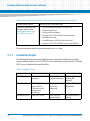
2.1.1
Installation Scripts
The following table describes the installation scripts required for installing the operating
system and blade utilities for ATCA-7360/7365. These installation scripts require a TFTP and a
DHCP server to download the installation files.
Table 2-2 Installation Scripts
24
linuxrc
flashrfsrc
flashrc
Installed packages
Kernel, RFS and additional
packages
Kernel, RFS and
additional packages
Kernel, Ramdisk
(including BBS
packages)
Features
Enhanced partition
layout, SMART-/
Timezone and NTP
configuration,
Autoconfig
Simple partition
layout and
autoconfig
Timezone-/NTP
configuration
Suitable for devices
HDD, SSD > 30 GB
HDD, SSD or onboard USB flash
On-board USB flash or
USB stick
Basic Blade Services Software on ATCA-7360/7365 Programmer’s Reference (6806800K42E)
Installing the Basic Blade Services Software
2.1.2
Package Information
BBS software is packaged with the Red Hat Package Manager (RPM) and is installed as part of
the standard installation. In general, you will not need to install or upgrade an individual
package.
The BBS distribution contains the following packages.
Table 2-3 BBS Distribution Packages
Description
File Name
Operating System Kernel (Kernel
version 2.6.27)
kernel
Ramdisk image for netboot
ramdisk.image.gz
Hard Disk Installation
Root file system for hard disk
installation
rootfs.tar.gz
RamFS in order to support UUID
parameters for disk boot.
initrd0.img
Kernel command line
default.bbs-atca7365
Check sum of all files and RPMs
files.sha1sum
BIOS package
bbs-cpu-atca7365-<version>.rpm
IPMI firmware package (front
blade)
bbs-ipmc-atca7365-<version>.rpm
IPMI booter package (front blade)
bbs-ipmc-boot-atca7365-<version>.rpm
IPMI firmware package (RTM)
bbs-artm-atca7360-<version>.rpm
IPMI firmware booter package
(RTM)
bbs-artm-boot-atca7360-<version>.rpm
FPGA firmware package
bbs-fpga-atca7365-<version>.rpm
Firmware Upgrade functionality Upgrade tool for BIOS, FPGA and
IPMC on front blade and RTM
bbs-fuf-atca7365-<version>-pne30.rpm
Hardware Platform Management
consisting of daemon and client
bbs-hpmagentcmd-atca7365-<version>-pne30.rpm
Flash driver for SFMEM module
bbs-sfmem-atca7365-<version>-pne30.rpm
Basic Blade Services Software on ATCA-7360/7365 Programmer’s Reference (6806800K42E)
25
Installing the Basic Blade Services Software
Table 2-3 BBS Distribution Packages (continued)
Description
File Name
Persistent RAM driver
bbs-pram-atca7365-<version>-pne30.rpm
Board control utility to get FPGA
data
bbs-boardctrl-atca7365-<version>-pne30.rpm
HPI-B package
bbs-hpib-<version>-wrspne3.0-linux.rpm
HPI-B client package
bbs-hpib-clientsrc-<version>-wrspne3.0-linux.rpm
HPI-B developer package
bbs-hpib-devel-<version>-wrspne3.0-linux.rpm
Flashrom package (update tool for
BIOS flash via SPI interface)
bbs-flashrom-atca7360-<version>-pne30.rpm
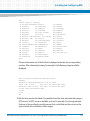
The following rpm commands are useful to review package information.
2.1.3
Command
Description
rpm -qa
List all installed packages. Use rpm -qa | grep hpi to list only
HPI packages.
rpm -ql <package-name>
List the content of a package, where package-name is the name
of a specific package, for example, rpm -ql openhpi.
rpm -qi <package-name>
List information about a package, where package-name is the
name of a specific package, for example, rpm -qi openhpi.
rpm -qf <path to file>
Finds out which RPM a file belongs to.
Accessing the ATCA-7360/7365 via Serial Console
In most procedures described in the following sections you need to invoke Linux commands or
configure BIOS settings. In order to do this, you need to access the ATCA-7360/7365 via the
face plate serial port. If using a serial console or terminal emulator, the default serial port
settings are:
26
9600 baud
No parity
Eight data bits
One stop bit
Basic Blade Services Software on ATCA-7360/7365 Programmer’s Reference (6806800K42E)
Installing the Basic Blade Services Software
Flow control: xon/xoff
Emulated terminal type: VT100
If you wish to access Linux via a Linux shell, the default account login is root with the password
root. Refer Login on page 43, for more information.
2.2
Configuring TFTP, DHCP and PXE
For all installation and boot options, you need to set up and configure a TFTP server.
Furthermore, for the diskless client and hard disk installation/boot option, you need to
configure the system’s DHCP server and configure PXE boot options. All related steps are
described in the following section.
2.2.1
Create /tftpboot Directory and Copy Target Files
It is customary to place TFTP files in a tftpboot directory. Regardless of the file system node
you specify as the root for your TFTP service, the installation scripts expect a certain directory
structure when retrieving files.
Creating the /tftpboot Directory and Copying the Target Files
To create the expected directory structure and copy the needed files, follow these steps.
1. On the host create a /tftpboot directory, if it does not already exist
mkdir /tftpboot
2. Create a subdirectory for ATCA-7360/7365, for example:
mkdir /tftpboot/atca-7365
3. Depending on the boot/installation option, copy or move the required installation
files to the subdirectory. Refer Table 2-3 on page 25 for BBS distribution packaging.
The exact file names in your BBS release may be different. Refer the release notes applicable
to your particular release. Table 2-3 on page 25 is only an example of a possible packaging
with example file names.
Please ensure that the file attributes are set to 755, so that PXE can access and load the files.
Basic Blade Services Software on ATCA-7360/7365 Programmer’s Reference (6806800K42E)
27
Installing the Basic Blade Services Software
To ensure that the downloaded files are correct, sha1 checksums are used. If the
sha1 checksums are not correct, an error message is displayed during the installation process.
If you make changes to any of the files, you need to remember to update the sha1 checksum
file as well. If you still get an error message during the installation, it is likely that one or more
of the files have not been copied successfully. Copy all the files to the tftpboot directory
again and restart the installation.
2.2.2
Configuring a TFTP Server
The instructions in this section can be used to configure standard TFTP servers (BSD
compatible) that are under the control of xinetd. The exact configuration settings depend on
the particular system configuration, the following instructions are only meant as a general
guideline.
Configuring a TFTP Server
To configure TFTP as root on the host, complete the following steps:
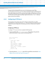
1. Create (or edit) the file /etc/inetd.d/tftp. Depending on the particular
system environment, it may contain the following entries.
#/etc/inetd.d/tftp
service tftp
{
socket_type = dgram
wait = yes
user = root
log_on_success += USERID
log_on_failure += USERID
server = /bin/in.tftpd
server_args = -r blksize /tftpboot
disable = no
protocol = udp
}
2. Create the directory /tftpboot and add the needed files as described in Create
/tftpboot Directory and Copy Target Files on page 27.
28
Basic Blade Services Software on ATCA-7360/7365 Programmer’s Reference (6806800K42E)
Installing the Basic Blade Services Software
3. If there are any TFTP daemons that have not timed out, you need to stop them.
Enter the following command to do so:
killall in.tftpd
4. Enter the following command to have inetd re-read its configuration file:
/etc/rc.d/init.d/inetd restart
Your TFTP server is now configured.
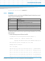
2.2.3
Configuring DHCP
The DHCP configuration file on an TFTP server (for example ATCA-F120 or an external TFTP
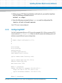
server) resides in /etc/dhcpd.conf. Make sure this file contains the following entries (IP
addresses may be different in your configuration):
#
# Sample dhcpd configuration file
#
#
allow bootp;
allow booting;
authoritative;
filename "pxelinux.0";
ddns-update-style ad-hoc;
option domain-name "booting.com";
option subnet-mask 255.255.255.0;
default-lease-time 600;
max-lease-time 7200;
#Base 1 interfaces
subnet 192.168.21.0 netmask 255.255.255.0 {
range 192.168.21.100 192.168.21.125;
option broadcast-address 192.168.21.255;
}
#Base 2 interfaces
Basic Blade Services Software on ATCA-7360/7365 Programmer’s Reference (6806800K42E)
29
Installing the Basic Blade Services Software
subnet 192.168.22.0 netmask 255.255.255.0 {
range 192.168.22.100 192.168.22.125;
option broadcast-address 192.168.22.255;
}
On Linux servers, the DHCP service is usually started with:
#/etc/init.d/dhcp start
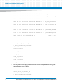
2.2.4
Configuring PXE
PXE determines which kernel and root file system image a blade gets from the server. The PXE
environment as well as the bootable images usually reside in the /tftpboot directory on the
server. The initial boot file is called pxelinux.0 and the PXE configuration directory is in the
/tftpboot/pxelinux.cfg. The default configuration file is called
/tftpboot/pxelinux.cfg/default.
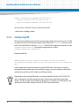
Example default file:
DEFAULT ATCA7365/kernel ramdisk_size=716800 console=ttyS0,9600n8
initrd=ATCA7365/ramdisk.image.gz root=/dev/ram0 ip=none ro pci=lastbus=255
quiet
In this configuration, the same images are served to all blades in the chassis. In order to
distinguish between blades and to serve different images, you can use different default files
and link them to different’ MAC addresses of different blades.
Depending on the particular BBS release, an example default file for the ATCA-7360/7365
may be contained in the BBS package (check the release notes applicable to your blade
release). This file contains all required kernel parameters. In order to use the default file, you
need to link it to the MAC address of the ATCA-7365 as described below.
30
Basic Blade Services Software on ATCA-7360/7365 Programmer’s Reference (6806800K42E)
Installing the Basic Blade Services Software
Example:
The following example shows how to set up the PXE environment for an ATCA-7360/7365
blade. This is done by creating a new default file and linking it to the MAC address of the ATCA7360/7365 boot Ethernet interface, which is 00:80:42:1d:da:07 in the example.
PXE expects that the file name should be prefixed with "01" and all the characters in the file
name are lower case letters.
Setting up the PXE Environment
Proceed as follows:
1. Make a new subdirectory in /tftpboot
#mkdir -p /tftpboot/ATCA7365
2. Copy the corresponding boot image and RPMs to this directory.
3. Set up a new default files in /tftpboot/pxelinux.cfg, for example
default.7365.
The contents of default.7365 are:
DEFAULT ATCA7365/kernel ramdisk_size=600000
console=ttyS0,9600 initrd=ATCA7365/ramdisk.image.gz
root=/dev/ram0 rw
4. Link the MAC address of the blade to its boot default file, for example:
#cd /tftpboot/pxelinux.cfg
#ln -s default.7365 01-00-80-42-1d-da-07
2.3
Installation Procedures
The following subsections list the different BBS installation procedures.
Basic Blade Services Software on ATCA-7360/7365 Programmer’s Reference (6806800K42E)
31
Installing the Basic Blade Services Software
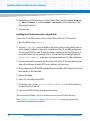
2.3.1
Configuring ATCA-7360/7365 for Diskless Client Boot of the BBS
Software
This section describes the steps you need to take for performing diskless client boot of the BBS
software.
Configuring BIOS for Diskless Client Boot
To configure BIOS for diskless client boot, proceed as follows:
1. Connect to the blade via the serial interface.
2. Power up or reboot the blade.
3. Quickly hold down the <F2> key on your keyboard until the BIOS menu appears.
In some versions of BIOS, after you press <F2> the BIOS alerts you whether to “load previous
values” for BIOS settings.
4. Select ADVANCED on the top menu.
5. Scroll down to BOOT FEATURES by using the arrow keys.
6. Press <ENTER>.
7. Make sure that the following settings are enabled:
Base-Interface Network boot or Front Panel Network Boot
(depending on the interface you want to boot from).
If any of these settings is disabled, enable the setting(s) and press <F10> or select
Exit Saving Changes. This will save the new settings and restart the BIOS.
After the restart, press <F2> to enter BIOS again and continue with the BIOS
configuration.
32
Basic Blade Services Software on ATCA-7360/7365 Programmer’s Reference (6806800K42E)
Installing the Basic Blade Services Software
8. Depending on which interface you want to boot from, put either Base Network
1, Base Network 2, or FrontPanel Network to the first position of the
Boot priority order list.
9. Save and exit.
Rebooting the Blade
To reboot a blade, proceed as follows:
1. Reboot the blade via:
Shelf manager
Opening and closing the lower handle switch on the face plate
Pressing the reset button on the face plate
2. Observe that the blade is getting a DHCP address and is loading the kernel and
ramdisk image:
Try to load: pxelinux.cfg/<address>
boot:
Loading <blade/module>/kernel..............
Loading <blade/module>/ramdisk-image.gz....
3. Once the blade has fully come up, log on to the serial console as root with the
default password root.
2.3.2
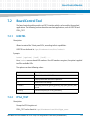
Installing BBS Software on Hard Disk Drive
This section describes how to install and boot the BBS software from hard disk. The BBS
software can be installed on the following hard disk types:
SAS/SATA hard disk drive installed on RTM or
SATA cube on front board (optional)
The installation process starts with the booting of an initial ramdisk via network. The initial
ramdisk is then used to copy (via TFTP) and interactively install the kernel, the root file system,
and other BBS software on the disk.
The following procedures describe these steps in detail.
Basic Blade Services Software on ATCA-7360/7365 Programmer’s Reference (6806800K42E)
33
Installing the Basic Blade Services Software
Configuring BIOS for Diskless Network Boot
To configure BIOS for network boot, proceed as follows:
1. Connect to the blade via the serial interface.
2. Power up or reboot the blade.
3. Quickly hold down the <F2> key on your keyboard until the BIOS menu appears.
4. Select ADVANCED on the top menu.
5. Scroll down to BOOT FEATURES by using the arrow keys.
6. Press <ENTER>.
7. Make sure that the following settings are enabled:
Base-Interface Network boot or Front Panel Network Boot
(depending on the interface you want to boot from).
If any of these settings is disabled, enable the setting(s) and press <F10> or select
Exit Saving Changes. This will save the new settings and restart the BIOS.
After the restart, press <F2> to enter BIOS again and continue with the BIOS
configuration.
8. Depending on which interface you want to boot from, put either Base Network
1, Base Network 2, or FrontPanel Network to the first position of the
Boot priority order list.
9. Save and exit.
Installing Files and Configuring TFTP on the ATCA-7360/7365
After the system has come up, install Linux with the following procedure:
1. Login as root.
2. Identify the Linux device name of the hard disk on which you want to install BBS.
To do so, enter fdisk -l. This displays available hard disks, their Linux device
names and also the storage capacity.
34
Basic Blade Services Software on ATCA-7360/7365 Programmer’s Reference (6806800K42E)
Installing the Basic Blade Services Software
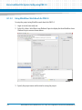
3. Run the linuxrc script from the /opt/bladeservices/tools directory:
./linuxrc
The hard disk installation begins by checking for necessary commands on the
system.
4. Enter the information requested by the script, such as the TFTP server address from
where the software is loaded, NTP server address, and time zone.
5. Above steps installs all the BBS packages that are available after tftpboot and Linux
Boot loader, on the hard disk.
Refer Installing BBS Using Hard Disk on page 127, for step-wise output of the installation and
configuration procedure.
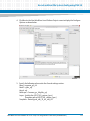
Performing the Final Configuration on the ATCA-7360/7365
The final configuration includes configuring the host name and password and setting the time
zone.
1. Configure the host name:
Choose a hostname for this machine [ ]
There is no default hostname. Enter a value here.
2. Configure the root password:
Enter new UNIX password:
Retype new UNIX password:
There is no default root password.
Now the boot loader grub is installed. After that you need to configure BIOS to boot from the
hard disk as described in the following procedure.
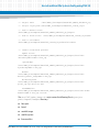
Configuring the ATCA-7360/7365 BIOS to Boot from Hard Disk
To configure BIOS on an ATCA-7360/7365 blade, proceed as follows:
1. Connect to the blade via the serial interface.
2. Power up or reboot the blade.
3. Quickly hold down the <F2> key on your keyboard until the BIOS menu appears.
Basic Blade Services Software on ATCA-7360/7365 Programmer’s Reference (6806800K42E)
35
Installing the Basic Blade Services Software
4. Select BOOT on the top menu.
5. Scroll down to BOOT OPTIONS by using the arrow keys.
6. Press <ENTER>.
7. Depending on the hard disk type and the location where the hard disk is installed,
make sure that the corresponding BIOS setting shown in the following table is
enabled.
Hard Disk
BIOS Menu and Setting Which Must Be Enabled
SAS hard disk installed on RTM
“Boot Features” -> "ARTM SAS boot"
If the desired setting was previously NOT enabled, enable the desired setting and
press <F10> or select Exit Saving Changes. This will save the new settings
and restart the BIOS. After the restart, press <F2> to enter BIOS again and continue
with the BIOS configuration.
8. Put the hard disk which you want to boot from to the first position of the Boot
priority order list.
9. Save and exit.
After a successful reboot, you can logon as root using the password you have
defined during the final configuration.
36
Basic Blade Services Software on ATCA-7360/7365 Programmer’s Reference (6806800K42E)
Installing the Basic Blade Services Software
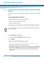
2.3.3
Installing BBS Software on On-Board USB Disk
The ATCA-7360/7365 BBS supports network boot via tftp. You can use flashrfsrc script to
install the root file system on the ATCA-7360/7365 on-board flash and to boot from it. The
flashrfsrc script performs the following tasks:
formats the ATCA-7360/7365 on-board flash device
transfers the kernel, root file system, and BBS packages from the tftp server to the onboard flash device
installs and configures the GRUB boot loader
Executing the flashrfsrc script will erase all the data existing on the on-board flash.
Configuring BIOS for Diskless Network Boot
To configure BIOS for network boot, proceed as follows:
1. Connect to the blade via the serial interface.
2. Power up or reboot the blade.
3. Quickly hold down the <F2> key on your keyboard, until the BIOS menu appears.
4. Select BOOT on the top menu.
5. Scroll down to BOOT OPTIONS by using the arrow keys.
6. Press <ENTER>.
7. Ensure that the following settings are enabled:
Base Network 1, Base Network 2, or FrontPanel Network; depending
on the interface you want to boot from.
If any of these settings is disabled, enable the setting(s) and press <F10> or select
Exit Saving Changes, to save the new settings and restart the BIOS. After the
restart, press <F2> to enter BIOS again and continue with the BIOS configuration.
Basic Blade Services Software on ATCA-7360/7365 Programmer’s Reference (6806800K42E)
37
Installing the Basic Blade Services Software
8. Depending on which interface you want to boot from, put either Base Network
1, Base Network 2, or FrontPanel Network to the first position of the
Boot priority order list.
9. Save and exit.
Installing Root File System on the on-board Flash
To install the OS and BBS software on the on-board flash of RTM-ATCA-7360 module:
1. Start the blade using tftp-boot.
2. Execute flashrfsrc script (available in the root directory of the blade) after an
initial netboot. It allows an automatic installation of the OS and BBS packages on
the on-board USB flash disk. Provide the device name on which the software is to
be installed when you are prompted for it. You can modify the configuration file
flashConfig.default as per your requirement and use it for the installation.
3. Enter the information requested by the script, such as the TFTP server address from
where the software is loaded, NTP server address, and time zone.
4. Above steps installs all the BBS packages that are available after tftpboot and Linux
Boot loader, on the hard disk.
5. Reboot the blade.
6. Press <F2> to configure the BIOS.
7. In the Boot menu, move onboard:USBHdd SMART eUSB to the first option in
the Boot Priority Order list.
8. Save and exit BIOS settings and continue booting.
After successful installation, the OS is loaded from the on-board USB flash disk drive.
Refer Appendix A, Installing and Configuring BBS, on page 127, for step-wise output of the
installation and configuration procedure.
38
Basic Blade Services Software on ATCA-7360/7365 Programmer’s Reference (6806800K42E)
Installing the Basic Blade Services Software
2.4
Upgrading the Software
Software updates are usually delivered as rpm-files. To install the files on the disk of the blade,
copy the new RPM file to the blade, stop the application using this rpm, remove the original
files (using the rpm -e <package> command) and install the newly copied rpm (using the
command rpm -Uvh <package-name> command).
To upgrade the BBS software for diskless clients, you have to delete the installation files in the
/tftpboot directory on the tftpserver, copy the new installation files into this directory, and
follow the instructions in Configuring ATCA-7360/7365 for Diskless Client Boot of the BBS Software
on page 32.
2.5
Adapting the BBS Software to Customer’s Needs
The BBS software structure allows a maximum flexibility with regards to customer’s
adaptations. Software packages can easily be installed into or removed from existing
installations.
The following adaptations are possible:
2.5.1
Modifying the NetBoot root file system
Modifying the hard disk installation
Modifying the hard disk installation procedure
Modifying the Configuration of the Artesyn-Supplied CGL Kernel
Modifying the NetBoot Root File System
The netBoot root file system is stored in the file ramdisk.image.gz on the TFTP server. In
order to change the system’s behavior regarding network booting blades, you have to modify
the root file system.
As root:
#
#
#
#
cd /tftpboot/<blade or module to be modified>
mkdir mnt
gunzip ramdisk.image.gz
mount -o loop ramdisk.image mnt
Basic Blade Services Software on ATCA-7360/7365 Programmer’s Reference (6806800K42E)
39
Installing the Basic Blade Services Software
# pushd mnt
# ..... /* make all modifications and enhancements: delete, add or
change files*/
# popd
# unmount mnt
# gzip -9 ramdisk.image.gz
The blade will now boot the modified root file system.
2.5.2
Modifying Hard Disk Installation
The hard disk installation can be changed after the blade has been installed or by modifying the
file rootfs.tar.gz prior to the installation. After modifying this file, you have to compute
and add the sha1 checksum of the modified root file system to the files.sha1sum in the
installation directory on the TFTP server.
The example below shows how to change the default login behavior.
# cd /tftpboot/...
(cd to the directory containing the
rootfs.tar.gz you want to modify)
# mkdir rootfs
# cd rootfs
# tar xzf ../rootfs.tar.gz
* Make your modifications and enhancements to the root filesystem
in the current directory
# tar czf ../rootfs.tar.gz .
# cd ..
# sha1sum rootfs.tar.gz
*Correct the sha1sum for rootfs.tar.gz in files.sha1.sum
2.5.3
Modifying the Hard Disk Installation Procedure
The hard disk installation procedure is based on the files.sha1sum in the installation
directory on the TFTP server. All packages which are copied to the blade during installation are
listed in the files.sha1sum together with their sha1sum. The standard installation process
accepts rpm, tar, and tgz files and all files that have "kernel" in the file name.
40
Basic Blade Services Software on ATCA-7360/7365 Programmer’s Reference (6806800K42E)
Installing the Basic Blade Services Software
The packages from files.sha1sum are installed in the same sequence as listed in the file
files.sha1sum. The installation process re-calculates the sha1sum of the packages on the
blade and compares it to the sha1sum determined by files.sha1sum. This ensures a
protection against errors and faults during file transmission. The user will be notified in case of
mismatch. In that case, you have to repeat the installation procedure.
The root file system must precede the rpm files in the files.sha1sum file.
2.5.4
Modifying the Configuration of the Artesyn-Supplied PNE Linux
Kernel
The current kernel configuration of a running ATCA-7360/7365 installation can be retrieved
using the Linux command zcat /proc/config.gz or from
ATCA7365_custom_layer/template/board/atca7365/linux/atca7365.cfg in
the LSP directory of the Release package.
To modify the configuration of the CGL kernel supplied by Artesyn, consult your local Artesyn
sales representative for assistance and further information.
Basic Blade Services Software on ATCA-7360/7365 Programmer’s Reference (6806800K42E)
41
Installing the Basic Blade Services Software
42
Basic Blade Services Software on ATCA-7360/7365 Programmer’s Reference (6806800K42E)
Chapter 3
Linux Distribution Description
3.1
Distribution Description
The BBS for the ATCA-7360/7365 is based on Wind River Enterprise Linux 3.0, which is a Linux
distribution built on Linux 2.6.27 kernel technology.
3.2
Reliability
The hard disk installation is configured to use the journaling file system ext3. In this
distribution majority of errors that are caused due to improper shutdown are fixed
automatically during the boot process. Catastrophic errors that cannot be fixed automatically
will yield to a command prompt, allowing the super user to execute the fsck command on the
affected partition.
3.3
Login
A Linux shell can be accessed via the face plate serial port.
If you use a serial console or terminal emulator, the serial/RTM port settings are 9600 baud, no
parity, 8 data bits, and 1 stop bit.
If you use secure shell server, it starts in run levels 2–5 and listens on all the Ethernet interfaces.
Root login for ssh is not permitted, you need to log in as user "admin".If you use SSH, refer
Network Services Configuration on page 47 for default IP address assignments.
If you want to login as root via SSH, you need to first configure SSH using the console serial
port. Set PermitRootLogin in the file /etc/ssh/sshd_config to yes. For this to take
effect you must either reboot the blade or run the command /etc/init.d/ssh restart.
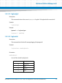
The following table lists available default login accounts.
Login Name
Password
Description
admin
emerson
Non-privileged user account
root
root
Privileged user account
Basic Blade Services Software on ATCA-7360/7365 Programmer’s Reference (6806800K42E)
43
Linux Distribution Description
3.4
Long POST/Diagnostics
The long POST (Power-On Self test) is an extension to the standard POST which the ATCA7360/7365 executes after power-up. It is executed during the booting of the Linux operating
system and includes higher-level tests. This section describes which tests are by default
executed during the long POST, how to obtain the results of these tests and how to add your
own test routines.
3.4.1
Default Test Routines
The long POST test routines are implemented as Linux scripts which are invoked during the
Linux boot phase. The test scripts which are to be executed need to be defined in the IPMI boot
parameter variable runLP or as additional parameter in the kernel command line
(runLP=…,…,). Further details are given in Configuring the Long POST Behavior on page 45.
Each test routine displays the test status on the console and writes it to the Linux log module
(via logger). Furthermore, each test routine writes status information to the IPMI sensor
"System Firmware Progress" (type 0xF0). The used event data values are Artesyn-specific. The
following table provides details.
Table 3-1 Long POST Standard Test Routines - Generated IPMI Data
Action
Data Written to System Firmware Progress Sensor
Test routine is started
Offset 0: 0x02
Offset 1: 0xFD
Offset 2: 0x1E
Tests routine detects an error.
Offset 0: 0x00
Offset 1: 0xFD
Offset 2: 0x1E
44
Basic Blade Services Software on ATCA-7360/7365 Programmer’s Reference (6806800K42E)
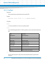
Linux Distribution Description
The following table lists the names of the default long POST test routines and describes which
tests each routine performs.
Table 3-2 Long POST Default Test Routines
3.4.2
Test Routine Name
Description
cpuspeed
This tool gives an overview on the active performance governors and the
frequency per core.
memSize
Checks the amount of memory physically installed and the memory
seen by the Operating system.
rtctest
Tests the functionality of the real time clock.
eccTest.sh
This scripts tests checks the ECC Error counter in the memory controller.
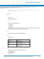
Configuring the Long POST Behavior
The names of the test scripts which are to be executed have to be defined in the IPMI system
boot parameter variable runLP as a comma-separated list, for example as follows:
runLP=cpuspeed,memSize.sh,rtctest,eccTest.sh
The scripts are expected to be located in the following directory:
/opt/bladeservices/tools/LP. So in order to add your own scripts, simply add an entry
to the IPMI boot variable runLP or add an appropriately defined kernel boot parameter runLP
and place the script(s) in /opt/bladeservices/tools/LP. Depending on your system
configuration, you may want to design your test scripts to generate console output, write to
the log module and store any results in the IPMI System firmware progress sensor as done by
the default test scripts.
The IPMI boot parameter can be set by using the hpm command bootparamset (hpm -c
bootparamset).
When Linux is booted, the Linux start-up script /etc/init.d/LPmain.sh is executed. It
reads and analyses the IPMI boot parameter variable runLP and invokes the listed test scripts
(if any) in the given order. For more advanced customizations, you may want to modify the
/etc/init.d/rd.d/LPmain.sh script.
Basic Blade Services Software on ATCA-7360/7365 Programmer’s Reference (6806800K42E)
45
Linux Distribution Description
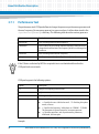
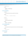
The LPmain.sh provides the following options:
Table 3-3 Long POST Script LPmain.sh - Options
3.5
Option
Description
start
Starts the Long POST for the specified test cases.
status
Gives information about the test cases to be executed during long POST and
shows whether longPOST is switched on.
enableLP
Enables the long POST. The Long POST will be executed during the next OS
startup.
disableSP
Disables the long POST. The long POST will not be executed during the next OS
startup.
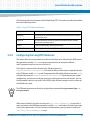
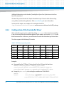
Linux Services Initialization
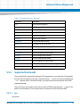
Table 3-4 describes the generic Linux run levels. Table 3-1 describe the services configured to
start in the various Linux run levels. Per default, the blade first runs run level S and then boots
into run level 3 as configured by the factory.
Table 3-4 Generic Linux Run Levels
46
Run Level
Description
S
Startup
0
Halt system
1
Single-user mode
2
Multiuser mode
3
Multiuser mode with network (default)
4
Not used
5
Not used
6
Reboot system
Basic Blade Services Software on ATCA-7360/7365 Programmer’s Reference (6806800K42E)
Linux Distribution Description
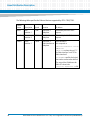
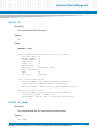
3.5.1
RC Scripts
In addition to the rc-scripts of the Wind River PNE 3.0 Linux configuration the following
start/stop scripts are added to ATCA-7360/7365.
Run
Level
Script Name
Description
rc0.d
s57bbsvlan
Stops the hpmagent.
rc3.d
s01bbsrpms
Installs bbs-rpms during initial blade startup, for example,
after blade installation or boot via network boot.
s02bbsinit
Starts boardctrl driver and the optional persistant memory
drivers (pram and sfmem when the optional memory
module is installed).
s03longPost
Performs some basic blade tests, before most of the OS
services are started.
s09hpm
Starts the hpmagent.
s10ethDevOrdering
Performs the eth-device reordering and renaming.
s57bbsvlan
Configures ip-addresses for the fabric interfaces and brings
up the base and fabric interfaces.
S99osBootSensor
On successful boot an IPMI event "OS Boot - Boot success"
will be sent.
k05hpm
Stops the hpmagent.
rc6.d
3.6
Network Services Configuration
The following sections describe the default configuration for network services.
3.6.1
ATCA-7360/7365 Ethernet Interfaces
The ethernet devices, such as eth0, eth1, and eth2 in Linux distribution are renamed to more
meaningful name in ATCA-7360/7365, such as base1, base2, and fabric1. This renaming is
done in the /etc/init.d/ethDevOrdering.sh script, before the network startup.
Basic Blade Services Software on ATCA-7360/7365 Programmer’s Reference (6806800K42E)
47
Linux Distribution Description
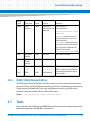
The following table specifies the Ethernet devices supported by ATCA-7360/7365.
Device
Name
Description
Speed
Location
IP address
base1
Base
Interface 1
1GbE
Base blade ->
Backplane
Obtained by the DHCP client
request.
base2
Base
Interface 2
1GbE
Base blade ->
Backplane
Obtained by the DHCP client
request.
fabric1
Fabric
Interface 1
10GbE
Base blade ->
Fabric Interface on
Backplane
Static IP address.
It is computed as:
192.168.<fabricIf>.<slotn
umber*10>
fabricIf can have value of; ’11"
for Fabric Interface 1 and "12" for
Fabric Interface2.
slotnumber specifies the logical
slot number converted to decimal.
The setup of the IP Addresses for
Fabric IF is done in the
/etc/init.d/bbsvlan.sh file.
48
Basic Blade Services Software on ATCA-7360/7365 Programmer’s Reference (6806800K42E)
Linux Distribution Description
Device
Name
fabric2
Description
Speed
Location
IP address
Fabric
Interface 2
10GbE
Base blade ->
Fabric Interface on
Backplane
Static IP address.
It is computed as:
192.168.<fabricIf>.<slotn
umber*10>
fabricIf can have value of; ’11"
for Fabric Interface 1 and "12" for
Fabric Interface2.
slotnumber specifies the logical
slot number converted to decimal.
The setup of the IP Addresses for
Fabric IF is done in the
/etc/init.d/bbsvlan.sh file.
3.6.2
front
Front Panel
Interface
1GbE
Base blade
No IP address assigned.
update
Update
Channel
interface
1GbE
Base blade
No IP address assigned.
rtm1
RTM 1
1GbE
RTM (optional)
No IP address assigned.
.......
..........
........
......................
rtm6
RTM 6
1GbE
RTM (optional)
NOTE: The devices on the bottom
are named from botton to top on
the face blade.
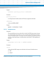
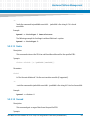
IXGBE 10GB/s Network Driver
The IXGBE device driver for the fabric interfaces creates one receive and one transmit queue
per each CPU core. Usually all IRQs are routed to core0. If this is not wanted (e.g. when having
a huge amount of network traffic) the script /opt/bladeservices/set_irq_affinity can be
executed. It will then assign the IRQs to different CPU cores.
Syntax:
3.7
set_irq_affinity <fabric inferface name>
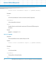
Tools
This section describes CPUSpeed and IPMIBPAR tools that can be used to change the processor
performance governors and IPMI Boot Parameter list.
Basic Blade Services Software on ATCA-7360/7365 Programmer’s Reference (6806800K42E)
49
Linux Distribution Description
3.7.1
Performance Tool
The performance tool, CPUSpeed allows to change the processor performance governors and
the core frequency (for userspace governor) on a per core base. It utilizes data stored in the
/sys/device/system/cpu directory. The following table describes various governors.
Governor
Description
Performace
Core is running with maximum frequency.
Ondemand
Cores in idle state are running at lowest frequency. When the core is
changed to the utilized state, the frequency of the core is changed to
maximum.
Powersave
Core is running with minimum frequency.
Userspace
Core frequency can be adjusted by the user (in steps).
If the P-States are limited by BIOS the required driver is not loaded and therefore the
CPUSpeed tool can not work.
CPUSpeed supports the following options:
Option
Description
-d
Dump CPU Frequency/Governor Info
-h
Help
-p
Print supported governors
-s
Set governor/frequency. It supports the following options:
-c : Specifies the core. Valid values are 0 .. 15. Omitting this option
means, all cores.
-f : Specifies the frequency. Valid values are 1596000 .. 2129000.
This parameter is ignored except for ’userspace governor’.
-g : Specifies governors, such as performance, powersave,
ondemand, and userspace.
Example:
50
Basic Blade Services Software on ATCA-7360/7365 Programmer’s Reference (6806800K42E)
Linux Distribution Description
root@atca7360:/proc/boardinfo# cpuspeed -h
3.7.2
IPMIBPAR
The IPMIBPAR tool can be used to change the IPMI Boot Parameter list when Linux is up and
running. It supports the following options:
Option
Description
-d
Enable debug output.
-a xx
IPMB Address, if not present local IPMC is used.
-i
Get device ID.
-g
Get IPMI Boot Parameter USER area.
-s file
Store IPMI Boot Parameter (USER area), read from file.
-h
Help.
The following example describes the steps required to change the BootOrder from SAS-HDD
to Base Network1.
1. Read the IPMI boot parameter USER area from IPMC.
root@ATCA7360:/etc/sysconfig/network-scripts# ipmibpar -g
ipmibpar - Version 1.02 - IPMI Boot Parameter Demo
Copyright 2008 Emerson Network Power Embedded Computing Inc.
Read System Boot Options from USER area (local IPMC)
Hexdump IPMI Boot Parameter:
Size = 218 (0xda)
0000 d6 00 62 61 75 64 72 61 74 65 3d 39 36 30 30 00
<..baudrate=9600.>
0010 75 73 62 3d 66 70 5f 6f 6e 2c 72 74 6d 5f 6f 6e
<usb=fp_on,rtm_on>
0020 2c 6f 6e 62 6f 61 72 64 5f 6f 6e 00 6f 73 5f 62
<,onboard_on.os_b>
0030 6f 6f 74 5f 77 61 74 63 68 64 6f 67 3d 6f 66 66
<oot_watchdog=off>
0040 2c 31 30 2c 72 65 73 65 74 00 66 72 6f 6e 74 6e
<,10,reset.frontn>
Basic Blade Services Software on ATCA-7360/7365 Programmer’s Reference (6806800K42E)
51
Linux Distribution Description
0050 65 74 5f 62 6f 6f 74 3d 6f 6e 00 62 61 73 65 6e
<et_boot=on.basen>
0060 65 74 5f 62 6f 6f 74 3d 6f 6e 00 61 72 74 6d 5f
<et_boot=on.artm_>
0070 6e 65 74 5f 62 6f 6f 74 3d 6f 66 66 00 61 72 74
<net_boot=off.art>
0080 6d 5f 73 61 73 5f 62 6f 6f 74 3d 6f 6e 00 61 72
<m_sas_boot=on.ar>
0090 74 6d 5f 66 63 5f 62 6f 6f 74 3d 6f 66 66 00 62
<tm_fc_boot=off.b>
00a0 6f 6f 74 5f 6f 72 64 65 72 3d 73 61 73 68 64 64
<oot_order=sashdd>
00b0 2c 62 61 73 65 6e 65 74 31 2c 73 61 73 68 64 64
<,basenet1,sashdd>
00c0 2c 75 73 62 6f 6e 62 6f 61 72 64 2c 66 72 6f 6e
<,usbonboard,fron>
00d0
74 6e 65 74 00 00 00 00 29 4f
<tnet....)O>
IPMI Boot Parameter:
baudrate=9600
usb=fp_on,rtm_on,onboard_on
os_boot_watchdog=off,10,reset
frontnet_boot=on
basenet_boot=on
artm_net_boot=off
artm_sas_boot=on
artm_fc_boot=off
boot_order=sashdd,basenet1,sashdd,usbonboard,frontnet
2. Save the received IPMI Boot Parameter list into a file (for example, bootparam.log) and
change the boot order as follow.
baudrate=9600
usb=fp_on,rtm_on,onboard_on
os_boot_watchdog=off,10,reset
52
Basic Blade Services Software on ATCA-7360/7365 Programmer’s Reference (6806800K42E)
Linux Distribution Description
frontnet_boot=on
basenet_boot=on
artm_net_boot=off
artm_sas_boot=on
artm_fc_boot=off
boot_order=basenet0,sashdd,basenet1,sashdd,usbonboard,frontnet
3. Write the IPMI parameter list file (for example, bootparam.log).
ipmibpar -s <filename>
3.7.3
CoreTemp
At /opt/bladeservices/tools you can find a script named coretempdump which
reads and displays the CPU temperature on a per core base. It also shows whether the
temperature exceeds the max allowed core temperature (indication for CPU throttling).
Syntax: coreTempDump.sh
3.8
VGA Support
Variants of the ATCA-7360/7365 boards are equipped with an optional VGA adapter module.
This device will shows up as, "VGA compatible controller: XGI Technology Inc. (eXtreme
Graphics Innovation) Volari Z11M" in lspci.
3.8.1
Software Support
The provided kernel or Root File System supports the frame buffer devices, which is an
abstraction layer for the graphics hardware. It represents the frame buffer of the video
hardware and allows application software to access the graphics hardware through a well
defined interface. So the software does not need to understand the low-level hardware
register.
The device is accessed through the special device nodes, which is located in the /dev directory
as shown below:
/dev/fb*
Basic Blade Services Software on ATCA-7360/7365 Programmer’s Reference (6806800K42E)
53
Linux Distribution Description
Additional information can be found at "framebuffer.txt from Geert Uytterhoeven in the linux
kernel Documentation".
The Root File system includes the "Simple DirectMedia Layer" libraries which allow writing
cross-platform multimedia applications. Refer www.libsdl.org for more information.
To test the VGA adapter, an example sdl- is installed in the RFS at
/opt/bladeservices/tools/vgatest and its sources can be found in the BBS package.
3.8.2
Configuration of the Framebuffer Driver
The framebuffer support can be enabled by adding vga=<mode> to the kernel command line.
If you are not sure about the resolution support of your monitor, you can use vga=ask in the
kernel command line. In this case, you will be asked to select the resolution type at boot time.
The driver supports the following VGA modes:
Table 3-5 VGA driver supporting modes
Colours
640x400
640x480
800x600
1024x768
1152x864
1280x1024
1600x1200
4 bits
?
?
0x302
?
?
?
?
8 bits
0x300
0x301
0x303
0x305
0x161
0x307
0x31C
15 bits
?
0x310
0x313
0x316
0x162
0x319
0x31D
16 bits
?
0x311
0x314
0x317
0x163
0x31A
0x31E
24 bits
?
0x312
0x315
0x318
?
0x31B
0x31F
Examples:
54
Command line for TFTP Boot. The kernel asks for the VGA mode at boot time:
DEFAULT ATCA7365/kernel ramdisk_size=716800
console=ttyS0,9600n8 initrd=ATCA7365/ramdisk.image.gz
root=/dev/ram0 ip=none ro vga=ask pci=lastbus=255 quiet
Excerpt of grub.config is for setting the resolution to 1024x768x16.
serial
...
kernel
/boot/bzImage vga=0x317 console=ttyS0,9600
root=UUID=10cc71977-c88d-48f6-9dd2-331bece027d3
Basic Blade Services Software on ATCA-7360/7365 Programmer’s Reference (6806800K42E)
Linux Distribution Description
initrd
ro pci=lastbus=255 idle=nomwait quiet
..
If you have the ATCA-7360/7365 blade without VGA adapter, you can keep the kernel
command line parameter vga=xxx in your grub- or tftp- configuration. In this case, the
parameter will be ignored and booting will be continued without interruption.
3.9
Network Performance
In case, your application handles a lot of UDP/TCP-IP traffic on the base and fabric interfaces,
you should modify your configuration accordingly.
Configuration for Increasing the Network Performance
Follow these steps to handle the UDP/TCP-IP traffic:
1. Increase the network stack size:
sysctl -w net.core.rmem_default=1000000
sysctl -w net.core.wmem_default=1000000
sysctl -w net.core.rmem_max=1000000
sysctl -w net.core.wmem_max=1000000
2. Normally core0 of the first CPU handles all interrupts. Due to this, core0 will get overloaded
and other cores may remain idle. To avoid this situation, set_irq_affinity
<network interface> script can be used to clear the receiving and transmitting
queues of the Ethernet controller. For example:
set_irq_affinity fabric1
The script can be found at /opt/bladeservices/tools/set_irq_affinity.sh.
3. The receive and transmit ringsize buffer should be enlarged:
ethtool –G rx <network interface> and ethtool –G tx <network
interface>
4. The calculation of the receive checksum can be offloaded.
ethtool –K <network interface> rx on
Basic Blade Services Software on ATCA-7360/7365 Programmer’s Reference (6806800K42E)
55
Linux Distribution Description
5. Limit the C-States in BIOS and OS in order to avoid the cores going away to sleep. This can
be done by adding “idle=nomwait” to the kernel command line and via BIOS settings.
(See BIOS->Advanced->CPU Configuration)
6. The Intel 82576 2x1GbE Controller on the Base Interface can be configured to use more
than one receive and transmit queues. Eight queues are used by setting the RSS parameter
to '0'. (See also Readme file of the Intel 82576)
Example of the kernel command line used for network boot:
DEFAULT ATCA7365/kernel ramdisk_size=716800 vga=0x317
console=ttyS0,9600 initrd=ATCA7365/ramdisk.image.gz root=/dev/ram0
ip=none ro idle=nomwait pci=lastbus=255 igb.RSS=0,0,0,0,0,0,0,0
igb.InterruptThrottleRate=3000,3000,3000,3000,3000,3000,3000,3000
The igb driver is now configured to support multiple queues.
By default, the Intel 82599 2x10GbE is already configured to use up to 32 queues.
56
Basic Blade Services Software on ATCA-7360/7365 Programmer’s Reference (6806800K42E)
Chapter 4
Firmware Upgrade Facility
4.1
Overview
The Firmware Upgrade Facility (FUF) provides a uniform way to upgrade firmware on Artesyn
hub blades and node blades. It consists of a Firmware Upgrade Command-line Utility (FCU),
flash device drivers, and specially prepared firmware recovery image files. On the ATCA7360/7365 FUF allows you to upgrade the following firmware types:
4.2
BIOS firmware
IPMC firmware
MMC firmware on RTM
FPGA image
Firmware Recovery Image Files
FCU supports specially prepared firmware recovery image (FRI) files as well as firmware images
in the HPM.1 format. HPM.1 is a PICMG standard to upgrade IPMCs.
By default, the image files for the current hardware configurations are loaded as part of the BBS
software in /opt/bladeservices/rom when the blade-specific firmware support
packages are installed.
The following image files are currently supported.
Filename
Description
atca-7365-cpu-<version>.fri
BIOS image for ATCA-7360/7365
atca-7365-ipmc-<version>.hpm
IPMC firmware for ATCA-7360/7365
atca-7365-ipmc-boot<version>.hpm
IPMC boot loader for ATCA-7360/7365
atca-7365-fpga-<version>.hpm
FPGA image for ATCA-7360/7365
atca-7360-artm-<version>.hpm
IPMC Firmware for ARTM
atca-7360-artm-boot<version>.hpm
IPMC boot loader for ARTM
Basic Blade Services Software on ATCA-7360/7365 Programmer’s Reference (6806800K42E)
57
Firmware Upgrade Facility
4.3
Backup Concept
The BIOS firmware for the ATCA-7360/7365 is stored in redundant, persistent memory
devices. This allows the firmware image in one bank to serve as a backup for the other bank.
This is particularly useful for firmware upgrades.
During normal operation, the CPU on the ATCA-7360/7365 determines which bank to boot
from based on a chip select signal controlled by the IPMC. This bank is considered the active
boot device. FCU will only allow you to upgrade an inactive device. FUF allows you to upgrade
only the BIOS boot bank from which the blade has not booted. This means that you need to
reboot the blade in case you want to upgrade both the banks of the BIOS flash. The BIOS
firmware image can be programmed via the payload by using FUF or via IPMC.
The IPMC firmware consists of a boot loader as well as an active and a stand-by IPMI firmware.
The boot loader maintains both the active and stand-by firmware in the flash memory of the
ATCA-7360/7365. Please note that the BootLoader Firmware is not installed in the BBS by
default, as the BootLoader update must be perfomed on Artesyn request only.
Each time the IPMC firmware is upgraded, the most recent firmware version is kept in flash
memory and the older firmware version is overwritten by the new one. Once the new IPMI
firmware is programmed, the IPMC resets itself to boot from the new image. The boot loader
validates the new IPMC firmware. Provided the IPMC can power up successfully the current
image is made active and the previously active image is made backup. In case of power-up
failures, the boot loader automatically recovers from crisis and boots from the previous image.
The FPGA bank can be updated via FCU or IPMC. This means that a corrupt FPGA image can be
restored using IPMC.
The following sample output displays the information regarding BIOS, IPMI, and FPGA.
Depending on your setup, you may get a different output.
fcu -q
********************[[[[[REPORT BEGIN]]]]]********************
OPERATION : Query
RESULT
: SUCCESS
MESSAGE
: Device
Part number
58
: atca-7360-cpu
: 0106865F08A....
Basic Blade Services Software on ATCA-7360/7365 Programmer’s Reference (6806800K42E)
Firmware Upgrade Facility
Part revision
: R1.2.
BANK
: A
Firmware Name
: AMI-BIOS
Firmware Version
: 1.0.0
Marked for next use : no
--> Installed BIOS Version on Bank0
BANK
: B
Firmware Name
: AMI-BIOS
Firmware Version
: 1.0.0
Marked for next use : yes
--> Installed BIOS Version on Bank1
OPERATION : Query
RESULT
: SUCCESS
MESSAGE
: Device
: atca-7360-hpm.1-ipmc
Part number
: 0106865F08A....
Part revision
: R1.2.
BANK
: A - Operational
Firmware Name
: H8S-AMCc F/W
Firmware Version
: 2.0.00000007
--> Installed IPMI FW on Bank0
BANK
: B - Rollback
Firmware Name
: H8S-AMCc F/W
Firmware Version
: 2.0.00000007
--> Installed IPMI FW on Bank1
Basic Blade Services Software on ATCA-7360/7365 Programmer’s Reference (6806800K42E)
59
Firmware Upgrade Facility
BANK
: D - Operational
Firmware Name
: H8S-AMCc B/L
Firmware Version
: 2.0.00000006
--> Installed IPMI FW Boot Loader
BANK
: G - Operational
Firmware Name
: H8S-AMCc F/I
Firmware Version
: 0.0.00000000
--> Internal IPMI Bank (FRU Info) No subject to be updated!
BANK
: J - Operational
Firmware Name
: H8S-AMCc F/C
Firmware Version
: 0.0.00000000
--> Internal IPMI Bank (FRU Info Carrier) No subject to be updated
BANK
: M - Operational
Firmware Name
: FPGA
Firmware Version
: 0.0.0000000D
--> Installed FPGA Version
BANK
: P - Operational
Firmware Name
: BIOS
Firmware Version
: 1.0.00000000
--> Installed BIOS Version (seen by IPMC)
BANK
: S - Operational
Firmware Name
: BIOS
Firmware Version
: 0.0.00000000
--> Second BIOS Bank (currently not seen by IPMC)
60
Basic Blade Services Software on ATCA-7360/7365 Programmer’s Reference (6806800K42E)
Firmware Upgrade Facility
OPERATION : Query
RESULT
: SUCCESS
MESSAGE
: Device
: artm-7360-hpm.1-ipmc
Part number
: unknown
Part revision
: unknown
IPMI address
: MMC=0x72
BANK
: A - Operational
Firmware Name
: AVR-AMCm F/W
Firmware Version
: 1.51.00000002
--> Installed IPMI FW for ARTM on Bank1
BANK
: B - Rollback
Firmware Name
: AVR-AMCm F/W
Firmware Version
: 1.51.00000002
--> Installed IPMI FW for ARTM on Bank2
BANK
: D - Operational
Firmware Name
: AVR-AMCm B/L
Firmware Version
: 1.51.00000001
--> Installed IPMI Booter FW for ARTM
********************[[[[[ REPORT END ]]]]]********************
Basic Blade Services Software on ATCA-7360/7365 Programmer’s Reference (6806800K42E)
61
Firmware Upgrade Facility
4.4
fcu—Firmware Upgrade Command-Line Utility
Description
The Firmware Upgrade Command-line Utility (FCU) allows you to
Query the current versions of firmware installed on the ATCA-7360/7365 and determine
which firmware devices are active
Verify that a specified upgrade image is sound and compatible with the current hardware
Upgrade a firmware image
Mark a device to be used as the boot source on the next reset
Show the version of a specified firmware image file and compare the version of a specified
firmware image file with the version of an installed firmware image
By default, the FCU binary executable is installed in /opt/bladeservices/bin. This
directory has been added to the PATH environment variable.
FCU works in conjunction with device drivers created specifically for the flash devices on
Artesyn blades.
The FCU verify and upgrade operations require specially prepared FRI or HPM files (see
Firmware Recovery Image Files on page 57).
FCU also relies on the Hardware Platform Management Agent daemon to interact with the
local IPMC. Most commands will fail if the HPM Agent is not running. For information on
configuring and running HPM Agent, see Chapter 5, Hardware Platform Management, on page
71.
Synopsis
fcu --help
fcu --version
fcu -q [-d <device-id>]
fcu -v -f <filename>
fcu -u -f <filename>
fcu -a -f <filename>
62
Basic Blade Services Software on ATCA-7360/7365 Programmer’s Reference (6806800K42E)
Firmware Upgrade Facility
fcu -m -b <bank-letter> -d <device-id>
Parameters
-a
--full-upgrade
This option is a shortcut for performing the verify, upgrade, and mark operations. The file
option -f is required. This option should not be combined with other operations.
-b <bank-letter>
--bank=<bank-letter>
Specifies the bank to mark for next boot, where <bank-letter> is the letter designating a
specific bank. For BIOS banks, possible values are A and B. For FPGA images, possible values are
B (default EEPROM) and C (user-programmable EEPROM). This option is used with the mark
operation. Use the query option -q to display available banks.
-d <device-id>
--device=<device-id>
Specifies a target firmware device, where <device-id> is the name of the device. This option
is used with the mark or query operations. Device ID values vary by hardware. You can display
supported devices on a given blade by using fcu --help. Currently supported values are
listed in the following table.
Device ID
Description
atca-7360-cpu
BIOS firmware image on ATCA-7360/7365
atca-7360-hpm.1-ipmc
IPMC firmware image on ATCA-7360/7365
artm-7360-hpm.1-mmc
MMC firmware image on RTM
atca-7360-fpga
FPGA image
-f <filename>
--file=<filename>
Specifies the FRI file, where <filename> is the complete path and filename of the image file.
This option is used with the verify and upgrade operations.
Basic Blade Services Software on ATCA-7360/7365 Programmer’s Reference (6806800K42E)
63
Firmware Upgrade Facility
--force
This option allows the installation of images with non-matching part-number and part-revision
FRU data fields. This option should be used with extreme caution only because installing an
incompatible image on a device may render it inoperable.
--help
Displays a brief message describing command usage. It also displays a list of the devices
supported on the blade.This option is exclusive and should not be used with other options.
This option needs a target destination -t argument added when working with the IPMC or
ARTM.
-m
--mark
Tells FCU to set the boot select so that on the next boot the specified firmware bank will be
active. When mark is combined with the upgrade operation, there is no need to specify a bank;
the bank just upgraded will be marked. Otherwise, you must specify a bank and a device.
Currently, the mark operation only supports CPU firmware devices.
-q
--query
Tells FCU to return firmware information for a specific device (if used with -d) or information
about all firmware devices. The query operation is exclusive and is not intended to be
combined with other operations.
-s
show
Shows detailed information about a specified file. The information shown includes for example
image type, version, manufacturer name etc. This command may be useful before a firmware
upgrade to determine the version of a new image file.
-u
--upgrade
64
Basic Blade Services Software on ATCA-7360/7365 Programmer’s Reference (6806800K42E)
Firmware Upgrade Facility
Tells FCU to upgrade the currently inactive bank of the device specified by the target FRI file.
The file option -f is required. The upgrade operation may be combined with the verify and
mark operations.
-v
--verify
Tells FCU to verify the image file specified by the required -f option. This operation verifies that
the specified file is sound and compatible with the current hardware. The verify operation may
be combined with the upgrade and mark operations.
--version
Displays version information for the utility. This option is exclusive and should not be used with
other options.
Usage
Some FCU options can be combined. Some options are exclusive. The following list describes
the valid option combinations:
--full-upgrade --file=<filename>
--help
--mark --bank=<bank-letter> --device=<device-id>
--query
--query --device=<device-id>
--show --file=<filename>
--upgrade --file=<filename>
--upgrade --mark --file=<filename>
--upgrade --file=<filename>
--verify --file=<filename>
--verify --upgrade --file=<filename>
--verify --upgrade --mark --file=<filename>
--version
Basic Blade Services Software on ATCA-7360/7365 Programmer’s Reference (6806800K42E)
65
Firmware Upgrade Facility
Multi character options may be abbreviated so long as they are unique. For example, --full
is equivalent to --full-upgrade. Typing --ver, however, will not work since it matches
both --verify and --version.
Single-character options may be combined without repeating the hyphen, as in these
examples:
fcu –vf /opt/bladeservices/rom/<filename>
fcu –q –d <device-id>
fcu –q –d <device-id>
fcu –mb a –d <device-id>
Options are not case-sensitive. For example, --help is equivalent to --HeLp. However,
option arguments, such as filename and device ID, are case-sensitive.
When upgrading firmware, it is strongly recommended that you upgrade only one device at a
time. While FCU performs many checks during upgrade to ensure success, if something goes
wrong and both firmware banks become corrupted, the blade will be inoperable.
4.5
Upgrading a Firmware Image
This section describes recommended procedures for upgrading firmware devices. The
procedures for upgrading BIOS and IPMC differ slightly.
The upgrade fails if the following is not taken into consideration:
Upgrade only one bank at a time, then reboot and verify the upgrade using the query option.
If the upgrade fails and both banks become corrupted for any reason, the ATCA-7360/7365
will be rendered inoperable.
To prepare the ATCA-7360/7365 for a BIOS upgrade, the dip-switches of the ATCA7360/7365 must be set such that all BIOS flashes are writable. This is the default
configuration. Refer to the ATCA-7360/7365 Installation and Use guide for further details
about dip switch settings.
66
Basic Blade Services Software on ATCA-7360/7365 Programmer’s Reference (6806800K42E)
Firmware Upgrade Facility
4.5.1
BIOS Upgrade
The BIOS can only be upgraded from the ATCA-7360/7365 on which the BIOS is running. You
have to upgrade the BIOS by using fcu.
Upgrading the BIOS Firmware
Follow these steps to upgrade the BIOS. The shown file names and paths are only meant as an
example and should be replaced with file names and paths applicable to your configuration.
1. Query the current BIOS firmware images on the blade.
fcu -qd atca-7360-cpu
2. Show the version of the new BIOS file (to verify that it has actually a newer version
than the already installed BIOS)
fcu --show -f /opt/bladeservices/rom/atca-7365-cpu<version>.fri
3. Upgrade the firmware image,
fcu --upgrade -f /opt/bladeservices/rom/atca-7365-cpu<version>.fri
FCU writes the new image and then reads back the image and performs a binary
compare to ensure that the write was successful. If the upgrade was not successful,
you will see an error message. Try the upgrade again. If it is still not successful,
contact your Artesyn representative.
4. Query the new image to ensure that the version information is correct,
fcu -qd atca-7360-cpu
5. Mark the new image as active so that it will be used for the next boot, for example:
fcu --mark -b <bank-letter> -d atca-7360-cpu
where <bank-letter> is the letter of the upgraded bank, for example: a
Note: It is highly recommended to power-cycle the blade after an BIOS upgrade so
that the complete image is re-read.
Basic Blade Services Software on ATCA-7360/7365 Programmer’s Reference (6806800K42E)
67
Firmware Upgrade Facility
4.5.2
IPMC Upgrade
Upgrading the IPMC Firmware
Follow these steps to upgrade an IPMC. The shown file names and paths are only meant as an
example and should be replaced with file names and paths applicable to your configuration.
The general procedure to upgrade the MMC image of an RTM is the same, except that you
need to use artm-7360-hpm.1-ipmc as device ID.
1. Query the current IPMC firmware images on the blade.
fcu -q -d atca-7360-hpm.1-ipmc
2. Show the version of the new IPMC file (to verify that it has actually a newer version
than the already installed image)
fcu --show -f /opt/bladeservices/rom/atca-7365-ipmc<version>.hpm
3. Upgrade the firmware image,
fcu --upgrade -f /opt/bladeservices/rom/atca-7365-ipmc<version>.hpm
Once the new IPMI firmware is programmed, the IPMC resets itself to boot from the
new image. The boot loader validates the new IPMC firmware. Provided the IPMC
can power up successfully the current image is made active and the previously
active image is made backup. In case of power-up failures, the boot loader
automatically recovers from crisis and boots from the previous image.
4. Query the new image to ensure that the version information is correct,
fcu -qd atca-7360-hpm.1-ipmc
If the version you just installed is now the active image, the upgrade was successful.
68
Basic Blade Services Software on ATCA-7360/7365 Programmer’s Reference (6806800K42E)
Firmware Upgrade Facility
4.5.3
FPGA Upgrade
Upgrading the FPGA Firmware
The ATCA-7360/7365 uses an EEPROM which contains the FPGA firmware.
The following procedure describes how to upgrade the FPGA image stored in the userprogrammable EEPROM. The shown file names and paths are only meant as an example and
should be replaced with file names and paths applicable to your configuration.
1. Query the current FPGA firmware images on the blade.
fcu -qd atca-7360-fpga
The FCU tool reads the FPGA firmware version directly from the FPGA and not from the
EEPROM. Therefore, you need to perform a blade power cycle before you can see the version
of a newly installed FPGA firmware.
2. Show the version of the new FPGA file (to verify that it has actually a newer version
than the already installed image)
fcu --show -f /opt/bladeservices/rom/atca-7360-fpga<version>.hpm
3. Upgrade the firmware image
There are two options to do this: via the --full-upgrade option and via the -upgrade option. Both the options are equivalent.
fcu --full-upgrade -f /opt/bladeservices/rom/atca-7360fpga-<version>.hpm or
fcu --upgrade -f /opt/bladeservices/rom/atca-7360-fpga<version>.hpm
This upgrades the user-programmable FPGA EEPROM with the specified FPGA
image file.
Basic Blade Services Software on ATCA-7360/7365 Programmer’s Reference (6806800K42E)
69
Firmware Upgrade Facility
4. Power-cycle the blade
If the blade fails to start up after an FPGA upgrade, you need to reload the FPGA EEPROM via
IPMI. Refer to the ATCA-7360 Installation and Use Guide for further details about the system
boot option functionality as supported by the ATCA-7360.
70
Basic Blade Services Software on ATCA-7360/7365 Programmer’s Reference (6806800K42E)
Chapter 5
Hardware Platform Management
5.1
Overview
Hardware management in AdvancedTCA systems is based on the Intelligent Platform
Management Interface (IPMI) specification. IPMI commands can be complex and
cumbersome. To facilitate blade-level management, Artesyn provides the Hardware Platform
Management (HPM) package that provides a set of commands that are based on IPMI
commands but which are easier to use than the IPMI command itself. An HPM command can
encapsulate a sequence of IPMI commands for example upgrade the firmware or read the FRU
data. An HPM command can be the unifier for OEM IPMI commands that are different on
different blade types, for example reading the CPU boot bank. For a catalogue of supported
IPMI commands of the blade refer to the respective IPMI manual.
The HPM package consists of
HPM daemon called hpmagentd
Command line client called hpmcmd
Script framework for managing shutdown and reboot events
The hpmcmd sends a given HPM command to the hpmagentd and displays the received
response on the console. The hpmagentd executes the incoming HPM commands and returns
the result to a hpmcmd client.
HPM commands include:
Retrieving and modifying FRU data
Reading and controlling status of IPMI-controlled LEDs
Executing shutdown and reboot scripts in response to cold reset or graceful reboot
requests
Communicating local slot location information
Basic Blade Services Software on ATCA-7360/7365 Programmer’s Reference (6806800K42E)
71
Hardware Platform Management
The hpmagentd makes use of OpenIPMI to talk to the local IPMC. OpenIPMI consists of two
main parts: A device driver that goes into the Linux kernel, and a user-level library. The
following picture shows the software levels that are involved in the HPM architecture:
Figure 5-1
Software Levels of the HPM Architecture
The SMI (System Management Interface) driver provides the low level interface for talking to
the IPMC and could be a KCS driver or BT (block transfer driver) or other.
If you need more information about the software aspects of the blade IPM controller, refer to
the respective IPMI manual.
5.2
hpmagentd—HPM Agent Daemon
Description
The HPM agent daemon handles local communication to the intelligent platform management
controller (IPMC) on a blade using the SMI. This SMI gets set up by the OpenIPMI driver.
By default, the hpmagentd binary executable is installed in /opt/bladeservices/bin/. This
directory has been added to the PATH environment variable.
72
Basic Blade Services Software on ATCA-7360/7365 Programmer’s Reference (6806800K42E)
Hardware Platform Management
This daemon has an init script called hpm that will start the daemon in run level 2 with the
default settings.
When hpmagentd receives a graceful reboot or shutdown alert from the IPMC, it will call the
respective script to run the reboot or shutdown sequence.
Synopsis
hpmagentd [-l log-level] [-r reboot-script] [-s shutdown-script]
hpmagentd {-i | -u | -h | -v}
Parameters
-l log-level
Specifies the level of message logging, where log-level is one of the standard syslog levels:
Log Level
Description
0
Emergency
1
Alert
2
Critical
3
Error
4
Warning
5
Notice (default)
6
Information
7
Debug
-r reboot-script
Specifies a graceful reboot script that will be called when a blade graceful reboot request is
received by the IPMC, where reboot-script is the complete path and filename of the target
script. The default is /opt/bladeservices/bin/hpmreboot (see hpm—Shutdown and Reboot
Scripts on page 75).
-s shutdown-script
Basic Blade Services Software on ATCA-7360/7365 Programmer’s Reference (6806800K42E)
73
Hardware Platform Management
Specifies a shutdown script that will be called when a blade shutdown request is received by
the IPMC, where shutdown-script is the complete path and filename of the target script. The
default is /opt/bladeservices/bin/hpmshutdown (see hpm—Shutdown and Reboot Scripts on
page 75).
-i
hpmagentd runs interactively, that is it will not run as daemon.
-u | -h
Displays a brief message about command usage.
-v
Displays the version of hpmagentd and the version of the OpenIPMI library it is linked against.
5.3
hpm—Start-Up Script
Description
An HPM agent init script, hpm, allows you to start, stop, and restart the HPM agent daemon
using the agent’s default option settings. By default, this script is installed in the
/opt/bladeservices/etc/init.d directory during installation of the BBS software. It is also linked
to /etc/rec.d/recS.d to automatically start the HPM agent when the system boots.
Synopsis
hpm {start | stop | restart | force-reload}
Parameters
start
Starts the hpm agent daemon.
stop
Terminates the hpm agent daemon.
74
Basic Blade Services Software on ATCA-7360/7365 Programmer’s Reference (6806800K42E)
Hardware Platform Management
restart
Terminates and then starts the hpm agent daemon.
force-reload
Terminates and then starts the hpm agent daemon.
5.4
hpm—Shutdown and Reboot Scripts
Description
At any time during normal operation, a shelf manager may issue a shutdown (FRU Activation
Deactivate) or graceful reboot (FRU Control Reboot) request to the IPMC on a given blade. The
IPMC then forwards this information to the HPM agent. The HPM agent listens for such
requests from the IPMC. When it receives a request, it calls the respective script to run the
reboot or shutdown sequence. In case of a shutdown indication, all running processes should
be notified about the shutdown. In case of a reboot notification, the payload is responsible for
invoking the reboot procedure. The IPMC is not involved in this process. This allows processes
currently running on the blade to prepare for shutdown. After the notification, it takes roughly
30 seconds before the payload is powered off.
Two default scripts, hpmshutdown and hpmreboot, are installed by default in the
/opt/bladeservices/bin directory. Currently, these scripts simply print a banner indicating they
have run and then issue shutdown -h now (hpmshutdown script) or reboot (hpmreboot
script).
You may modify the default scripts to suit the needs of your system application or create new
scripts. If you create new scripts, use the -s and -r options when starting hpmagentd to
specify the new locations and names of the scripts. You may also need to update the hpm start
up script in /opt/bladeservices/etc/init.d/hpm.
Synopsis
hpmshutdown
hpmreboot
Basic Blade Services Software on ATCA-7360/7365 Programmer’s Reference (6806800K42E)
75
Hardware Platform Management
5.5
hpmcmd—HPM Command Utility
Description
The HPM command utility uses a socket to send commands to the HPM agent. The HPM agent
takes care of translating the user-friendly commands into the elaborated IPMI commands that
the IPMC is able to understand. Those IPMI commands are transferred to the local IPMC.
Only one HPM command can be outstanding with the HPM agent at any particular moment.
This means that even though multiple instances of hpmcmd can be started, the HPM agent will
handle only one command at a time. Once a command is sent, the hpmcmd program waits
until the answer from the HPM agent is received or until a time-out occurs.
The HPM command utility can be started in interactive mode, where a prompt is displayed and
the user enters commands; it can read in a file of commands; or it can process a single
command.
By default, the hpmcmd binary executable is installed in /opt/bladeservices/bin. During
installation of the BBS software, this directory is added to the PATH environment variable.
If you do not provide any options you will see the following prompt once the program starts
running:
hpmcmd>
From there you can start executing commands.
Synopsis
hpmcmd [-p new-prompt] [-o output] [-i input | -c command]
hpmcmd [--prompt new_prompt] [--output_file output] [--input_file
input | -cmd_line command]
Parameters
-p new-prompt
Specifies the prompt you would like to have for the hpmcmd interactive mode, where newprompt is any string. The default prompt is hpmcmd>. This option should not be combined
with the -r or -c options.
76
Basic Blade Services Software on ATCA-7360/7365 Programmer’s Reference (6806800K42E)
Hardware Platform Management
-i input-file
Specifies the name of a file with HPM commands, where input-file is the complete path and
filename of the target file, a standard ASCII file with one command per line (comments are not
supported). The default is Standard Input (stdin). This option should not be combined with the
-c option.
Once it has executed all commands in the file, hpmcmd terminates.
-o output-file
Specifies the name of an output file, where output-file is the complete path and filename of the
target file. The default is Standard Output (stdout).
-c command
This option executes a single command and terminates, where command is one of the
supported commands. This allows you to use the arrow history functions supported in the base
shell; a history is not available inside the hpmcmd program. This option should not be
combined with the -i option.
If this option is combined with -o, -c should be last option entered, since all arguments that
follow -c on the command line will be considered part of the command.
5.5.1
Command Overview
The following table lists all commands from the hpmcmd program available on the ATCA7360/7365. You can display this list and a short command description using the help command
(see section help on page 91). A detailed description of the commands is given in section
Supported Commands on page 79.
Table 5-1 Command Overview
Command
Description
bootbankget
Gets the bootbank to boot from
bootbankset
Sets the bootbank to boot from
bootparamerase
Erase boot parameter value
bootparamget
Get boot parameter value
Basic Blade Services Software on ATCA-7360/7365 Programmer’s Reference (6806800K42E)
77
Hardware Platform Management
Table 5-1 Command Overview (continued)
78
Command
Description
bootparamset
Set a boot parameter value
bye
Exit the hpmCmd program
chinfo
Retrieve channel info
cmd
Execute any IPMI command
deviceid
Gets the Device Id.
exit
Exit the hpmcmd program
frudata
Allows to get FRU info in hex numbers
fruinfoget
Gets string fields from the FRU
fruinv
Allows to get the FRU size and addressable units
fruread
Allows to read x number of bytes from the FRU
fruwrite
Allows to write x number of bytes from the FRU
help
List of hpmcmd commands.
ipmbaddress
Shows the local board IPMB address
ipmcdevice
Shows the payload interface to the IPMC
ipmcstatus
Gets the IPMC Status
ledget
Gets the state of a specific FRU LED
ledprop
Get the LED properties for this FRU.
ledset
Controls the state of a specific FRU LED
loglevelget
Gets the hpmagentd log level
loglevelset
Sets the hpmagentd log level(0-7)
macaddress
Lists the MAC addresses
motshelftype
Gets the Artesyn Shelf Type from the Shelf FRU (Board
Product Name)
partnumber
Gets the board part number
physlotnumber
Gets the board physical slot number
portget
Shows the current state E-Key governed intfs
portset
Enables/Disables ports in a channel
Basic Blade Services Software on ATCA-7360/7365 Programmer’s Reference (6806800K42E)
Hardware Platform Management
Table 5-1 Command Overview (continued)
5.5.2
Command
Description
quit
Exit the hpmcmd program
rebootpath
Gets hpmagentd reboot script path
sdr
Shows the SDR records
sdr_dump
Shows the SDR records in raw format
sdrinfo
Shows SDR information
sendcmd
Sends an IPMI command
shelfaddress
Gets the Shelf Address String
shelfslots
Gets number of slots in the shelf
shutdownpath
Gets hpmagentd shutdown script path
slotmap
Prints the slotmap of the shelf
slotnumber
Shows the board logical slot number
solcfgget
Get SOL configuration parameter
solcfgset
Set SOL configuration parameter
upgrade
Allows to upgrade the IPMC firmware
version
Shows the hpmCmd version and the hpmagentd version
watchdog
Control Payload WDT functionality
Supported Commands
This section lists the supported commands. All commands are case insensitive. The examples
illustrate the use of hpmcmd in single-command mode (-c). If you start hpmcmd without the
-c or -i options (that is, interactive mode), you simply enter these commands at the HPM
command prompt.
Some of the hpm commands can be sent to a remote IPMC by specifying the -t option. This
option is not mandatory. If it is not specified, the command is sent to the local IPMC.
5.5.2.1
bye
Description
Basic Blade Services Software on ATCA-7360/7365 Programmer’s Reference (6806800K42E)
79
Hardware Platform Management
This command is for exiting the hpmcmd program when running in interactive mode.
Synopsis
bye
5.5.2.2
bootbankget
Description
This command retrieves the boot bank which is currently marked as active for the CPU
specified by payload_cpu_selector.
Firmware for the CPU on Artesyn AdvancedTCA blades is stored in redundant, persistent
memory devices. This allows the firmware image in one bank to serve as a backup for the other
bank. During normal operation, the CPU on a blade determines which bank to boot from based
on a GPIO signal controlled by the IPMC. This bank is considered the active boot device.
Because you can change the “active” device with the hpmcmd bootbankset command, active
status does not necessarily indicate which device was used on the last boot. It simply
represents which device is set to be used on the next boot.
Synopsis
bootbankget <payload_cpu_selector>
Parameters
payload_cpu_selector
Is an integer between 0 and the number of CPU devices supported on the blade.
Example
hpmcmd -c bootbankget 0
5.5.2.3
bootbankset
Description
This command sets the boot bank for a particular CPU from which the blade is supposed to
boot.
80
Basic Blade Services Software on ATCA-7360/7365 Programmer’s Reference (6806800K42E)
Hardware Platform Management
Synopsis
bootbankset <payload_cpu_selector> <newBootBank>
Parameters
payload_cpu_selector
Is an integer between 0 and the number of CPU devices supported on the blade.
newBootBank
Can be set to BANK0 or BANK1
Example
hpmcmd -c bootbankset 0 bank1
5.5.2.4
bootparamerase
Description
This command allows you to erase data which is stored in the IPMC boot parameters storage
area. The data which is stored in this area can be accessed from the IPMI subsystem and also
from the OS and boot firmware. The storage area can for example be used in order to pass boot
parameters to the boot firmware. For further details, refer to the ATCA-7360 Installation and
Use Guide.
Synopsis
bootparamget section name [-t ipmbAddr[:mmcAddr]]
Parameters
section
Section within the IPMC storage area in which data is to be erased. Possible values are:
USER
DEFAULT
Basic Blade Services Software on ATCA-7360/7365 Programmer’s Reference (6806800K42E)
81
Hardware Platform Management
TEST
OS_PARAM
name
Name of the parameter which is to be erased
-t
Sends the command to ipmbAddr:mmcAddr. The ipmbAddr is the string lc if it is a local
mmcAddr.
Example
hpmcmd -c bootparamerase USER boot_order
Successful bootparamerase Operation
5.5.2.5
bootparamget
Description
This command allows you to read data which is stored in the IPMC boot parameters storage
area. The data which is stored in this area can be accessed from the IPMI subsystem and also
from the OS and boot firmware. The storage area can for example be used in order to pass boot
parameters to the boot firmware. For further details, refer to the ATCA-7360 Installation and
Use Guide.
Synopsis
bootparamget section [name] [-t ipmbAddr[:mmcAddr]]
Parameters
section
Section within the IPMC storage area from which data is to be read. Possible values are:
82
USER
DEFAULT
Basic Blade Services Software on ATCA-7360/7365 Programmer’s Reference (6806800K42E)
Hardware Platform Management
TEST
OS_PARAM
name
Name of the parameter whose value is to be read
-t
Sends the command to ipmbAddr:mmcAddr. The ipmbAddr is the string lc if it is a local
mmcAddr.
Example
hpmcmd -c bootparamget USER boot_order
boot_order = sashdd,sata3,sata1,basenet0,basenet1
5.5.2.6
bootparamset
Description
This command allows you to write data to the IPMC boot parameters storage area. The data
which is stored in this area can be accessed from the IPMI subsystem and also from the OS and
boot firmware. The storage area can for example be used in order to pass boot parameters to
the boot firmware. For further details, refer to the ATCA-7360Installation and Use Guide.
Synopsis
bootparamset section name=value [-t ipmbAddr[:mmcAddr]]
Parameters
section
Section within the IPMC storage area where to write the data to. Possible values are:
USER
DEFAULT
Basic Blade Services Software on ATCA-7360/7365 Programmer’s Reference (6806800K42E)
83
Hardware Platform Management
TEST
OS_PARAM
name
Name of the parameter which is to be set
value
Value of the parameter
-t
Sends the command to ipmbAddr:mmcAddr. The ipmbAddr is the string lc if it is a local
mmcAddr.
Example
hpmcmd -c bootparamset USER
bootboot_order=sashdd,sata3,sata1,basenet0,basenet1,usbonboard
Successful bootparamset Operation
5.5.2.7
chinfo
Description
Retrieve channel information
Synopsis
chinfo channel [-t ipmbAddr[:mmcAddr]]
Parameters
channel
Channel number
-t
84
Basic Blade Services Software on ATCA-7360/7365 Programmer’s Reference (6806800K42E)
Hardware Platform Management
Sends the command to ipmbAddr:mmcAddr. The ipmbAddr is the string lc if it is a local
mmcAddr.
Example
hpmcmd -c chinfo 0
Channel Medium Type
Channel Protocol Type
Session Support
Active Session Count
Protocol Vendor ID
:
:
:
:
:
IPMB (I2C)
IPMB-1.0
session-less
0
001BF2
root@ATCA7360_HDD:~# hpmcmd -c chinfo 4
Channel Medium Type
: System Interface (KCS, SMIC, or BT)
Channel Protocol Type : KCS
Session Support
: session-less
Active Session Count : 0
Protocol Vendor ID
: 001BF2
root@ATCA7360_HDD:~# hpmcmd -c chinfo 1
Channel Medium Type
: Asynch. Serial/Modem (RS-232)
Channel Protocol Type : TMode
Session Support
: session-less
Active Session Count : 0
Protocol Vendor ID
: 00400A
5.5.2.8
cmd
Description
This command allows you to enter commands understood by the IPMC. Commands are
entered as a sequence of hexadecimal numbers as defined in the IPMI 1.5 Specification.
Synopsis
cmd <ipmi address> <netfn cmd> <cmd data>
Parameters
ipmi address
Basic Blade Services Software on ATCA-7360/7365 Programmer’s Reference (6806800K42E)
85
Hardware Platform Management
The IPMI address specifies the IPMC that receives the command, it can be the local IPMC or
another IPMC on the IPMB. The IPMI address for the local IPMC consists of <f LUN> where f is
the BMC channel number. The IPMI address for a remote IPMC consists of <0 SA LUN>.
netfn cmd
Identifies the command type.
cmd data
Specifies the message data associated with the command.
Example
GetDeviceId command to the local IPMC:
hpmcmd -c cmd f 0 6 1
GetDeviceId command to the remote IPMC on address 9a:
hpmcmd -c cmd 0 9a 0 6 1
GetDeviceId command to the remote IPMC on address 7a:
hpmcmd -c cmd 0 7a 0 6 1
5.5.2.9
deviceid
Description
This command retrieves the raw IPMI Get Device ID response and decodes the IPMI message.
Synopsis
deviceid -t [ipmbAddr[:mmcAddr]]
Parameters
-t
Sends the command to ipmbAddre:mmcAddr. ipmbAddr is the string lc if it is a local
mmcAddr.
Example
86
Basic Blade Services Software on ATCA-7360/7365 Programmer’s Reference (6806800K42E)
Hardware Platform Management
hpmcmd -c deviceid
The least significant byte of the Auxiliary Revision indicates the build number inside the
release.
5.5.2.10 exit
Description
This command is for exiting the hpmcmd program when running in interactive mode.
Synopsis
exit
5.5.2.11 frudata
Description
This command dumps the content of the FRU data in hexadecimal format.
Synopsis
frudata <fruid> [-t ipmbAddr[:mmcAddr]]
Parameters
fruid
Is 0 for the main blade and 1 for the rear transition module.
-t
Sends the command to ipmbAddr:mmcAddr. ipmbAddr is the string lc if it is a local mmcAddr.
Example
hpmcmd -c frudata 0
Basic Blade Services Software on ATCA-7360/7365 Programmer’s Reference (6806800K42E)
87
Hardware Platform Management
5.5.2.12 fruinfoget
Description
This command retrieves information from the specified FRU.
Synopsis
fruinfoget <fruid> [field] [-v] [-t ipmbAddr[:mmcAddr]]
Parameters
fruid
Is 0 for the main blade and 1 for the rear transition module.
field
Is one of the following data fields. If no field is specified, it retrieves the whole fruinfo for that
FRU.
Field
Description
bmanufacturer
Board manufacturer
bproductname
Board product name
bserialnumber
Board serial number
bpartnumber
Board part number
pmanufacturer
Product manufacturer
pproductname
Product product name
ppartnumber
Product part number
pversion
Product version number
pserialnumber
Product serial number
passettag
Product inventory asset identifier
-v
Verbose mode to get point-to-point connectivity information where no specific field is
requested.
88
Basic Blade Services Software on ATCA-7360/7365 Programmer’s Reference (6806800K42E)
Hardware Platform Management
-t
Sends the command to ipmbAddr:mmcAddr. ipmbAddr is the string lc if it is a local
mmcAddr.
Example
hpmcmd -c fruinfoget 1 bmanufacturer
The following example for fruinfoget is without fields and -v option.
hpmcmd -c fruinfoget 0
5.5.2.13 fruinv
Description
This command retrieves the FRU size and the addressable unit for the specified FRU.
Synopsis
fruinv <fruid> [-t ipmbAddr[:mmcAddr]]
Parameters
fruid
Is 0 for the main blade and 1 for the rear transition module (if supported).
-t
Sends the command to ipmbAddr:mmcAddr. ipmbAddr is the string lc if it is a local mmcAddr.
Example
hpmcmd -c fruinv 0
5.5.2.14 fruread
Description
This command gets a range of data from the specified FRU.
Synopsis
Basic Blade Services Software on ATCA-7360/7365 Programmer’s Reference (6806800K42E)
89
Hardware Platform Management
fruread <fruid> <startAddress> <nBytes> [-t ipmbAddr[:mmcAddr]]
Parameters
fruid
Is 0 for the main blade and 1 for the rear transition module (if supported).
startAddress
Is the starting address in decimal.
nbytes
Number of bytes to read in decimal; cannot exceed 16 because of IPMI message size
limitations.
Example
hpmcmd -c fruread 0 0 8
5.5.2.15 fruwrite
Description
This command allows to write x number of bytes to a FRU.
Synopsis
fruwrite <fruid> <startAddress> <nBytes> [-t ipmbAddr[:mmcAddr]]
Parameters
fruid
Is 0 for the main blade.
startAddress
Starting address in decimal numbers.
nBytes
90
Basic Blade Services Software on ATCA-7360/7365 Programmer’s Reference (6806800K42E)
Hardware Platform Management
is the number of bytes to write in decimal. nBytes cannot exceed16 because of IPMI message
size limitations.
5.5.2.16 help
Description
This command lists the available commands from the hpmcmd program with a brief
explanation about the command.
Synopsis
help
5.5.2.17 ipmbaddress
Description
This command retrieves the blade IPMB address.
Synopsis
ipmbaddress
5.5.2.18 ipmcdevice
Description
This command retrieves the payload tty device.
Synopsis
ipmcdevice
5.5.2.19 ipmcstatus
Description
This command retrieves the IPMC operating mode, payload control and outstanding events.
Synopsis
ipmcstatus [-v] [-t ipmbAddr]
Basic Blade Services Software on ATCA-7360/7365 Programmer’s Reference (6806800K42E)
91
Hardware Platform Management
Parameters
-v
Verbose mode to get additional information operation
Example
hpmcmd -c ipmcstatus -v
5.5.2.20 ledget
Description
This command gets information about a specified LED controlled by the IPMC.
Synopsis
ledget <fruid> <led> [-t ipmbAddr[:mmcAddr]]
Parameters
fruid
Is 0 for the main blade and 1 for the rear transition module (if supported).
led
Is BLUE for the hot swap LED or LEDN for FRU LED<n>. <n> is a number between 1 and the
maximum FRU LEDs supported by the blade.
-t
Sends the command to ipmbAddr:mmcAddr. ipmbAddr is the string lc if it is a local mmcAddr.
Example
hpmcmd -c ledget 0 led1
5.5.2.21 ledprop
Description
92
Basic Blade Services Software on ATCA-7360/7365 Programmer’s Reference (6806800K42E)
Hardware Platform Management
This command displays the FRU LED properties under IPMC control.
Synopsis
ledprop <fruid>
Parameters
fruid
0 for the main board and 1 for the RTM.
Example
hpmcmd -c ledprop 0
FRU LEDs under IPMC control:
LED0 = BLUE
LED1 = RED or AMBER
LED2 = GREEN
5.5.2.22 ledset
Description
This command controls the override state of a specific FRU LED. The RTM FRU LEDs reflect the
state of the main blade (FRU 0) LEDs. Therefore, overriding the state to something different
than the main FRU LED state will not have any effect.
The blue LED is the only one that can be controlled separately.
Synopsis
ledset <fruid> <led> <operation> [offms] [onms] [color] [-t
ipmbAddr[:mmcAddr]]
Parameters
fruid
Basic Blade Services Software on ATCA-7360/7365 Programmer’s Reference (6806800K42E)
93
Hardware Platform Management
Is 0 for the main blade and 1 for the rear transition module (if supported).
led
Is BLUE for the hot swap LED or LEDN for FRU LED<n>. <n> is a number between 1 and the
maximum FRU LEDs supported by the blade
operation
ON = enable override state and turn LED on.
OFF = enable override state and turn LED off.
BLINK = enable override state and blink LED; off_duration and on_duration specify the blink
duration; the default on and off duration is 300 ms.
LOCAL = cancel override state and restore LED control to the IPMC, that is, local state.
TEST = run lamp test for specified on_duration, then restore prior state.
offms
10–2500 in 10-millisecond increments; only valid if operation is BLINK
onms
Only valid if operation is BLINK or TEST:
If operation is BLINK, 10–2500 in 10-millisecond increments
If operation is TEST, 100-12800 in 100-millisecond increments
color
LED0 = BLUE
LED1 = RED
LED2 = GREEN
LED3 = AMBER
-t ipmbAddr
Sends the command to ipmbAddr.
Example
hpmcmd -c ledset 0 led1 on
94
Basic Blade Services Software on ATCA-7360/7365 Programmer’s Reference (6806800K42E)
Hardware Platform Management
5.5.2.23 loglevelget
Description
This command retrieves the current hpmagentd log level. See loglevelset for more detail.
Synopsis
loglevelget
Example
hpmcmd -c loglevelget
Loglevel 5 (NOTICE)
5.5.2.24 loglevelset
Description
This command sets the level of message logging for hpmagentd.
Synopsis
loglevelset <newLogLevel>
Parameters
newLogLevel
Is one of the standard syslog levels:
Level
Description
0
Emergency
1
Alert
2
Critical
3
Error
Basic Blade Services Software on ATCA-7360/7365 Programmer’s Reference (6806800K42E)
95
Hardware Platform Management
Level
Description
4
Warning
5
Notice
6
Information
7
Debug
Example
hpmcmd -c loglevelset 7
5.5.2.25 macaddress
Description
This command retrieves a list of available MAC addresses.
Synopsis
macaddress [-t ipmbAddr]
Parameters
-t ipmbAddr
Sends the command to ipmbAddr.
Example
hpmcmd -c macaddress
BASE Interface Channel 0 : 00:0E:0C:85:E9:91
BASE Interface Channel 1 : 00:0E:0C:85:E9:90
5.5.2.26 motshelftype
Description
This command retrieves the shelf FRU (IPMB 20) Board Area Product Name (FRU 254).
Synopsis
96
Basic Blade Services Software on ATCA-7360/7365 Programmer’s Reference (6806800K42E)
Hardware Platform Management
motshelftype
Example
hpmcmd -c motshelftype
CHS1406
5.5.2.27 partnumber
Description
This command retrieves the part number of the main blade.
Synopsis
partnumber [-t ipmbAddr[:mmcAddr]]
Parameters
-t ipmbAddr
Sends the command to ipmbAddr.
Example
hpmcmd -c partnumber
5.5.2.28 physlotnumber
Description
This command retrieves the physical slot number in which the blade is plugged in.
Synopsis
physlotnumber
5.5.2.29 portget
Description
Basic Blade Services Software on ATCA-7360/7365 Programmer’s Reference (6806800K42E)
97
Hardware Platform Management
This command shows the current state of interfaces governed by e-keying. If no channel is
specified, portget returns data for all channels in the specified interface. If neither interface nor
channel are specified, portget will return data for all interfaces.
Synopsis
portget [interface] [channel] [-t ipmbAddr[:mmcAddr]]
Parameters
interface
Valid values are:
BASE | FABRIC | UPDATE
channel
an integer in the following range:
1–16 for Base
1–15 for Fabric
1 for Update
The value of channel must be valid for the blade. For example, node blades have only 2
channels for the base interface; using a value of 4 will return an error.
-t ipmbAddr
Sends the command to ipmbAddr.
Example
hpmcmd -c portget AMC 0
5.5.2.30 portset
Description
This command enables and disables ports in a channel. The following table lists the valid values
for each parameter.
Synopsis
98
Basic Blade Services Software on ATCA-7360/7365 Programmer’s Reference (6806800K42E)
Hardware Platform Management
portset <intf> <chan> <grpid> <type> <typeX> <ports> <oper>
ipmbAddr[:mmcAddr]]
[-t
Parameters
intf
Valid values are:
BASE | FABRIC | UPDATE
chan
an integer in the following range:
1–16 for Base
1–15 for Fabric
1 for Update
The value of channel must be valid for the blade. For example, node blades have only 2 channels
for the base interface; using a value of 4 will return an error.
grpid
Always 0 according to current shelf FRU information
type
Valid values are:
Valid Value
Description
BASE
for base interface
ETHER
for fabric interface
OEM
for the update interface, which is
Artesyn specific
typeX
Always 0 in current implementation. Valid values are:
0 (for 1000Base-BX)
1 (for 10GBase-BX4)
2 (for FC-PI)
Basic Blade Services Software on ATCA-7360/7365 Programmer’s Reference (6806800K42E)
99
Hardware Platform Management
ports
A sequence of ports to act on.
For base and update channels, port is always 0.
For fabric channels, port can specify up to 4 ports as specified in PICMG 3.1:
Option 1: 0
Option 2: 01
Option 9: 0123
oper
Valid values are DISABLE or ENABLE.
Example
hpmcmd -c portset base 1 0 base 0 0 enable
5.5.2.31 quit
Description
This command is for exiting the hpmcmd program when running in interactive mode.
Synopsis
quit
5.5.2.32 rebootpath
Description
This command retrieves the path and filename of the current hpmagentd reboot script.
Synopsis
rebootpath
Example
hpmcmd -c rebootpath
/opt/bladeservices/bin/hpmreboot
100
Basic Blade Services Software on ATCA-7360/7365 Programmer’s Reference (6806800K42E)
Hardware Platform Management
5.5.2.33 sdr
Description
This command shows the SDR records.
Synopsis
sdr
Example
hpmcmd -c sdr
recID 0: management controller device locator record
I2C slave addr: 42
Channel number: 00
Power state:
06
Global init:
0C
Capabilities:
2D
Entity Id:
PICMG front board
Entity instance: 60
OEM:
00
Id string:
ATCA-7360
recID 1: full sensor record
owner is IPMB 84 sensor num 00 on lun 00 channel 00
logical entity: PICMG front board - instance 60
Hot Swap Carrier : FRU hot swap : sensor-specific discrete
recID 2: full sensor record
owner is IPMB 84 sensor num 01 on lun 00 channel 00
logical entity: AMC - instance 65
Hotswap_AMC1 : FRU hot swap : sensor-specific discrete
5.5.2.34 sdr_dump
Description
This command shows the SDR records in binary and hex format.
Synopsis
sdr_dump
Basic Blade Services Software on ATCA-7360/7365 Programmer’s Reference (6806800K42E)
101
Hardware Platform Management
Example
hpmcmd -c sdr_dump
SDR Records: 00 00 51 12 14 84 00 cc 2d 00 00 00 a0 60 00 00 c9
">..Q…. -… ." 41 54 43 41 2d 37 33 30 31 "ATCA-7360"
5.5.2.35 sendcmd
Description
This command allows a user to send any of the commands supported in the IPMI spec to a
remote IPMC.
Synopsis
sendcmd <IPMBaddress> <netfn> <cmd> <data0> ... <dataN>
Parameters
IPMBaddress
Destination IPMB address in hex digits.
netfn
IPMI request net function in hex digits.
cmd
IPMI request command in hex digits
data0 ... dataN
IPMI request data bytes. if any, in hex digits.
Example
hpmcmd -c sendcmd 90 06 59
07 59 C1
102
Basic Blade Services Software on ATCA-7360/7365 Programmer’s Reference (6806800K42E)
Hardware Platform Management
5.5.2.36 sdrinfo
Description
This command shows the SDR information.
Synopsis
sdrinfo
Example
hpmcmd -c sdrinfo
SDR Information:
LUN 0 has 062 sensors; static sensor population
LUN 1 has 000 sensors
LUN 2 has 000 sensors
LUN 3 has 000 sensors
5.5.2.37 shelfaddress
Description
This command retrieves the shelf address string from the shelf FRU.
Synopsis
shelfaddress
Example
hpmcmd -c shelfaddress
01
5.5.2.38 shelfslots
Description
This command retrieves the total number of blade slots in the shelf.
Basic Blade Services Software on ATCA-7360/7365 Programmer’s Reference (6806800K42E)
103
Hardware Platform Management
Synopsis
shelfslots
Example
hpmcmd -c shelfslots
2 slots
//e.g. in a Centellis 2000 System
5.5.2.39 shutdownpath
Description
This command retrieves the path and filename of the current hpmagentd shutdown script.
Synopsis
shutdownpath
Example
hpmcmd -c shutdownpath
/opt/bladeservices/bin/hpmshutdown
5.5.2.40 slotmap
Description
This command prints a slotmap table for the shelf the blade is installed in.
Synopsis
slotmap
Example
hpmcmd -c slotmap
Physical Slot : 01 02
Logical
IPMB
104
Slot : 13 14
Address : 82 84
Basic Blade Services Software on ATCA-7360/7365 Programmer’s Reference (6806800K42E)
Hardware Platform Management
5.5.2.41 slotnumber
Description
This command retrieves the logical slot number of the slot where the blade is plugged in.
Synopsis
slotnumber
Example
hpmcmd -c slotnumber
2
5.5.2.42 solcfgget
Description
Retrieves the current serial over LAN (SOL) configuration. SOL is a feature which allows you to
redirect the serial console of the blade via an IPMI session over the network. Refer to the blade’s
hardware user manual for further details.
Synopsis
solcfgget channel [param] [-t ipmbAddr[:mmcAddr]]
Parameters
channel
Channel number
param
The configuration parameter whose value you want to retrieve. Possible values are:
enable
authentication
char-settings
retry
Basic Blade Services Software on ATCA-7360/7365 Programmer’s Reference (6806800K42E)
105
Hardware Platform Management
nonvolatile-bit-rate
volatile-bit-rate
payload-channel
payload-port
-t
Sends the command to ipmbAddr:mmcAddr. ipmbAddr is the string lc if it is a local mmcAddr.
5.5.2.43 solcfgset
Description
Sets a serial over LAN (SOL) configuration parameter. SOL is a feature which allows you to
redirect the serial console of the blade via an IPMI session over the network. Refer to the blade’s
hardware user manual for further details.
Synopsis
solcfgset channel param value [-t ipmbAddr[:mmcAddr]]
Parameters
channel
Channel number
param
The configuration parameter whose value you want to retrieve. Possible values are:
106
enable
authentication
char-settings
retry
nonvolatile-bit-rate
volatile-bit-rate
Basic Blade Services Software on ATCA-7360/7365 Programmer’s Reference (6806800K42E)
Hardware Platform Management
payload-channel
payload-port
value
The value which you want to set
-t
Sends the command to ipmbAddr:mmcAddr. ipmbAddr is the string lc if it is a local mmcAddr.
5.5.2.44 upgrade
Description
This command is used to upgrade the IPMC firmware.
It is only possible to upgrade the firmware remotely from one blade to another, not from the
blade itself. In case of an RTM upgrade the front blade will be powered down.
Synopsis
upgrade <image> -f <filepath>
Parameters
image
Full path of the upgrade image file
-f filepath
Full path of the upgrade image file. This operation will make the current image the backup one.
5.5.2.45 version
Description
This command retrieves the version of the hpmcmd software and sends a request to get the
version of the hpmagent daemon that is running. Once the information is gathered, it is
printed.
Basic Blade Services Software on ATCA-7360/7365 Programmer’s Reference (6806800K42E)
107
Hardware Platform Management
Synopsis
version
Example
hpmcmd -c version
hpmagentcmd version bbs 1.3.15 build 1.pne30
5.5.2.46 watchdog
Description
This command is used handle the payload BMC watchdog.
Synopsis
watchdog set <tmr_use> <tmr_action> <pre_timeout> <flags> <lsb_val>
<msb_val>
watchdog set default
watchdog
watchdog
watchdog
watchdog
get
start
stop
reset
Parameters
set
108
Basic Blade Services Software on ATCA-7360/7365 Programmer’s Reference (6806800K42E)
Hardware Platform Management
Possible values are
tmr_use
dont_stop
stop
tmr_action
no_action
hard_reset
power_cycle
power_down
pre_timeout
0-255
flags
clear
dont_clear
lsb_val
0-255
msb_val
0-255
Basic Blade Services Software on ATCA-7360/7365 Programmer’s Reference (6806800K42E)
109
Hardware Platform Management
110
Basic Blade Services Software on ATCA-7360/7365 Programmer’s Reference (6806800K42E)
Chapter 6
HPI-B Software
6.1
Overview
To help ease the implementation of highly available systems with off-the-shelf building blocks,
the Service Availability Forum (SA Forum) Hardware Platform Interface (HPI) specification HPIB defines a set of platform-independent programming interfaces to monitor and control
systems, such as AdvancedTCA systems, designed to provide high availability. HPI provides
applications and middleware a consistent, standardized interface for managing hardware
components.
This BBS release contains an HPI-B library package. For more information on Artesyn
Embedded Technologies’s HPI-B implementation, refer to the System Management Interface
Based on HPI-B User’s Guide.
Basic Blade Services Software on ATCA-7360/7365 Programmer’s Reference (6806800K42E)
111
HPI-B Software
112
Basic Blade Services Software on ATCA-7360/7365 Programmer’s Reference (6806800K42E)
Chapter 7
Board Control Module
7.1
Overview
Board control is a kernel module which provides access to the board FPGA. The board control
module creates a boardinfo directory in the /proc file system that contains general information
on the ATCA-7360/7365. The following table describes the information in boardinfo directory.
File
Description
Sample output
bios_released
ate
Shows the release date of
the currently installed
BIOS.
12/09/2009
board_name
Shows the board name,
as provided by the BIOS.
ATCA-7360
board_version
Shows the board version,
as provided by the BIOS.
0106865F01A
Basic Blade Services Software on ATCA-7360/7365 Programmer’s Reference (6806800K42E)
113
Board Control Module
File
Description
Sample output
bios_version
Shows the BIOS version.
1.0.0
board_serialn
umber
Shows the serial number
of the board, as provided
by the BIOS.
ENG00177
fpga
Shows additional FPGA
information.
FPGA version: 0x0B
. . .
summary
Shows a summary of the
board state (FPGA
registers) and BIOS
provided information.
Board Vendor:
Emerson
Board Name:
ATCA-7360
Board Version:
0106865F01A....
Board Serial Number: ENG00177....
BIOS Vendor:
Emerson
BIOS Version:
0.0.25G BETA
BIOS Release Date:
12/09/2009
Last Reset Source:
PowerOn CPU
IPMI Cold Reset
Memory Module:
Device/Bank:
DIMM_Socket_P01/Node0_Channel0_Dim
m0
Size:
2048 Mbyte
Data Width:
64 Bit
Manufacturer:
A1_Manufacturer0
Memory Module:
Device/Bank:
DIMM_Socket_P11/Node1_Channel0_Dim
m0
Size:
2048 Mbyte
Data Width:
64 Bit
Manufacturer:
A2_Manufacturer0
IPMI
Interface Type:
1
Control Style)
IPMI Spec Rev:
I2C Slave Addr:
NV Stor.Dev.Addr:
Base Addr:
IRQ:
114
KCS (Keyboard
2.0
0x9A
Not Present
0x00000CA3
0x0
Basic Blade Services Software on ATCA-7360/7365 Programmer’s Reference (6806800K42E)
Board Control Module
7.2
Board Control Tool
The board control module provides an IOCTL interface which can be used by the userland
applications. The following sections describes userland applications, such as LEDCTRL and
FPGA_TEST.
7.2.1
LEDCTRL
Description
Allows to control the 3 front panel LEDs, according to their capabilities.
LEDCTRL can be found at /opt/bladeservices/bin/ledctrl.
Synopsis
ledctl [options] [led1] [led2] ...
Here, led<n> are zero-based LED numbers. If no LED numbers are given, the option is applied
to all the available LEDs.
The options can have following values.
7.2.2
Option
Description
-n
Print number of available LEDs.
-i
Display information about LED capabilities.
-s
Print current LED settings.
-c <color>
Set LED(s) <color> to: g[reen], y[ellow], r[ed], b[lue], a[mber], hdd,
or eth.
-b <freq>
Set blink frequency to: off or p[ermanent].
FPGA_TEST
Description
Dumps the FPGA register set.
FPGA_TEST can be found at /opt/bladeservices/bin/fpga_test.
Basic Blade Services Software on ATCA-7360/7365 Programmer’s Reference (6806800K42E)
115
Board Control Module
Synopsis
fpga_test -d
Here, -d option is used to dump the complete FPGA register set.
116
Basic Blade Services Software on ATCA-7360/7365 Programmer’s Reference (6806800K42E)
Chapter 8
Kernel and Root File System Config using PNE 3.0
8.1
Building Kernel and Root File System
This section provides an introduction for building the Linux kernel and root file system for an
ATCA-7360/7365 with Wind River PNE 3.0.
8.1.1
Prerequisites
Your local development system should have WindRiver Enterprise Linux PNE3.0 installed and
running.
The LSP is delivered and verified with the following Wind River packages.
Item
DVD- / Patchset names
PNE3.0 – Base Package
DVD-R138714.1-1-00
DVD-R138715.1-1-00
DVD-R138716.1-1-00
DVD-R138717.1-1-00
Update Package
Download and install the Update Package 2 for
Windriver Enterprise Linux form the Windriver
Download server
Basic Blade Services Software on ATCA-7360/7365 Programmer’s Reference (6806800K42E)
117
Kernel and Root File System Config using PNE 3.0
Item
DVD- / Patchset names
WR Provided Patchsets
- WRL_3_0_2-base-hst-linux-live20091206-spin1.zip
- WRL_3_0_2-base-kernel-20091230spin1.zip
- WRL_3_0_2-base-ldat-20091217-spin1.zip
- WRL_3_0_2-base-scripts-20091207spin1.zip
- WRL_3_0_2-base-templates-20091209spin1.zip
- WRL_3_0_2-base-tgt-apache-ssl20091208-spin1.zip
- WRL_3_0_2-base-tgt-bind-20091229spin1.zip
- WRL_3_0_2-base-tgt-ed-20091224spin1.zip
- WRL_3_0_2-base-tgt-expat-20091203spin1.zip
- WRL_3_0_2-base-tgt-gnutls-20091207spin1.zip
- WRL_3_0_2-base-tgt-iscsi-initiatorutils-20091201-spin1.zip
- WRL_3_0_2-base-tgt-libtool-20091224spin1.zip
- WRL_3_0_2-base-tgt-mysql-20091229spin1.zip
- WRL_3_0_2-base-tgt-openssl-20091207spin1.zip
- WRL_3_0_2-base-tgt-perl-20091203spin1.zip
- WRL_3_0_2-base-tgt-python-20091203spin1.zip
- WRL_3_0_2-layer-wrll-analysis-1.020091209-spin1.zip
- WRL_3_0_2-layer-wrll-toolchain20091217-spin1.zip
- WRL_3_0_2-base-kernel-20090824spin1.zip
118
Basic Blade Services Software on ATCA-7360/7365 Programmer’s Reference (6806800K42E)
Kernel and Root File System Config using PNE 3.0
8.1.2
Additional Kernel Patches
Table 8-1, describes the additional kernel packages required for ATCA-7360/7365. These
patches are stored in
ATCA7365_custom_layer/templates/board/atca7365/linux/atca7360_patc
h/ and are applied automatically during project configuration.
Table 8-1 ATCA-7360/7365 specific kernel patches
8.1.3
Patch name
Description
PciLastBus.patch
Allows PCI devices at location 0xfe or 0xff to be displayed.
Coretemp.patch
Uses correct tjmax temperature.
igb.patch
Provides support for Intel 82576 Ethernet Controller.
ixgbe.patch
Provides support for Intel 82599 Ethernet Controller.
lsi_fusion_4.22.0.01.patch
LSI MPT SAS driver (4.22).
i8042.patch
Suppress invalid error message.
Project Setup
To setup the project, extract the ATCA-7360/7365 custom layer on your build machine. You
need access to Wind River PNE3.0.
tar -xzvf ATCA7365_custom_layer.tgz
You can configure the ATCA-7360/7365 platform project using either of the following:
Project configure script
Wind River work bench for PNE 3.0
Basic Blade Services Software on ATCA-7360/7365 Programmer’s Reference (6806800K42E)
119
Kernel and Root File System Config using PNE 3.0
The ATCA-7360/7365 custom layer is stored in the ATCA7365_custom_layer folder. The
custom layer consists of the following sub-folders and files:
8.1.3.1
ATCA7365_custom_layer/bbs/ - It contains the ATCA-7360/7365 setup and
configuration scripts, along with the pre-build BBS packages. It consists of the following
sub-folders and files.
ATCA7365_custom_layer/dist - It contains additional/modified tools/services or
specific patches. It consists of the following sub-folders and files.
ATCA7365_custom_layer/filesystem/ and
ATCA7365_custom_layer/templates/ - It contains the board specific configuration
files. It consists of the following files, along with other sub-folders and files.
–
ATCA7365_custom_layer/templates/board/atca7365/knl-base.cfg The kernel configuration file.
–
ATCA7365_custom_layer/templates/board/atca7365/pkglist.add
and
ATCA7365_custom_layer/templates/board/atca7365/pkglist.remov
e - RFS package list files.
Project Configure Script
You can use the project configure script
ATCA7365_custom_layer/bbs/scripts/atca7365_setup.sh to configure the
project. To use this script you should create a new project directory, such as
/user/PNE3_0/workspace/ATCA7365_PNE30_08032010_prj.
You should adapt to the following settings in the ATCA7365_setup script, according to your
environment.
# Please adapt your Project path, the Path where you have installed the
# ATCA7365_custom_layer and the Windriver PNE3.02 workbench installation
# path
PROJECT_PATH=/user/PNE3_0/workspace/ATCA7365_PNE30_08032010_prj
# Path where the ATCA7360/7365 custom layer is located
120
Basic Blade Services Software on ATCA-7360/7365 Programmer’s Reference (6806800K42E)
Kernel and Root File System Config using PNE 3.0
PROJECT_LAYER_PATH=/user/PNE3_0/workspace/ATCA7365_custom_layer
# Path where the Windriver PNE3.0 wrenv.sh file can be found
WINDRIVER_INSTALL_PATH=/opt/windriver/PNE3.0/
After updating the atca7360_setup script you can run it to configure the new ATCA7360/7365 project, dependent on the configuration in the ATCA7365_custom_layer and
builds the project (including kernel and root file system). The project setup and the results are
identical to the ones generated by the WindRiver workbench as specified in Using Wind River
Work Bench for PNE3.0 on page 122.
Basic Blade Services Software on ATCA-7360/7365 Programmer’s Reference (6806800K42E)
121
Kernel and Root File System Config using PNE 3.0
8.1.3.2
Using Wind River Work Bench for PNE3.0
To setup the project using Wind River work bench for PNE 3.0.
1. Login as an end (non-root) user.
2. Select File > New > Wind River Linux Platform Project to display the New WindRiver Linux
Platform Project screen as shown below.
3. Specify the project name and location for saving the project.
122
Basic Blade Services Software on ATCA-7360/7365 Programmer’s Reference (6806800K42E)
Kernel and Root File System Config using PNE 3.0
4. Click Next in the New WindRiver Linux Platform Project screen to display the Configure
Options as shown below.
5. Specify the following values under the General settings section.
Board - common_pc_64
RootFS - glibc_cgl
Kernel - cgl
Build spec - Common_pc_64-glibc_cgl
Layers - {path to the ATCA7365_custom_layer}
{template path of ATCA7365_custom_layer}
Templates - feature/grub_x86_32_for_x86_64
Basic Blade Services Software on ATCA-7360/7365 Programmer’s Reference (6806800K42E)
123
Kernel and Root File System Config using PNE 3.0
6. Click Finish to complete the project creation. Verify that after the project creation, the
{project dir}/templates file contains kernel/cgl and board/atca7365
entries.
7. After performing the above steps, you should be able to build rootfs and kernel.
8.1.4
Kernel Configuration
The ATCA-7360/7365 uses the 64-bit kernel configuration. The kernel configuration file, is
stored as
ATCA7365_custom_layer/templates/board/atca7365/linux/atca7365.scc.
The kernel configuration will be applied automatically, if you are using the layer structure.
8.1.5
Root File System Configuration
The file system provided withATCA-7360/7365 supports the Multilibs feature of Wind River
PNE 3.0, that allows to run 32-bit and 64-bit applications parallely on the board. As a result, the
package-list contains 32-bit packages also. You can adapt the packages used in your projects
as per the requirement. The ATCA-7360/7365 pkglist.add and pkglist.remove files are
stored in ATCA7365_custom_layer/templates/board/atca7365/ directory.
8.1.6
Getting Root File System and RAMDISK Image
The root file system and RAMDSIK (including BBS packages) is created after successfully
building kernel and root file system followed by post configuration of the root file system, such
as create admin-user, change ownership for ntp-scripts, create additional links to rc-scripts,
add additional device nodes, and remove locals to save space in RAMDISK. The post
configuration tasks are performed by atca7365_make_image.sh script stored in
ATCA7365_custom_layer/bbs/scripts directory. Before executing the
atca7365_make_image.sh script, update PROJECT_PATH and PROJECT_LAYER_PATH
as per the location of ATCA7365_custom_layer. For example:
PROJECT_PATH=/user/PNE3_0/workspace/ATCA7365_PNE30_08032010_prj
PROJECT_LAYER_PATH=/user/PNE3_0/workspace/ATCA7365_custom_layer
A sample output of the atca7365_make_image.sh script is:
[rdw438@mnemosyne scripts 12:21]$ sudo ./atca7365_make_image.sh Password:
124
Basic Blade Services Software on ATCA-7360/7365 Programmer’s Reference (6806800K42E)
Kernel and Root File System Config using PNE 3.0
--- Project Path:
/user/PNE3_0/workspace/ATCA7365_PNE30_08032010_prj
--- Project layer path:/user/PNE3_0/workspace/ATCA7365_custom_layer
--- Path to Result files:
/user/PNE3_0/workspace/ATCA7365_PNE30_08032010_prj/export
--- Path to Patch files:
/user/PNE3_0/workspace/ATCA7365_custom_layer/bbs
--- Path to Initramfs:
/user/PNE3_0/workspace/ATCA7365_custom_layer/bbs/initramfs
--- results from build process:
Symbol Files:
/user/PNE3_0/workspace/ATCA7365_PNE30_08032010_prj/export/atca7365vmlinux-symbols-WR3.0.2ax_cgl
System Map:
/user/PNE3_0/workspace/ATCA7365_PNE30_08032010_prj/export/atca7365System.map-WR3.0.2ax_cgl
Kernel:
/user/PNE3_0/workspace/ATCA7365_PNE30_08032010_prj/export/atca7365default_kernel_image-WR3.0.2ax_cgl
RootFileSystem:
/user/PNE3_0/workspace/ATCA7365_PNE30_08032010_prj/export/atca7365glibc_cgl-cgl-dist.tar.bz2
LinuxModules:
/user/PNE3_0/workspace/ATCA7365_PNE30_08032010_prj/export/atca7365-linuxmodules-WR3.0.2ax_cgl.tar.bz2
The atca7365_make_image.sh script creates the following files in {project
path}/export/images/ directory:
bbs-rpms
kernel
ramdisk-image
rootfile-system
linux modules
Basic Blade Services Software on ATCA-7360/7365 Programmer’s Reference (6806800K42E)
125
Kernel and Root File System Config using PNE 3.0
126
checksum file (required for flashdisk and harddisk installation)
kernel command line (required for network boot)
Basic Blade Services Software on ATCA-7360/7365 Programmer’s Reference (6806800K42E)
Appendix A
A
Installing and Configuring BBS
A.1
Installing BBS Using Hard Disk
After the system has come up, install Linux with the following procedure:
1. Login as root.
2. Identify the Linux device name of the hard disk on which you want to install BBS.
To do so, enter fdisk -l. This displays available hard disks, their Linux device
names and also the storage capacity. An easy way to identify a particular hard disk
is by its storage capacity. Refer to the respective hardware user manuals for
information about the storage capacities of the hard disks used in your
configuration. Another way to identify a particular hard disk, is via the device name.
Linux uses different device names for different hard disk types. The exact format,
however, differs between Linux versions and distributions. Refer to your Linux
documentation for further details.
3. Run the linuxrc script from the /opt/bladeservices/tools directory:
./linuxrc
The hard disk installation begins by checking for necessary commands on the
system. The screen output will look similar to this:
Checking for necessary commands...
awk
[exists]
chroot
[exists]
mount
[exists]
umount
[exists]
tar
[exists]
gzip
[exists]
mkdir
[exists]
rmdir
[exists]
rm
[exists]
cp
[exists]
Basic Blade Services Software on ATCA-7360/7365 Programmer’s Reference (6806800K42D)
127
Installing and Configuring BBS
mv
[exists]
date
[exists]
chmod
[exists]
chown
[exists]
grep
[exists]
dd
[exists]
stty
[exists]
sed
[exists]
...
...
Necessary commands found, safe to continue...
-----The following disks are available:
/dev/sda: 40.0 GB
/dev/sdb: 4110 MB
Following default settings were found:
export AUTO_DEV_NAME=sda
export AUTO_TFTPSRV=192.168.22.55
export AUTO_TFTPLOC=ATCA7365
export AUTO_TZ=n
export AUTO_NTPUSE=n
export AUTO_MDATEUSE=n
export AUTO_HOSTNAME=ATCA7365
Do you want to use predefined values? [y/n] n
-----Select the disk/flash device where you want to have the
filesystem installed (e.g. sdc) []: sda
-----Verifying disk device: /dev/sda...done.
128
Basic Blade Services Software on ATCA-7360/7365 Programmer’s Reference (6806800K42D)
Installing and Configuring BBS
4. Start the installation by entering y for yes.
Do you wish to begin the installation? [y/n]
There is no default answer to this question. Choosing y will begin the installation.
Choosing n will abort the installation.
Starting the installation will cause the hard disk drive to be partitioned and
formatted while displaying the message:
Disk /dev/sda: 4864 cylinders, 255 heads, 63 sectors/track
Old situation:
Units = mebibytes of 1048576 bytes, blocks of 1024 bytes, counting from 0
Device
Boot Start
End
MiB
#blocks
Id
System
0+
1004-
1005-
1028159+
83
Linux
1004+
6008-
5005-
5124735
83
Linux
/dev/sda3
6008+
11013-
5005-
5124735
83
Linux
/dev/sda4
11013+
38154- 27142-
27792450
5
/dev/sda5
11013+
16017-
5005-
5124734+
83
Linux
/dev/sda6
16017+
21022-
5005-
5124734+
83
Linux
/dev/sda7
21022+
22560-
1538-
1574369+
82
Linux swap/Solaris
/dev/sda8
22560+
26560-
4001-
4096574+
83
Linux
/dev/sda9
26560+
27078-
518-
530144+
83
Linux
/dev/sda10
27078+ 27596-
/dev/sda1
/dev/sda2
*
518-
530144+
83
Extended
Linux
New situation:
Units = mebibytes of 1048576 bytes, blocks of 1024 bytes, counting from 0
Device
Boot Start
End
MiB
#blocks
Id
System
Basic Blade Services Software on ATCA-7360/7365 Programmer’s Reference (6806800K42D)
129
Installing and Configuring BBS
/dev/sda1
0+
1004-
1005-
1028159+
83
Linux
1004+
6008-
5005-
5124735
83
Linux
/dev/sda3
6008+
11013-
5005-
5124735
83
Linux
/dev/sda4
11013+
38154-
27142-
27792450
5
/dev/sda5
11013+
16017-
5005-
5124734+
83
Linux
/dev/sda6
16017+
21022-
5005-
5124734+
83
Linux
/dev/sda7
21022+
22560-
1538-
1574369+
82
Linux swap/Solaris
/dev/sda8
22560+
26560-
4001-
4096574+
83
Linux
/dev/sda9
26560+
27078-
518-
530144+
83
Linux
/dev/sda10
27078+
27596-
518-
530144+
83
Linux
/dev/sda2
*
Extended
Successfully wrote the new partition table
Re-reading the partition table ...
If you created or changed a DOS partition, /dev/foo7, say, then use dd(1)
to zero the first 512 bytes: dd if=/dev/zero of=/dev/foo7 bs=512 count=1
(See fdisk(8).)
5. Choose Dynamic IP Configuration.
You will be prompted to either accept dynamic IP configuration for the installation
interface, or to choose static configuration:
Emerson recommends to use dynamic IP configuration for all blades
Do you wish use static IP management [y/N]?
Enter N or press <Enter>.
6. Choose the TFTP Server.
The TFTP server houses all of the files necessary for the installation. There is no
default choice.
Which TFTP Server do you wish to use? [xxx.xxx.xxx.xxx]
A series of 'pings' are sent to the server at the given address to ensure connectivity.
If the connection to the tftp server cannot be established, the query will be
repeated.
130
Basic Blade Services Software on ATCA-7360/7365 Programmer’s Reference (6806800K42D)
Installing and Configuring BBS
7. Select the TFTP server installation directory.
A known set of files is expected to be available on the TFTP server to proceed the
installation. Only the location of these files on the TFTP server can be configured.
Note: Please enter the directory name without leading or trailing slashes.
What is the installation files directory? [ ]
For example: ATCA7365
8. Downloading of Files
During the download of the files the following is displayed, for example:
Downloading files.sha1sum from ATCA7365....Done.
Downloading kernel from ATCA7365....Done.
Downloading rootfs.tar.gz from ATCA7365....Done.
Downloading modules.tar.bz2 from ATCA7365....Done.
Downloading bbs-artm-atca7360-1.51.002.rpm from ATCA7365....Done.
Downloading bbs-artm-boot-atca7360-1.51.001.rpm from ATCA7365....Done.
Downloading bbs-boardctrl-atca7365-1.0.0-1-pne30.rpm from
ATCA7365....Done.
Downloading bbs-cpu-atca7365-1.1.0.rpm from ATCA7365....Done.
Downloading bbs-flashrom-atca7365-1.0.0-1-pne30.rpm from
ATCA7365....Done.
Downloading bbs-fpga-atca7365-0.0.13.rpm from ATCA7365....Done.
Downloading bbs-fuf-atca7365-1.3.10-1-pne30.rpm from ATCA7365....Done.
Downloading bbs-hpib-1.18.21-1.x86_64-wrspne3.0-linux.rpm from
ATCA7365....Done.
Downloading bbs-hpib-1.18.21-1.x86-wrspne3.0-linux.rpm from
ATCA7365....Done.
Downloading bbs-hpib-clientsrc-1.18.21-1.x86_64-wrspne3.0-linux.rpm
from ATCA7365....Done.
Basic Blade Services Software on ATCA-7360/7365 Programmer’s Reference (6806800K42D)
131
Installing and Configuring BBS
Downloading bbs-hpib-clientsrc-1.18.21-1.x86-wrspne3.0-linux.rpm from
ATCA7365....Done.
Downloading bbs-hpib-devel-1.18.21-1.x86_64-wrspne3.0-linux.rpm from
ATCA7365....Done.
Downloading bbs-hpib-devel-1.18.21-1.x86-wrspne3.0-linux.rpm from
ATCA7365....Done.
Downloading bbs-hpmagentcmd-atca7365-1.3.14-1-pne30.rpm from
ATCA7365....Done.
Downloading bbs-ipmc-atca7365-2.00.007.rpm from ATCA7365....Done.
Downloading bbs-ipmc-boot-atca7365-2.00.006.rpm from ATCA7365....Done.
Downloading bbs-pram-atca7365-1.0.0-1-pne30.rpm from ATCA7365....Done.
Downloading bbs-sfmem-atca7365-1.0.0-1-pne30.rpm from
ATCA7365....Done.
Downloading initrd0.img from ATCA7365....Done.
9. Set the time zone, if necessary. The time zone (24-hour clock) is by default set to
US/Eastern on all the blades. In order to change the time zone, enter y
for Yes when being prompted. See the following output example.
Your current time zone is set to US/Eastern
Do you want to change that? [n]:
y
1)
2)
3)
4)
5)
6)
7)
8)
9)
10)
11)
132
Africa
Americas
Antarctica
Arctic Ocean
Asia
Atlantic Ocean
Australia
Europe
Indian Ocean
Pacific Ocean
none - I want to specify the time zone using the Posix TZ format.
Basic Blade Services Software on ATCA-7360/7365 Programmer’s Reference (6806800K42D)
Installing and Configuring BBS
#?8
Please select a country.
1) Aaland Islands18) Greece
2) Albania
19) Guernsey
3) Andorra
20) Hungary
4) Austria
21) Ireland
5) Belarus
22) Isle of Man
6) Belgium
23) Italy
7) Bosnia & Herzegovina 24) Jersey
8) Britain (UK) 25) Latvia
9) Bulgari
26) Liechtenstein
10) Croatia
27) Lithuania
11) Czech Republic28) Luxembourg
12) Denmark
29) Macedonia
13) Estonia
30) Malta
14) Finland
31) Moldova
15) France
32) Monaco
16) Germany
33) Montenegro
17) Gibraltar
34) Netherlands
#?16
35)
36)
37)
38)
39)
40)
41)
42)
43)
44)
45)
46)
47)
48)
49)
Norway
Poland
Portugal
Romania
Russia
San Marino
Serbia
Slovakia
Slovenia
Spain
Sweden
Switzerland
Turkey
Ukraine
Vatican City
Choose a time zone out of the list that is displayed and enter the corresponding
number. After choosing Germany, for example, the following output would be
displayed.
The following information has been given:
Germany
Therefore TZ='Europe/Berlin' will be used.
Local time is now:
Sun Jan 2 12:58:05 CET 2005.
Universal Time is now: Sun Jan 2 11:58:05 UTC 2005.
Is the above information OK?
1) Yes
2) No
#?1
10.Set the time used on the blade. It is possible to set the time automatically using an
NTP server if an NTP server is available, or to set it manually. It is strongly advised
that one of two methods is used to ensure that a valid date and time is set on the
system before the installation of files begins.
Basic Blade Services Software on ATCA-7360/7365 Programmer’s Reference (6806800K42D)
133
Installing and Configuring BBS
If a valid NTP server is available, answer the following question with y and enter the
IP address of the NTP server.
Do you wish to use NTP to set the current time? [Y/n]
Please enter the NTP server address [xxx.xxx.xxx.xxx]
If a NTP sever is not available, then the time can be set manually. To do so, answer
the following question with y and enter the date and time manually.
Do you wish to set the date manually? [Y/n]y
Enter date in 'MM/DD/YYYY' format. [] Enter time in 'HH:MM'
and 24-hour format. []
The values entered are validated and ensure accuracy.
The value that is either gathered from the NTP server or entered manually is written
to the hardware clock of the blade.
11.Check SHA1 Checksums and Install
Once the files have been downloaded, the SHA1 checksums of the downloaded
files are compared to their expected values and if they are correct, the root file
system is un-compressed and finally the BBS software’s RPMs are installed.
134
Basic Blade Services Software on ATCA-7360/7365 Programmer’s Reference (6806800K42D)
Appendix B
B
Related Documentation
B.1
Artesyn Embedded Technologies - Embedded
Computing Documentation
The publications listed below are referenced in this manual. You can obtain electronic copies of
Artesyn Embedded Technologies - Embedded Computing publications by contacting your
local Artesyn sales office. For released products, you can also visit our Web site for the latest
copies of our product documentation.
1. Go to www.artesyn.com/computing.
2. Under SUPPORT, click TECHNICAL DOCUMENTATION.
3. Under FILTER OPTIONS, click the Document types drop-down list box to select the type of
document you are looking for.
4. In the Search text box, type the product name and click GO.
Table B-1 Artesyn Embedded Technologies - Embedded Computing Publications
Document Title
Publication Number
ATCA-7365 Installation and Use Guide
6806800K65
ATCA-7360 Installation and Use Guide
6806800J07
RTM-ATCA-7360 Installation and Use
6806800J08
Centellis2000 Preliminary Installation and Use
6806800G45
Basic Blade Services Software on ATCA-7360/7365 Programmer’s Reference (6806800K42E)
135
Related Documentation
B.2
Related Specifications
For additional information, refer to the following table for related specifications. As an
additional help, a source for the listed document is provided. Please note that, while these
sources have been verified, the information is subject to change without notice.
Table B-2 Related Specifications
Document Title
Source
IPMI Specifications
http://www.intel.com/design/servers/ipmi
IPMI Spec V.2.0
Intel Corporation,
Hewlett-Packard, DEC,
NEC
IPMI Platform Management FRU Information Storage Definition V1.0,
September 27, 1999
Intel Corporation
PCI Industrial Computer Manufacturers Group (PICMG) Specifications
http://www.picmg.org
PICMG 3.0 Revision 2.0 Advanced Telecommunications Computing
Architecture (AdvancedTCA) Base Specification
B.3
PICMG
Additional Resources
The following table lists additional resources which may be useful in working with Artesyn’s
AdvancedTCA systems.
Table B-3 Additional Resources
Resource
Source
OpenHPI open source software project
http://openhpi.org
OpenHPI 1.0 Manual
OpenHPI
OpenHPI NetSNMP Subagent Development Manual
OpenHPI
Net-SNMP
http://net-snmp.sourceforge.net/
136
Basic Blade Services Software on ATCA-7360/7365 Programmer’s Reference (6806800K42E)
Related Documentation
Table B-3 Additional Resources (continued)
Resource
Source
Pigeon Point Systems
http://www.pigeonpoint.com
IPM Sentry Shelf-External Interface Reference
Pigeon Point Systems
IPM Sentry Shelf Manager User Guide
Pigeon Point Systems
OpenIPMI
http://openipmi.sourceforge.net/
Basic Blade Services Software on ATCA-7360/7365 Programmer’s Reference (6806800K42E)
137
Related Documentation
138
Basic Blade Services Software on ATCA-7360/7365 Programmer’s Reference (6806800K42E)
Artesyn Embedded Technologies, Artesyn and the Artesyn Embedded Technologies logo are trademarks and service marks of Artesyn Embedded Technologies, Inc.
All other product or service names are the property of their respective owners.
©
2014 Artesyn Embedded Technologies, Inc.