1
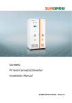
USER‘S MANUAL
BLITZ Laser 5 or 8 Watt
Copyright © by LaserAnimation GmbH. All rights reserved
LaserAnimation Sollinger GmbH
Crellestrasse. 19/20
D-10827 Berlin
P +49 (30) 780 963 00 Fax +49 (30) 780 963 25 Email: [email protected]
www.laseranimation.com
USER’S MANUAL BLITZ LASER
Version 2007-10-09
User’s Manual © by LaserAnimation Sollinger GmbH, 10827 Berlin, Deutschland.
Information in this document is subject to change without notice and does not represent a commitment on the part of the
manufacturer. The software described in this document is furnished under license agreement or nondisclosure agreement
and may be used or copied only in accordance with the terms of the agreement. It is against the law to copy the software
on any medium except as specifically allowed in the license or nondisclosure agreement. The purchaser may make one copy
of the software for backup purposes. No part of this manual may be reproduced or transmitted in any form or by any
means, electronic or mechanical, including photocopying, recording, or information storage and retrieval systems, for any
purpose other than for the purchaser‘ s personal use, without written permission.
Copyright © by LaserAnimation GmbH. All rights reserved
LaserAnimation Sollinger GmbH
Crellestrasse 19/20 - D-10827 Berlin
P +49 (30) 780 963 00 F +49 (30) 780 963 25
Email: [email protected]
www.laseranimation.com
-2-
USER’S MANUAL BLITZ LASER
Version 2007-10-09
Table Of Contents
1 Contents of Package .................................................................................................4
2 Safety Instructions .....................................................................................................5
2.1 General Hints.................................................................................................................................5
2.2 Hints For Laser Safety...................................................................................................................5
3 Getting Started ..........................................................................................................8
3.1 Connections/Displays ...................................................................................................................8
3.2 Installation ......................................................................................................................................9
3.2.1 Mechanical Setup...................................................................................................................9
3.2.2 Connecting the External Control and Display Elements .......................................... 11
3.3 Setup The Laser .......................................................................................................................... 13
3.4 Installation of Controlling Software......................................................................................... 14
3.4.1 Operating Modes ............................................................................................................... 15
3.4.2 Timer And Startup ............................................................................................................. 18
3.4.3 Beam Mode And Level....................................................................................................... 20
3.5 Key Switch ................................................................................................................................... 21
4 Hints For Maintenance ............................................................................................ 22
5 Malfunction............................................................................................................... 23
6 Pin Assignments ...................................................................................................... 24
6.1 Pin Assignment „Multifunction“ 15pin Dsub Connector .................................................. 24
6.2 Pin Assignment "Remote" Connector 7 pin XLR female .................................................. 25
7 Components ............................................................................................................. 26
7.1 Standard Components ............................................................................................................... 26
7.2 Optional Components ............................................................................................................... 26
8 Operation with UPS................................................................................................ 27
Technical Specifications ............................................................................................. 28
Copyright © by LaserAnimation GmbH. All rights reserved
LaserAnimation Sollinger GmbH
Crellestrasse 19/20 - D-10827 Berlin
P +49 (30) 780 963 00 F +49 (30) 780 963 25
Email: [email protected]
www.laseranimation.com
-3-
USER’S MANUAL BLITZ LASER
Version 2007-10-09
1 Contents of Package
Please make sure that all components were delivered correctly:
1 Remote cable
(adapter XLR 7 pin
plug to D-Sub 9 pin
female)
1 Mains cable
2 Mounting brackets
including 9 M4x6 hexgon socket screws and
9 spring washers, black
1 Set keys
(2 pcs.)
1 Shipping case
1 CD with PC Software „BLITZControl“
Optional
Remote control with
manual
Optional
Emergency shut-off
unit
If you discover damages to the device or the packing material due to improper transportation,
please inform the shipping company and return the device to the supplier in its original packing.
All necessary connecting cables are included, packed separately, please see the attached packing
list. If you discover that anything is missing, please contact your dealer.
Copyright © by LaserAnimation GmbH. All rights reserved
LaserAnimation Sollinger GmbH
Crellestrasse 19/20 - D-10827 Berlin
P +49 (30) 780 963 00 F +49 (30) 780 963 25
Email: [email protected]
www.laseranimation.com
-4-
USER’S MANUAL BLITZ LASER
Version 2007-10-09
2 Safety Instructions
2.1 General Hints
The BLITZ LASER has to be used according to this manual. LaserAnimation does not assume
liability for damages caused by non-observation of this manual.
The installation should be performed by specially trained personnel. Pay attention to the hints in
the chapter “3 Getting Started”.
Please note the local safety regulations!
The fans of BLITZ LASER should not be covered and possible pollutions should be removed in
order to circulate enough air for cooling during operation.
Before starting any maintenance or cleaning cut off the power supply!
In case of malfunctions please send the device to your dealer for inspection and repair in its original packing.
Attention! Warranty is void if the device is misused, damaged, modified in any way,
or for unauthorized repairs or parts.
2.2 Hints For Laser Safety
The internal laser head is a 5 or 8W DPSS high power laser class 4 according to EN 60825-1:
According to DIN EN 60825-1:2001 the following warning labels are placed on the BLITZ LASER:
Laser radiation is emitted
from this output!
Copyright © by LaserAnimation GmbH. All rights reserved
LaserAnimation Sollinger GmbH
Crellestrasse 19/20 - D-10827 Berlin
P +49 (30) 780 963 00 F +49 (30) 780 963 25
Email: [email protected]
www.laseranimation.com
-5-
USER’S MANUAL BLITZ LASER
Version 2007-10-09
Danger! High Voltage!
Disconnect mains before opening!
VISIBLE AND INVISIBLE LASER RADIATION
AVOID EYE OR SKIN EXPOSURE
TO DIRECT OR SCATTERED RADIATION
CLASS IV LASER PRODUCT
EN 60825-1:1994
Warnings
Read this manual carefully before operating the laser in order to prevent injuries to humans and damages to devices due to improper operation.
Be very cautious and careful when operating the BLITZ LASER (laser class
4). Observe the warning labels on the device.
Never operate the device in a hazardous environment.
Avoid any reflections back into the laser to prevent damages to the laser and
the NLO.
The power supply of the laser and the laser head do not contain any parts
that can be serviced, adjusted or replaced by the user. Therefore, never open
the rear cover. In case of problems, please contact our technical support.
In case the device has to be opened, this should only be done by trained personnel. Always wear protective goggles if the device is opened during operation.
The most light sensitive organ of the human is the eye. A laser beam is coherent, monochromatic light with very high energy. A laser beam retains its
intensity even over very long distances. If a laser beam hits the human eye
under conditions exceeding the limits of the international laser safety standard (DIN EN 60825-1:2001-11), this can lead to irreparable damages to the
cornea, the conjunctiva, the eye lens and the retina.
Therefore, never look directly into the laser beam and do not place any
Copyright © by LaserAnimation GmbH. All rights reserved
LaserAnimation Sollinger GmbH
Crellestrasse 19/20 - D-10827 Berlin
P +49 (30) 780 963 00 F +49 (30) 780 963 25
Email: [email protected]
www.laseranimation.com
-6-
USER’S MANUAL BLITZ LASER
Version 2007-10-09
objects into the laser beam because even diffusely reflected radiation can
cause eye damages.
Take precautions and counter measures to prevent a direct or reflected
beam.
The high energy density of the laser beam causes painful burns when it hits
human skin. The beam will also burn holes into textiles. Therefore never
reach into the laser beam and do not let other parts of the body get in the
way of the laser beam.
If the laser beam hits easily flammable materials such as paper, these will
ignite and a fire can develop very quickly. Therefore make sure that no flammable material is in the way of the beam before activating the laser.
Make sure that no unauthorized persons have access to your laser system.
Observe the following safety precautions when operating the laser system in
front of an audience:
Mark an area of about 3 to 4 m around the laser system as off limits to
the audience.
Only test the laser system as long as no audience is present.
Set the laser to the lowest visible beam level (laser class 1) while adjusting optical components within the system such as mirrors, beam splitters.
Only clean optical components and the beam emission window while the
laser is turned off.
Before turning the system on regularly check if the settings of the laser
are correct to make sure that no unauthorized person has made any
changes to the laser system.
Never let the laser run unattended.
The user of the device has the full responsibility for marking safety areas,
setting up warning notices and instructing other persons using the device
about the safety regulations.
Copyright © by LaserAnimation GmbH. All rights reserved
LaserAnimation Sollinger GmbH
Crellestrasse 19/20 - D-10827 Berlin
P +49 (30) 780 963 00 F +49 (30) 780 963 25
Email: [email protected]
www.laseranimation.com
-7-
USER’S MANUAL BLITZ LASER
Version 2007-10-09
3 Getting Started
3.1 Connections/Displays
(1) Power connector (IEC), fused
Input voltage 90-132VAC, 180-264VAC, 47-63Hz, auto switch
(2) Key switch for laser on/off
(3) Laser emission display
(4) 15 pin D-sub connector for modulation signal, interlock loop, external key switch,
external laser emission display, serial interface
modulation signal (differential input): 0 — 5V
(5) XLR 7pin for connecting the remote control
Copyright © by LaserAnimation GmbH. All rights reserved
LaserAnimation Sollinger GmbH
Crellestrasse 19/20 - D-10827 Berlin
P +49 (30) 780 963 00 F +49 (30) 780 963 25
Email: [email protected]
www.laseranimation.com
-8-
USER’S MANUAL BLITZ LASER
Version 2007-10-09
3.2 Installation
The BLITZ LASER is intended to be installed in a laser system, therefore it has no power
switch.
A laser system usually has the following control and display elements which are accessible to the
user:
1)
laser emission display
2)
key switch
3)
emergency-off button
4)
serial interface for controlling and monitoring the laser
5)
modulation signal (may be internal and not accessible to the user)
6)
connector for remote control unit
7)
power switch with signal lamp
The 15 pin multi-function connector can be used to connect the control and display elements 1)
to 5).
3.2.1 Mechanical Setup
Install the BLITZ LASER on your optical bench. Two mounting brackets for simple installation
on an optical bench are included, attach the brackets e.g. as follows:
brackets
Copyright © by LaserAnimation GmbH. All rights reserved
LaserAnimation Sollinger GmbH
Crellestrasse 19/20 - D-10827 Berlin
P +49 (30) 780 963 00 F +49 (30) 780 963 25
Email: [email protected]
www.laseranimation.com
-9-
USER’S MANUAL BLITZ LASER
Version 2007-10-09
Dimensions of the bracket (mm):
11
14.5
30
4.5
31
91
151
211
19
30
6.5
50
51
193
242
The holes for the brackets are located on the front and the rear side of the device.
Distances (mm):
20
65
8 x M4
153
93
33
213
Copyright © by LaserAnimation GmbH. All rights reserved
LaserAnimation Sollinger GmbH
Crellestrasse 19/20 - D-10827 Berlin
P +49 (30) 780 963 00 F +49 (30) 780 963 25
Email: [email protected]
www.laseranimation.com
- 10 -
USER’S MANUAL BLITZ LASER
Version 2007-10-09
Make sure that the laser module is fixed immovably and that the air intake and outlet openings
are not obstructed.
Place an adequately dimensioned beam block in front of the beam exit which limits reflections
to a minimum.
3.2.2 Connecting the External Control and Display Elements
1. Interlock Loop/Emergency Shut-Off Unit:
For operation the interlock loop has to be closed! In the included 15pin D-Sub connector, the interlock loop is closed by a soldered connection.
In place of the soldered connection please connect an emergency-off button, which opens
the interlock loop when it is activated.
At least one emergency-off button always has to be connected. Place the button where it
can be reached as quickly as possible in case of an emergency. Make sure that the laser is
turned off when the button is pushed by testing it each time the laser is activated.
2. Modulation Input:
Usually the BLITZ LASER is in the modulation mode, i.e. the laser power is controlled by
the voltage at the modulation input. For this a positive voltage from 0V to a maximum of
+5V DC has to be applied between the inputs Green+ and Green-.
3. Optional Remote Control Unit:
If you have LaserAnimation’s BLITZ remote control unit, connect this to the “Remote” connector of the BLITZ LASER:
7pin XLR
Connector
BLITZ Remote
Control Unit
Copyright © by LaserAnimation GmbH. All rights reserved
LaserAnimation Sollinger GmbH
Crellestrasse 19/20 - D-10827 Berlin
P +49 (30) 780 963 00 F +49 (30) 780 963 25
Email: [email protected]
www.laseranimation.com
- 11 -
USER’S MANUAL BLITZ LASER
Version 2007-10-09
4. Serial Interface using the “Remote” Connector:
The BLITZ LASER can be controlled by a PC using the included software “BlitzControl” or
by a Lasergraph DSP. Therefore connect the included adapter cable (7-pin XLR plug/9-pin
D-Sub female connector) to the “Remote” connector.
adapter
cable
5. Optional Laser Emission Display:
You can connect a standard LED without resistor. This will light up when a laser beam can
be emitted.
6. Optional Key Switch:
This switch is connected parallel to the key switch on the device. If you use an external key
switch, the key switch on the device should be open, i.e. in the vertical position = Laser Off.
7. Optional Serial Interface:
Please note that this interface is deactivated as soon as the remote control unit or the included adapter cable is connected to the “Remote” connector.
Copyright © by LaserAnimation GmbH. All rights reserved
LaserAnimation Sollinger GmbH
Crellestrasse 19/20 - D-10827 Berlin
P +49 (30) 780 963 00 F +49 (30) 780 963 25
Email: [email protected]
www.laseranimation.com
- 12 -
USER’S MANUAL BLITZ LASER
Version 2007-10-09
3.3 Setup The Laser
1. Mains Connection
Make sure that the key switch is in the vertical position = Laser Off (rear panel or external
key switch).
The BLITZ LASER can be operated with mains voltages 115V/60Hz or 230V/50Hz; the appropriate mains voltage setting is selected automatically.
Connect the included power cable to the power connector of the device and connect the
BLITZ LASER to the mains supply.
As soon as the mains voltage is applied, the BLITZ LASER will be initialized. The temperature of the non linear optics is brought to its target value and kept there. The temperature
of the laser diode is monitored so that the emission can be started without delay.
This can take several minutes, depending on the ambient temperatures.
The serial interface is activated.
2. Make sure that the connected modulation signal is less than 0.5V DC in the beginning.
3. Turn the laser on by turning the key switch to the right — horizontal position (vertical key
position means laser off)
Note:
If the remote control is connected, both key switches have to be turned to the right.
The start-up mode set on delivery is “RUN 100%”, i.e. when a modulation signal is present,
the maximum laser power will be emitted when the interlock loop is closed and the key
switch is switched to the ON position (closed).
The emission will be indicated by the "Laser" LED.
The device can only operate in the RUN, TEST or STANDBY modes when the target temperatures have been reached.
When the laser is in the RUN state, increase the modulation voltage. A laser beam should
now be visible.
Never look into the beam or the beam exit either directly or through reflecting objects.
We urgently recommend to use laser protective classes during setup the
laser.
Copyright © by LaserAnimation GmbH. All rights reserved
LaserAnimation Sollinger GmbH
Crellestrasse 19/20 - D-10827 Berlin
P +49 (30) 780 963 00 F +49 (30) 780 963 25
Email: [email protected]
www.laseranimation.com
- 13 -
USER’S MANUAL BLITZ LASER
Version 2007-10-09
3.4 Installation of Controlling Software
The BLITZ LASER is comfortably operated by the included software „BlitzControl “ via PC or
by the optional BLITZ remote control.
For the operation with the BLITZ remote control a separate manual is available, therefore the
controlling by a PC will be described in the following.
Insert the included CD in the CD-Rom drive of your PC and start the installation by selection
of the program file “BlitzControl.exe“. Attend the orders on the screen.
Start the program by double clicking to the program icon on your desktop. After starting the
program the current state of the device will be displayed in the “Status” window if a connected
device is recognized:
Note:
The program recognizes the „COM-Port“ (serial interface) immediately.
If not check the connection between your BLITZ LASER and your PC and assign the correct
COM-Port in the pull-down menu:
Copyright © by LaserAnimation GmbH. All rights reserved
LaserAnimation Sollinger GmbH
Crellestrasse 19/20 - D-10827 Berlin
P +49 (30) 780 963 00 F +49 (30) 780 963 25
Email: [email protected]
www.laseranimation.com
- 14 -
USER’S MANUAL BLITZ LASER
Version 2007-10-09
3.4.1 Operating Modes
The BLITZ LASER has four operating modes which the user can set:
“OFF”
The laser diode is turned off and its temperature is no longer controlled.
Therefore a certain delay may occur when switching to the RUN-, TEST- or
STANDBY mode because the optimal temperature has to be reached first.
“STANDBY”
The laser diode is tuned off but is kept at its optimal temperature. The laser
can be switched to the RUN or TEST mode without delay.
“RUN”
The laser diode is kept at its optimal temperature and is active.
“TEST”
This is similar to the RUN mode with the exception that the power level is set
constantly to 10% of the maximum possible power and cannot be changed (and
not modulated).
Note:
If for instance the laser is switched from the OFF- to the STANDBY state and therefore the
correct operating temperatures have to be reached, the laser is in an intermediate state
(ADJUSTING). The display of the temperature that has not reached its target value is flashing.
Copyright © by LaserAnimation GmbH. All rights reserved
LaserAnimation Sollinger GmbH
Crellestrasse 19/20 - D-10827 Berlin
P +49 (30) 780 963 00 F +49 (30) 780 963 25
Email: [email protected]
www.laseranimation.com
- 15 -
USER’S MANUAL BLITZ LASER
Version 2007-10-09
“Laserstatus” displays the current states:
•
•
•
•
•
•
•
•
•
“Power”
“Current Diode”
Power of the laser beam in Watts
Electric current through the laser diode in Ampere
(peak value measurement)
“Temp. Diode”
Temperature of the diode
“Heat Sink”
Temperature of the heat sink
“NLO”
Temperature of the NLO (non linear optics)
“Power Diode”
Cooling capacity or heating power of the temperature control for the
diode as percentage (peak value measurement)
“Cooling Power NLO” Cooling capacity or heating power of the temperature control for the
NLO as percentage
“Key”
State of the key switch
“Interlock”
State of Interlock
“Operation Hours”:
• “General”
• “Standby”
•
•
“Laser”
“Power”
General operating hours (when the device is turned on).
Operating hours during which the device is in any state other than
OFF.
Operating hours during which the laser diode is under current.
Operating hours during which the laser diode is operated with high.
Copyright © by LaserAnimation GmbH. All rights reserved
LaserAnimation Sollinger GmbH
Crellestrasse 19/20 - D-10827 Berlin
P +49 (30) 780 963 00 F +49 (30) 780 963 25
Email: [email protected]
www.laseranimation.com
- 16 -
USER’S MANUAL BLITZ LASER
Version 2007-10-09
The system contains a real time clock with a back up battery which provides time and date. The
clock can be set in the “Blitztimer” window:
The three lower lines (green colored) always display the laser state (line 1), the beam mode
(line 2) and if so information e.g. “Timer” setting or error messages (line 3).
Malfunctions or error messages will always be displayed red colored.
Copyright © by LaserAnimation GmbH. All rights reserved
LaserAnimation Sollinger GmbH
Crellestrasse 19/20 - D-10827 Berlin
P +49 (30) 780 963 00 F +49 (30) 780 963 25
Email: [email protected]
www.laseranimation.com
- 17 -
USER’S MANUAL BLITZ LASER
Version 2007-10-09
3.4.2 Timer And Startup
A timer is necessary if the laser is to change to another state at a specific time (either daily or
on a defined date) (e.g. from STANDBY MODULATED to RUN 100% FIXED).
Up to six of these timers can be active simultaneously:
If a timer was triggered, the message line will display a corresponding message. The message will
only be deleted when another timer has been triggered or the operating mode is changed manually.
Copyright © by LaserAnimation GmbH. All rights reserved
LaserAnimation Sollinger GmbH
Crellestrasse 19/20 - D-10827 Berlin
P +49 (30) 780 963 00 F +49 (30) 780 963 25
Email: [email protected]
www.laseranimation.com
- 18 -
USER’S MANUAL BLITZ LASER
Version 2007-10-09
The state which the Accurate BLITZ is to take on immediately after it is turned on can also be
set by editing “Startup”:
For safety reasons the laser can only be started in MODULATED mode.
If the device is to switch into the RUN- or TEST mode immediately when it is turned on, it is
necessary that the key is in the "On" position before the device is turned on.
The timer settings will not be deleted when the device is turned off.
Therefore always deactivate timers after using the device to avoid problems for another user who does not know about the timers.
As a precaution look at the timer settings each time you turn the Accurate Blitz on.
Treat the FIXED mode with caution. Only use it when you are sure that
the beam cannot hit people.
Copyright © by LaserAnimation GmbH. All rights reserved
LaserAnimation Sollinger GmbH
Crellestrasse 19/20 - D-10827 Berlin
P +49 (30) 780 963 00 F +49 (30) 780 963 25
Email: [email protected]
www.laseranimation.com
- 19 -
USER’S MANUAL BLITZ LASER
Version 2007-10-09
3.4.3 Beam Mode And Level
The laser beam can be either MODULATED or FIXED in the RUN mode.
MODULATED: The laser beam can be modulated between 0 and 100% of the maximum power
in the “RUN” mode. The power is set with the slider:
FIXED:
A fixed beam is generated with the power set, independent of the modulation
input or the scan fail and beam stop settings.
Use the FIXED MODE with caution because a static beam is possible
which can cause severe injuries or fires.
Note:
The program components „Projection“, „Scanfail“ and „Beam Stop“ are not available with laser
BLITZ LASER, because the device is not equipped with a projection unit.
Copyright © by LaserAnimation GmbH. All rights reserved
LaserAnimation Sollinger GmbH
Crellestrasse 19/20 - D-10827 Berlin
P +49 (30) 780 963 00 F +49 (30) 780 963 25
Email: [email protected]
www.laseranimation.com
- 20 -
USER’S MANUAL BLITZ LASER
Version 2007-10-09
3.5 Key Switch
The effect on the system of turning the key switch will be illustrated using several examples.
In general the following applies: if the key switch is in the OFF position, no RUN or TEST state
is possible.
Example 1:
The key switch is in the OFF position when the device is turned on. However, you have determined in the STARTUP that the laser is to switch to the RUN state immediately after the device
is turned on. Since the key switch is turned to OFF, the laser can only reach the STANDBY
state. If the key switch is turned to ON now, the laser will immediately switch to the RUN state
unless you have selected another state beforehand with the remote control or by activating a
timer.
Example 2:
The key switch is turned to the OFF position while the device is running in the STANDBY state.
If a timer is activated now which demands the RUN state, this is impossible because of the key
switch position. If the key switch is turned to ON now, the laser will immediately reach the
state demanded by the timer activated most recently unless you have selected another state
beforehand with the remote control.
Example 3:
The key switch is turned to the OFF position while the device is running in the STANDBY state.
If the RUN state is now demanded via remote control, this is impossible because of the key
switch position. If the key switch is turned to ON now, the laser will immediately reach the
state demanded by the remote control unless another state was selected by an activated timer
beforehand.
Example 4:
The key switch is turned to the OFF position while the device is running in the RUN state. This
will switch the laser to the STANDBY state immediately. If the key switch is turned to the ON
position now, the laser will be switched back to the RUN state immediately, unless you have
selected another state beforehand with the remote control or by activating a timer.
Example 5:
The device is running in the RUN state. Due to an error or by interruption of the interlock
loop (e.g. activation of emergency off) the device is turned to the OFF or STANDBY state immediately. You can turn the laser back to the RUN state now by eliminating the error (e.g. deactivating emergency off) and briefly turning the key switch to OFF and then back to the ON
position.
Copyright © by LaserAnimation GmbH. All rights reserved
LaserAnimation Sollinger GmbH
Crellestrasse 19/20 - D-10827 Berlin
P +49 (30) 780 963 00 F +49 (30) 780 963 25
Email: [email protected]
www.laseranimation.com
- 21 -
USER’S MANUAL BLITZ LASER
Version 2007-10-09
4 Hints For Maintenance
Do not use the BLITZ LASER in very damp (not in the rain or in environments with more than
70% humidity) and polluted environments.
The housing of the device can be cleaned with a soft fluff-less cloth and e.g. acetone.
Check the fans on the side of the BLITZ LASER regularly. Depending on the operating environment large amounts of dirt can accumulate on the fans after a short time. This definitely has to
be removed to guarantee trouble free operation. This can best be done with a vacuum cleaner
or a brush. You can also use an oil-free compressed air cleaner.
Turn the laser off and disconnect the device from the mains before
cleaning!
For safe transportation please use the included shipping case or a flight case.
Copyright © by LaserAnimation GmbH. All rights reserved
LaserAnimation Sollinger GmbH
Crellestrasse 19/20 - D-10827 Berlin
P +49 (30) 780 963 00 F +49 (30) 780 963 25
Email: [email protected]
www.laseranimation.com
- 22 -
USER’S MANUAL BLITZ LASER
Version 2007-10-09
5 Malfunction
•
Check the mains connection!
In case of malfunction please check the mains connection and mains cable first. If necessary
change the mains cable.
•
Check the fuse of the device!
Further the internal device fuse can be defect. It is easy to replace the fuse. For this purpose
remove the fuse holder underneath the mains connector using a screw driver for slotted
screws. You will then see two fuses. The one located at the front is a spare.
fuse holder
Correct Replacement Fuses:
Mains Voltage
90V-132V/47-63Hz
180V-264V/47-63Hz
•
Fuse
5A slow-acting
4A slow-acting
Laser Power Too Low?
First check the power in the "fixed" beam mode. If the laser output power is only too low in
the "modulated" mode the reason may be that the input signal level is too high (e.g. peaks).
Since the input signal level is not limited internally this may have the result that the current
in the laser diode is too high. The software registers this raised current and reduces it by
adjusting internal values. This way the laser output power may be too low even though the
input signal level is normal.
The values can be reset by restarting the laser or by selecting the "OFF"-mode in the control software or with the "BLITZ" remote control.
In case of other malfunctions please send the BLITZ LASER to your dealer for
inspection and repair in its original packing.
Copyright © by LaserAnimation GmbH. All rights reserved
LaserAnimation Sollinger GmbH
Crellestrasse 19/20 - D-10827 Berlin
P +49 (30) 780 963 00 F +49 (30) 780 963 25
Email: [email protected]
www.laseranimation.com
- 23 -
USER’S MANUAL BLITZ LASER
Version 2007-10-09
6 Pin Assignments
6.1 Pin Assignment „Multifunction“ 15pin Dsub Connector
Pin
No.
1
2
3
4
5
6
7
8
9
10
11
12
13
14
15
Signal
LED anode
Interlock A
Key
n.c.
Green+
reserved
TxD
GND
LED cathode
Interlock B
Key
n.c.
Greenreserved
RxD
Level
Meaning
optional emission display
interlock loop
optional key switch
0V ... +5V
against green(differential)
modulation signal (analog)
0% of the adjusted laser power
to
5V : 100% of the adjusted laser power
RS 232
serial interface PIN 2
serial interface PIN 5
emission display
0V :
interlock loop
optional key switch
return lead for green+ signal
RS 232
serial interface PIN 3
1
LED optional emission display
9
2
INTERLOCK
10
3
optional key switch
11
4 NC
12 NC
5
Green+
13
Green-
modulation signal
e.g. PC or DSP
D9 PIN
6
14
7
TxD
2
15
RxD
3
8
GND
5
optional
serial
interface
Copyright © by LaserAnimation GmbH. All rights reserved
LaserAnimation Sollinger GmbH
Crellestrasse 19/20 - D-10827 Berlin
P +49 (30) 780 963 00 F +49 (30) 780 963 25
Email: [email protected]
www.laseranimation.com
- 24 -
USER’S MANUAL BLITZ LASER
Version 2007-10-09
6.2 Pin Assignment "Remote" Connector 7 pin XLR female
Pin No.
1
2
3
4
5
6
7
Signal
Interlock
Interlock
TxD
Remote Key
RxD
VCC
GND
Meaning
When both interlock lines are connected: INTERLOCK ON
Data from laser (RS232-level)
If connected to +24V: KEY ON (key switch on remote control)
Data to laser (RS232-level)
+24V (power supply for remote control) max. 250mA
Ground
Attention!
By plugging of the remote cable or the remote control the serial interface of the multifunction connector will be deactivated!
Remote Cable (serial)
XLR 7 pin
male
Interlock
TxD
Key
10k
RxD
GND
remote
cable
Dsub 9 pin
female
Copyright © by LaserAnimation GmbH. All rights reserved
LaserAnimation Sollinger GmbH
Crellestrasse 19/20 - D-10827 Berlin
P +49 (30) 780 963 00 F +49 (30) 780 963 25
Email: [email protected]
www.laseranimation.com
- 25 -
USER’S MANUAL BLITZ LASER
Version 2007-10-09
7 Components
7.1 Standard Components
•
Highly reliable diode pumped thin-disc laser JenLas™ D2- with built in high-grade beam
expander/collimator (3x):
Laser class according to EN 60835-1
Laser output power
Wave length
Feature
Beam parameters
Expected lifetime
Ambient temperature
4
5 or 8 W cw operation
green = 532nm
directly modulated
Analog modulation of the laser power up to approx.
100kHz by directly modulating the diode current,
suitable for softblanking and TV-like raster images
diameter: 3mm
divergence: approx. 1mrad
more than 10,000 hours
+10 to +50°C (50 to 122°F)
•
Processor controlled compact power supply with high efficiency for the laser head
(approx. 160W power consumption in normal operation).
It guarantees permanent monitoring of all important functions, immediate shut-down in case
of malfunction.
•
An effective cooling system consisting of 3 fans (low noise “Papst” fans) and 2 thermoelectric coolers for laser diode and NLO (non linear optics).
The temperature of both components is kept constant (processor-controlled regulation).
This makes operation of the Accurate BLITZ Stage in ambient temperatures from +10 to
+50°C (50 to 122°F) possible.
The target values of the temperatures depend on the individual laser head. The optimal
temperatures at which the laser supplies the highest power are set as constants during production.
The heating phase takes less than 2 minutes after the device is turned on.
7.2 Optional Components
•
Versatile “BLITZ Remote Control” with clearly arranged display, key switch and emergencyoff button for comfortable controlling of operating data. (Manual included.)
•
Separate emergency shut-off unit
Copyright © by LaserAnimation GmbH. All rights reserved
LaserAnimation Sollinger GmbH
Crellestrasse 19/20 - D-10827 Berlin
P +49 (30) 780 963 00 F +49 (30) 780 963 25
Email: [email protected]
www.laseranimation.com
- 26 -
USER’S MANUAL BLITZ LASER
Version 2007-10-09
8 Operation with UPS
The mains supply at events may be "contaminated" (e.g. voltage peaks) due to the large number
of connected devices (e.g. dimmers). This can cause problems in the operation of the BLITZ
LASER.
To ensure safe operation of the laser in spite of this it is highly recommended to run the laser
with the aid of a UPS (Uninterrupted Power Supply). This is set up between the mains supply
and the mains connector of the laser and ensures a clean AC voltage.
A UPS can be obtained from any supplier for electric appliances or computers. You need a "Line
Interactive" UPS with an output power of up to 500W.
Copyright © by LaserAnimation GmbH. All rights reserved
LaserAnimation Sollinger GmbH
Crellestrasse 19/20 - D-10827 Berlin
P +49 (30) 780 963 00 F +49 (30) 780 963 25
Email: [email protected]
www.laseranimation.com
- 27 -
USER’S MANUAL BLITZ LASER
Version 2007-10-09
Technical Specifications
Physical
252mm /9.9in.
Size (L x W x H)
Weight
176mm / 6.9in.
176mm
133mm / 5.2in.
75mm / 2.95in.
244mm / 9.6in.
252 x 244 x 176mm (9.9 x 9.6 x 6.9in.)
approx. 11.5kg (25.35lb)
Construction
Powder-coated steel plate, black
Operation
Installation on an optical bench
Laser
Class
Type
4 (according to EN 60825-1)
Thin-disk laser, diode-pumped - DPSS
5 or 8 W cw operation
with built-in power measurement
532nm
5W
8W
maximum 6W
maximum 10W
maximum 10mW
maximum 20mW
3mm
1mrad
Adjustable, allows expansion of beam to 3mm
(Galilei principle)
Output power
Wavelength
Pλ 532nm
Pλ 1064nm
Beam Diameter
Beam Divergence
Collimator
Power Supply
Type
Electrical power consumption
Processor controlled
Approx. 160W (normal operation)
Copyright © by LaserAnimation GmbH. All rights reserved
LaserAnimation Sollinger GmbH
Crellestrasse 19/20 - D-10827 Berlin
P +49 (30) 780 963 00 F +49 (30) 780 963 25
Email: [email protected]
www.laseranimation.com
- 28 -
USER’S MANUAL BLITZ LASER
Version 2007-10-09
Cooling System
3 low noise temperature controlled Papst fans
2 thermoelectric cooler for laser diode and NLO (non linear optics)
Thermal
Maximum ambient temperature
Minimum ambient temperature
Recommended ambient temperature
+50°C (122°F)
+10°C (50°F)
+20 to +25°C (68 to 77°F)
Connections / Display
Standard fused IEC power connector with On/Off switch
Input voltage 90-132VAC, 180-264VAC, 47-63Hz, auto switch
Key switch for laser On/Off
LED for laser emission
15-pin D-sub connector for modulation signal 0 — 5V (differential input) with interlock
loop
XLR 7-pin for remote control
Included Items
1 IEC power cable with Schuko (Euro) plug (2m / 79in.)
2 Keys for key switch
1 CD with software “BlitzControl”
1 Remote cable with 7-pin XLR plug and 9-pin Sub-D plug (1m / 40in.)
2 Mounting brackets
9 M4x6 cylinder socket head screws, black
9 Spring washers
1 Shipping case
Accessories
BLITZ remote control
Separate emergency shut-off unit
Warranty (according to the general conditions of business)
12 month following delivery or approval
Note: Technical specifications subject to change without notice!
Copyright © by LaserAnimation GmbH. All rights reserved
LaserAnimation Sollinger GmbH
Crellestrasse 19/20 - D-10827 Berlin
P +49 (30) 780 963 00 F +49 (30) 780 963 25
Email: [email protected]
www.laseranimation.com
- 29 -