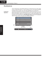
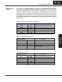
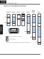
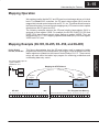
1
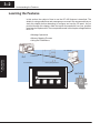
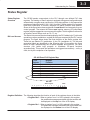
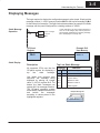
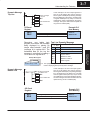
Understanding the
Features
13
In This Chapter. . . .
— Learning the Features
— Status Register
— Messages
— Displaying Messages
— Pushbuttons
— Memory Mapping Process
— DirectLOGIC User Memory Overview
— Mapping Operation
— Mapping Example (DL105/DL205/D3–350/DL405)
— Mapping Example (D3–340)
3–2
Understanding the Features
Learning the Features
In this section, the subject of how to use the OP–420 features is described. The
details for using pushbuttons and messages are covered. We recommend that you
study this chapter before attempting to configure and use the OP-panel. As you
proceed through this chapter, relate the topics discussed with how your operator
panel may be implemented. The concepts discussed in this chapter are applicable to
all PLCs.
SMessage Operations
SMemory Mapping Process
SUsing the Pushbuttons
OP–WINEDIT
Understanding
the Features
PLC
Pushbuttons...
Process Data.....
Memory Requirements...
MACHINE
3–3
Understanding the Features
Status Register
The OP400 panels communicate to the PLC through user defined PLC data
registers. The starting or “Base” register is assigned during panel configuration and
automatically occupies seven consecutive 16-bit data registers. In this manual the
registers are identified as M+0, M+1, M+2, thru M+6. Status register M+6 contains
bit-of-word information to monitor individual OP-panel functions and features.
Shown in the figure below, base register M+6 must have bit level access by the user
control program. That means the Status word register memory (OP-panel Base
register) must be mapped to a user memory bit register. This bit register is referred to
as Internal Control Relays such as C0, C1, etc.
Bit Level Access
The Status bits are monitored and manipulated by the PLC ladder logic. For discrete
operations such as pushbuttons, register M+6 bits are accessed by the PLC control
program. The figure below shows the fixed definition of the Status register bits.
These bits are labeled F1 (pushbutton 1) thru F4 (pushbutton 4). The bits and
associated labels are described on the following page. First examine the figure
below to begin understanding the OP-panel registers and functions. You must
structure your ladder logic program to coordinate OP-panel functions
asynchronously. This means the operations are triggered successively – not by a
clock, but by the completion of an operation.
PLC
Register
M+0
M+1
M+2
M+3
M+4
M+5
M+6
Register
Function
Top line message selection
Bottom line message selection
Top line data
Top line data 2 (for long BCD and floating point numbers)
Bottom line data
Bottom line data 2 (for long BCD and floating point numbers)
Status register
OP–420
Status Register
M+6
Register Definition The following describes the function of each of the registers shown in the table.
S Register M+0 – When a number from 1 to 160 is placed in this register,
the predifined message associated with that number will
be displayed on the top line of the LCD display.
S Register M+1 – When a number from 1 to 160 is placed in this register,
the predifined message associated with that number will
be displayed on the bottom line of the LCD display.
Understanding
the Features
OP–420 Panel PLC Register Map
Entering Programs
Status Register
Overview
3–4
Understanding the Features
S Register M+2 – This contains numeric data associated with the top line
display (this is described in more detail later).
S Register M+3 – This is used for long BCD and floating point data only.
S Register M+4 – This contains numeric data associated with the bottom
line display (this is described in more detail later).
S Register M+5 – This is used for long BCD and floating point data only.
S Register M+6 – This is the status register. Bits 0 thru 3
monitor the status of pushbuttons F1 thru F4. These bits
are set to 1 when the pushbuttons are active.
Messages
Understanding
the Features
Displaying
Messages on the
LCD Screen
Through the OP–WINEDIT software, up to 160 predefined messages can be
entered and stored in the OP–420. These messages are 20 characters long and can
include a field for the display of numeric data.
Any predefined message can be displayed on either the top or bottom line. The
messages entered during configuration are numbered 1 thru 160. To display a
particular predefined message on the display, simply place that message’s number
in the message selection register.
For example, let’s assume that we have
defined message #16 as “Mary had a
little” and message #22 as “white fleeced
lamb”. If we wanted to put these two lines
on the top and bottom lines respectively,
we would simply need to put the number
16 in register M+0 and 22 in register M+1.
If any number other than 1 thru 160 is
placed in a message selection register,
the associated line will not change.
Example Message:
Mary had a little
white fleeced lamb
To display message #16 here,
place 16 in register M+0.
To display message #22 here,
place 22 in register M+1.
There are two types of messages which may be displayed on this panel, Static and
Dynamic messages.
Static Messages
Static messages are text displays which
have no embedded data. The static
messages may be displayed when an
event or condition becomes true. You
enter
the
messages
during
configuration.
Dynamic Messages Dynamic messages are text messages
which include embedded data. These
messages are used to present the
operator with important PLC data. This
data is information which helps the
operator closely monitor and control the
machine or process.
Example Static Message:
SYSTEM RUNNING
Example Dynamic Message:
Zone1 Temp.: ^^^^
Data Value update from PLC register
3–5
Understanding the Features
Displaying Messages
The logic required to display the configured message is quite simple. Simply put the
message number (1–160) in memory location M+0 for the top line message or M+1
for the bottom line message. The figure below demonstrates an example of a Static
message with the panel configured for a starting address of V2000.
Static Message
Operation
X3
ON
Selects message#
for Top line
OUT
V2000
M+0
In this example, if the PLC’s input signal X3 is
ON, the 16 bit integer (K3) value is placed in
Word register V2000 (M+0), selecting message
#3 to be displayed on the top line.
OP-Panel
Register
M+0
Example PLC
User Memory
V2000 = 3
Message # request
ËËËËË
ËËËËË
ËËËËË
Top Line Static Message
Function
All supported CPUs use the first Register
Value
Description
OP-panel register for displaying a
top
line
static
message.
Your ladder logic program must
sequence the message being
displayed by placing an integer
value (1–160) in register M+0. For
bottom line static messages use
register M+1 for message selection.
The OP-panel operating system
automatically updates the latest top
and
bottom
line
messages
according to values placed in the
highlighted registers.
M+0
M+1
M+2
M+3
M+4
M+5
M+6
3
Top line message selection
Bottom line message selection
Top line data
Top line data 2
Bottom line data
Bottom line data 2
Status register
Example Message #3
System Running
Understanding
the Features
Static Display
Entering Programs
LD
K3
3–6
Understanding the Features
Dynamic Message
Operation
You may program message numbers 1–160 to be used as dynamic messages. One
numeric field per line is allowed. Dynamic messages may be displayed on either the
top or bottom display lines. The maximum number of digits which may be displayed
is five if binary data format is used, four if BCD is used, and eight if BCD double is
used. The figure below demonstrates the OP–WINEDIT screens for programming a
dynamic message.
Enter the message text and place the caret (^) symbol(s) depending on the number
of digits you would like to display. The value range which may be displayed is
0–65,535 integer, 0–9999 BCD or 0–99999999 BCDD. Choose binary, BCD, or BCD
double format and fixed point decimal placement.
For dynamic messages which require fixed decimal point placement within the
value, you must use the OP–WINEDIT to perform parameter placement type. For
fixed position decimal points you must enter the decimal directly into the message
text, such as Zone1 Temp = ^^.^^.
Understanding
the Features
For example, let’s say message #36 is “#
widgets sold: ^^^^”. Let’s also say that
465 widgets have been sold today. To
display the current number of widgets
sold on the bottom line of the display, you
would place 36 in register M+1 and 465 in
register M+4. The bottom line would then
display: “# widgets sold: 465”.
Examples of dynamic messages. Notice
the caret (^) symbols, which is where
data will be when the message is
displayed.
Example Message #36:
# widgets sold: 465
Place 36 in register M+1;
message is “# widgets sold: ^^^^”.
To display this, 465 must
be in register M+4.
3–7
Understanding the Features
Dynamic Message
Top Line
In this example, if the PLC’s input signal X4 is
ON, the 16 bit integer (K5) value is placed in
Word register V2000 (M+0) selecting message
#5 to be displayed on the top line. The data value
in register V3000 (let’s say 1100) is moved into
V2002 (M+2), which is embedded in the top line
message. The top line data value will update as
long as X4 is enabled (ON).
X4
ON
LD
K5
Selects message#
for Top line
OUT
V2000
M+0
LD
V3000
Loads variable data
OUT
V2002
M+2
OP-Panel
Register
Example PLC
User Memory
V2000 =5
Message # requested
Top line message data
V2002 =1100
ËËËËË
ËËËËË
M+4
M+5
M+6
Example Message #5
Zone1 Temp. +1100
Dynamic Message
Bottom Line
LD
K7
Selects message#
for Bottom line
OUT
V2001
M+1
LD
V3001
Loads variable data
OUT
V2004
M+4
OP-Panel
Register
M+1
M+4
Status register
The highlighted registers M+0 and M+2 in this figure
result in displaying this top-line dynamic message.
X5
ON
Bottom line data
Bottom line data 2
In this example, if the PLC’s X5 input signal is
ON, the 16 bit integer (K7) value is placed in
Word register V2001 (M+1) requesting message
#7 to be displayed on the bottom line. The data
value in register V3001 (let’s say 1101) is moved
into V2004 (M+2), which is embedded in the bottom line message. The bottom line data value will
update as long as X5 is enabled (ON).
Example PLC
User Memory
Message # requested
Bottom line data message
V2001 =7
V2004 =1101
Understanding
the Features
Remember, your ladder logic Top Line Dynamic Message
program must select the message
Function
being displayed by placing an Register
Value
integer value between 1 and 160 M+0
Top line message selection
5
(message #) in register M+0. The M+1
Bottom line message selection
embedded data for the top line
M+2 1100 Top line data
message is controlled by loading a
M+3
Top line data 2
16 bit value into register M+2.
Entering Programs
M+0
M+2
3–8
Understanding the Features
ËËËËË
ËËËËË
ËËËËË
Bottom Line Dynamic Message
Function
logic Register
Value
Remember, your ladder
program must select the bottom line
message being displayed by placing
an integer value between 1 and 160
(message #) in register M+1.
Example Message #7
Zone2 Temp. =1101
Understanding
the Features
Displaying Data
With a Decimal
Point
M+0
M+1
M+2
M+3
M+4
M+5
M+6
Displaying BCD
Double Numbers
Bottom line message selection
Top line data
Top line data 2
1101
Bottom line data
Bottom line data 2
Status register
The highlighted registers shown in this figure results in
displaying this bottom-line dynamic message.
The OP–420 panel allows you to display fixed point numbers, which are numeric
values that have a known decimal point placement and are simply handled as
integer values within the PLC program. The only time you see an actual decimal
point is on the LCD display. An example of a fixed point number is a program that
uses temperature as a control variable, and within the program all temperatures are
scaled in tenths of a degree. The values are integer, so a temperature of 73.5
degrees would be 735 in a data register. For the convenience of the operator, you
would want the LCD display to include the decimal.
Fixed point numbers are handled by
simply placing a decimal point or period
in
the
message
field
during
configuration. For example, let’s say you
want
to
display
the
message
“Temperature: 73.5” on the top line, and
the message is #47. Enter message #47
as
“Temperature:^^^.^”
during
configuration.
Displaying BCD
and Binary
Numbers
Top line message selection
7
Example Message #47:
Temperature: 73.5
Place 47 in register M+0;
message is “Temperature: ^^^.^”
To display this, 735 must
be in register M+2.
Normally, numeric values to be displayed are values contained in one 16-bit register.
One 16-bit register will handle values between 0 and 65535 in binary form, or
between 0 and 9999 in BCD form. For these type numbers, register M+2 is used for
the numeric value for the top line and M+4 is used for the bottom line.
The OP–420 will handle large numeric numbers. If you select the option BCD
Double when the display message is being defined, your display can handle
numbers between 0 and 99,999,999. The panel will use data in the register pair M+2
and M+3 for the top line, and use M+4 and M+5 for the bottom line. The data must be
in BCD.
LDD
V
Notice that double registers are used.
OUTD
V
M+2 & M+3
3–9
Understanding the Features
Example: BCD Double
92345678
9234 must be in register M+3
5678 must be in register M+2.
Displaying Floating The OP–420 has the capability to display Floating Point (or Real) numbers if you
select the option Float when the display message is being defined in the
Point Numbers
OP–WINEDIT software.
An IEEE 32-bit floating point number has a range of –3.402823E+38 to
+3.402823E+38. The OP–420 will be able to display any number within that range.
The panel always uses the format X.XXEXX to display the numbers.
The panel does not have the ability to display all the significant digits of a floating
point number, it only displays the first three significant digits. The OP–420 truncates
the remaining digits so you always see the true number. The two examples below
show the data contained in the PLC registers and the corresponding value displayed
on the panel in its format. Notice how the data is truncated.
The configuration of a floating point
number message is similar to any other
message. First, you select the message
number, then you type in the text using
nine caret symbols (^) as a place holder
for each of the nine floating point number
symbols. Next, select the Float option for
the data format.
Example: Floating Point Numbers
PLC Registers
OP–420 Display
12301.789
+1.23E+04
123.96783
+1.23E+02
Let’s say you wanted to configure message #58 to display a floating point number.
In the OP–WINEDIT software, select OP–420 as the module type, and then select
message #58 with the mouse. Type in the following message: “Float Pt ^^^^^^^^^”
and select floating point as the message format.
To display a number simply move it into either the top or bottom line data registers
and load the appropriate message number into the corresponding top or bottom
line message selection register. For example, if you display the number 632.15 in
message #58, it will be displayed as “Float Pt # +6.32E+02”.
Understanding
the Features
Floating point numbers can only be used with the D2–250, D3–350, and D4–450
CPUs since they are the only compatible CPUs that support the IEEE 32-bit floating
point number format, which is where the floating point numbers are stored. They
always occupy two 16-bit register locations regardless of the size of the number. See
the PLC User Manual for more information on the IEEE 32-bit floating point number
format.
Entering Programs
When placing a BCD double number in
the display registers, the first register
numerically in the sequence of two
registers (M+2 or M+4) will contain the
four least significant digits of the number.
The second register in the sequence
(M+3 or M+5) contains the data for the
four most significant digits of the BCD
double number.
For example, to display the number
92345678 on the top line of the display,
the top line data registers, M+2 and M+3,
must
contain
5678
and
9234
respectively.
3–10
Understanding the Features
Pushbuttons
Pushbutton
Operation
The OP–420 has four user-defined pushbuttons. Pushbuttons may be used to begin
events or tasks within the PLC, such as start/stop control. This section describes
concepts of how to monitor and control the pushbuttons on your OP-panel.
The OP-panel pushbutton inputs are monitored for ON/OFF conditions in your PLC
ladder logic program. From a practical point of view we need to control and monitor
the bits in the status register on an individual basis. The OP–420 pushbuttons are
assigned to the first four bits of the Status Register (M+6). Examine the highlighted
status bits below which show each user definable pushbutton.
Register
M+0
M+1
M+2
M+3
M+4
M+5
M+6
Function
Top line message selection
Bottom line message selection
Top line data
Top line data 2
Bottom line data
Bottom line data 2
Status register
Understanding
the Features
OP–420
Status Register
M+6
3–11
Understanding the Features
Pushbutton
Example
The pushbutton example shown here is using DirectLOGIC PLC address
references. The equivalent instructions for other PLC products supported are shown
in Chapter 5 of this manual.
NOTE: In the following example we assume that the OP-panel is configured with a
base register of DirectLOGIC address V2000. In this case, status register M+6 is
V2006 which we will assume has been mapped to V40600, the DirectLogic internal
control relay memory. Mapping details are discussed later in this chapter.
C0
OUT
ON
(D2–250/D3–350/D4–450 Only)
Direct bit register access
C50
V2006.0
OUT
ON
PLC Program User Memory
Status Register
Bit 0: (F1)
V40600 =
Status Register
M+6
C0 – C17
OP–420
Status Register
M+6
Pushbutton LEDs
The DirectLogic D2–250/D3–350/D4–450 CPUs and the Allen-Bradley SLC 5/03
and 5/04 support instructions which provide individual status bits access. This is
called Bit-of-Word capability. For example, in the figure above, the ladder logic for
the D2–250/D3–350/D4–450 monitors the first bit of the status word directly. Once
again, our example assumes that we configured the OP-panel with a starting base
address of V2000.
There are LEDs located on each of the user defined pushbuttons. These LEDs
indicate whether the pushbutton status condition is ON or OFF. You may choose the
pushbutton type while configuring your OP-panel. There are two different operator
controls, alternate or momentary, which will determine the LED response when the
pushbuttons are pressed. In the case of an alternating configured pushbutton, the
LED will change state each time the pushbutton is pressed. With momentary
configured pushbuttons the LED is ON only as long as the pushbutton is being
pressed.
Understanding
the Features
M+6
Pushbuttons Using
Direct Access to
Status Register
Bits
Entering Programs
In this example, C0 represents the pushbutton
No.1 (F1) via the mapping process. When pushbutton No.1 is pressed C0 is true and Coil C50
is energized.
Status Register (M+6) = V40600: C0 – C17
C50
3–12
Understanding the Features
Memory Mapping Process
OP Base
Register Memory
Definition
Each OP–420 is assigned 112 bits of PLC user memory which will be used as the
OP-panel database. The ladder logic program must access this assigned OP-panel
memory. Let’s take a closer look at this user memory and how it relates to the
OP-panel features.
As discussed earlier, regardless of which PLC product you are using the base
registers address M+0 through M+6 are formatted the same. In this manual, when
the terms M+0 through M+6 are used, this identifies which base register(s) are
affected for the topic being covered.
Base Address
Manual Reference
Understanding
the Features
M+0
M+1
M+2
M+3
M+4
M+5
M+6
Operator Panel
Base Memory
=
=
=
=
=
=
=
Function Description
Top line message selection
Bottom line message selection
Top line data
Top line data 2
Bottom line data
Bottom line data 2
Status register
PLC user memory is assigned to each panel with the OP–WINEDIT configuration
software. For new OP-panels and add-on applications the programmer must define
seven 16 bit registers for PLC interface. Below is a figure showing memory layout for
DirectLOGIC DL105, DL205, DL405 PLC’s and uses V2000–V2006 for the OP–420
panel. See the next page for other PLC product memory usage examples.
You must reserve 112 bits (seven 16-bit
registers or fourteen 8-bit registers)
which are used to process data between
the panel and your PLC. You must
configure the Base register for the
OP-panel. This base register address is
stored in the OP-panel memory.
CPU User’s memory
V2000
V2001
V2002
V2003
V2004
V2005
V2006
OP–420 Panel
Data Base
16 bits
M+0
M+1
16 bits
M+2
16 bits
M+3
16 bits
M+4
Panel
No.1
16 bits
M+5
16 bits
M+6
16 bits
Total:. 112 bits
3–13
Understanding the Features
OP-Panel User
Memory
Let’s examine the different address conventions for PLCDirect and Allen-Bradley.
For example, the PLCDirect address references are octal, and the Allen-Bradley is
decimal. The DirectLOGIC DL105/DL205/D3–350/DL405 OP-panel address uses
V-memory registers which are 16-bit registers. The DL305 family uses reference
assignments with 8-bit registers. This means that the DL305 will require fourteen 8
bit registers for data handling. The Allen-Bradley memory is defined with a reference
which (Nx) represents the memory area, and (:n) which defines the word within the
memory area. Please refer to the appropriate CPU User manual for the PLC product
you are using.
DirectLOGIC DL105/DL205/D3–350/DL405
V2000
V2001
V2002
V2003
V2004
V2005
V2006
Function
M+0
M+1
M+2
M+3
M+4
M+5
M+6
Top line message selection (#1 to #160)
Bottom line message selection (#1 to #160)
Top line data
Top line data 2
Bottom line data
Bottom line data 2
Status register
Example Address
R400/R401
R402/R403
R404/R405
R406/R407
R410/R411
R412/R413
R414/R415
Function
M+0
M+1
M+2
M+3
M+4
M+5
M+6
Top line message selection (#1 to #160)
Bottom line message selection (#1 to #160)
Top line data
Top line data 2
Bottom line data
Bottom line data 2
Status register
Allen-Bradley SLC 500
Example Address
N7:0
N7:1
N7:2
N7:3
N7:4
N7:5
N7:6
Function
M+0
M+1
M+2
M+3
M+4
M+5
M+6
Top line message selection (#1 to #160)
Bottom line message selection (#1 to #160)
Top line data
Top line data 2
Bottom line data
Bottom line data 2
Status register
Understanding
the Features
DirectLOGIC DL305 (DL340 only)
Entering Programs
Example Address
3–14
Understanding the Features
DirectLOGIC User Memory Overview
F1–130/D2–230
V-Memory
D2–240
V-Memory
V2000
R400
R400
R563
R563
R700
R767
ÉÉÉ ÉÉÉÉ
ÉÉÉ ÉÉÉÉ
V4377
Understanding
the Features
V40600
V40617
V1400
V1400
V1400
V7377
V7377
V7377
V10000
V10000
ÉÉÉ
V40600
V40635
ÉÉ
ÉÉ
ÉÉ
D4–450
V-Memory
R16
R37
R100
R106
V2000
V2377
D4–430
V-Memory
ÉÉÉÉÉÉÉÉ
ÉÉÉÉ
ÉÉÉÉ
R16
R37
V40600
V40617
D3–340
R-Memory
D3–330
R-Memory
D2–250
D3–350
D4–440
V-Memory
User Data Space available for OP-panels
V17777
ÉÉÉ
V40600
V40677
V37777
Internal Relay Memory
DirectLOGIC PLCs use octal addressing, as indicated by the shaded areas.
V40600
V40777
ÉÉÉ
ÉÉÉ
3–15
Understanding the Features
Mapping Operation
Mapping Example (DL105, DL205, D3–350, and DL405)
DL105, DL205,
D3–350, and DL405
This figure demonstrates how the OP-panel status word is mapped to ladder
program user memory for bit manipulation. In this figure, notice the sixteen bits in the
status register are loaded into the Internal Control Relays C0–C17. These control
relays are used within the ladder logic program for monitoring pushbuttons and
coordinating data entry control.
Understanding
the Features
SP1 (always ON) maps OP
register V2006 to
V40600:C0 –C17.
Mapping the STATUS word
SP1
ON
LD
V2006
OUT
V40600
Internal
Control
Relays
OP-panel
Register
V2006
V40600 =
M+6
C0 – C17
OP–420
15 14 13 12 11 10
Status register
M+6
M+6
9
8
7
6
5
4
3
2
1
0
F4 F3 F2 F1
Entering Programs
We explained earlier that the PLC and OP-panel must exchange data on a bit-level
basis. For DirectLOGIC controllers, the OP-panel status register (M+6) must be
mapped into internal control relays such as C0, C1, etc. This allows direct access to
the Status bit register. You must execute mapping every CPU scan in order to update
data between the OP-panel and PLC.
The following examples assume the OP-panel starting base-register (M+0) is
assigned to word register V2000. For example, the DL105, DL205, D3–350, and
DL405 CPUs have internal control relays starting at register V40600. They are
designated as C0, C1, etc. Mapping updates status data (M+6) into base register
V2006 each PLC scan.
PLC Program User Memory
C17C16C15C14C13 C12 C11 C10 C7 C6 C5 C4 C3 C2 C1 C0
F4 F3 F2 F1
3–16
Understanding the Features
Mapping Example (D3–340)
DL305 Family
Let’s look at mapping the D3–340 CPU belonging to the DL305 family. Unlike the
DL105, DL205, D3–350, and DL405 mapping examples, the DL305 uses 8-bit
words. It therefore takes two 8-bit words for each mapped memory location because
each mapped memory location needs sixteen consecutive bits. We will assume that
R400 was used as the base register address and we want the mapping to start at
R16 for the status register.
This figure demonstrates how the OP-panel status word is mapped to ladder
program user memory for bit manipulation. In this figure, notice that the two 8-bit
status registers (M+6) are loaded into the Internal Control Relays R16 – R17. These
control relays are used within the ladder logic program for monitoring pushbuttons
and coordinating data entry control.
Not C374 (always ON after
first scan) maps OP register
R414/R415 to R16/R17.
Note that DSTR and DOUT
are 16-bit instructions.
Mapping the STATUS word
Understanding
the Features
C374
ON
DSTR
R414
DOUT
R16
Internal
Control
Relays
OP-panel
Register
R414/R415
M+6
M+6
OP–420
15 14 13 12 11 10
Status register
R16/R17
PLC Program User Memory
M+6
9
8
7
6
5
4
3 2 1 0
F4 F3 F2 F1
C176
C177
C174
C175
C172
C173
C170 C166
C171
C167
C162 C160
F4 F3 F2 F1
C163 C161
C164
C165