1
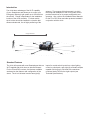
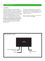
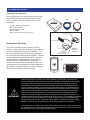
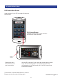
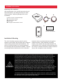
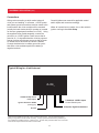
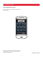
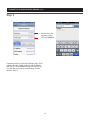
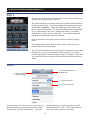
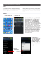
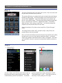
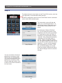
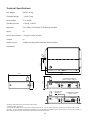
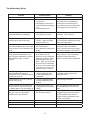
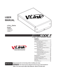
USER MANUAL vLinkTM Series Models: VLNK-Z3 VLNK-RLS VLNK-U Contents: Introduction2 Standard Features 2 vLink Controller Installation 3 Z3 Siren Application 4 RLS Siren Application 7 Universal Application 10 Your Smartphone 13 vLink Setup For Apple 14 vLink Setup For Android 19 Configuring Your vLink Menu 24 Technical Specifications 25 Compliance and Approvals 26 Troubleshooting Guide 27 Notes28 Warranty29 Product Returns 29 IMPORTANT: Read all instruction and warnings before installing and using. INSTALLER: This manual must be delivered to the end user of this equipment. Note: For more up-to-date User Manual, check C3vLink.com Introduction The vLink takes advantage of the Wi-Fi capability antenna. The purpose of this document is to aid in the setup and installation of the vLink system, and to provide instructions for its proper configuration and operation. Also, refer to the Installation/User Manuals for the Z3 or RLS Siren and other products installed in conjunction with the vLink. of your Smartphone and allows you to control your Emergency Warning Light system up to 300 feet from the vehicle. Range is dependant on the installation location of the vLink controller. For best results, the vLink box should be installed in a location that allows unobstructed, line-of-sight positioning of the range 300 feet Standard Features inputs for control switch inputs from a siren lighting control or switch pack, and eight (8) solid state outputs capable of driving up to 5A loads with a maximum combined load of 30A for the eight outputs (see Technical Specifications). The vLink will operate with most Smartphones that are Wi-Fi enabled and which have an Internet Browser. For the Z3 and RLS versions, the features available are based on the features and configuration of the sirens. The vLink Universal version has eight (8) 2 vLink Controller Installation The typical vLink controller installation is shown in Figure 1.a and 1.b below. Sedan - For sedan applications, the vLink controller is typically mounted on the rear window shelf for best “Signal” or “WiFi” reception. SUV - For SUV applications, the vLink controller is typically mounted on the roof liner in the back lefthand corner for best “Signal” or “WiFi” reception. Figure 1.a Figure 1.b vLink controller Figure 2 shows the power cable and the Z3 data cable. Figure 2 3 Z3 SIREN APPLICATION Unpacking & Pre-Installation After unpacking the vLink, carefully inspect the unit and associated parts for any damage that may have been caused in transit. Report any damage to the carrier immediately. L2 L1A L2B L1 Modular Expansion Unit NOTE: Not to Scale 20A 2 1 5 4 3 EXTERNAL Z3 Ampiflier GND GND 12V 3L CONTROLUT /OUTP INPUT +12VDC 7 6 10 9 8 ASTK USB Installation & Mounting rt-4 Po The vLink Controller may be mounted in various locations in the vehicle, but the range may be reduced if the mounting location obstructs the antenna. The choice of mounting location is of critical importance for best range and communications reliability. Choose a mounting location that allows the vLink controller’s antenna to have an unobstructed view through the vehicles windows. When selecting a mounting location, also consider the wiring requirements. Be certain that the vLink controller is securely fastened to the vehicle in a location that will not cause a hazard or injury to the occupants in case of accident. Po rt-1 Z3 Control Head Po rt-2 rt-5 AMP-2 B A D C Po CONT HEAD E rt-6 F H G Po CC LIGHT ASTK BAR 12V AUX Contents of vLink™ Z3 package: vLink Z3 controller Communications cable Power cable vLink app for Z3 siren menu screen Po rt-3 vLink-Z3 All devices should be mounted in accordance with the manufacturer's instructions and securely fastened to vehicle elements of sufficient strength to withstand the forces applied to the device. Ease of operation and convenience to the operator should be the prime consideration when mounting the siren and controls. Adjust the mounting angle to allow maximum operator visibility. Do not mount the Hand-Held Controller in a location that will obstruct the drivers view. Mount the Hand-Held Controller mounting base in a convenient location to allow the operator easy access. Devices should be mounted only in locations that conform to their SAE identification code as described in SAE Standard J1849. For example, electronics designed for interior mounting should not be placed underhood, etc. Controls should be placed within convenient reach* of the driver, or if intended for two person operation, the driver and/or passenger. In some vehicles, multiple control switches and/or using methods such as “horn ring transfer” which utilizes the vehicle horn switch to toggle between siren tones may be necessary for convenient operation from two positions. *Convenient reach is defined as the ability of the operator of the siren system to manipulate the controls from their normal driving/riding position without excessive movement away from the seat back or loss of eye contact with the roadway. 4 Z3 SIREN APPLICATION (cont.) Connections Route the control cable from the vLink Controller to the Z3 Siren and connect per the User Manual. For Z3 installations, route the CAT5 cable from the vLink Controller to the Z3. Connect the CAT5 cable to the “AMP-2” port on the Z3. Wiring varies according to which model variant of vLink you are installing. In all cases, +12VDC power and system ground connections must be routed to the location where the vLink controller will be mounted (usually the back window shelf for a sedan or inverted on the rear compartment headliner for a SUV.) Using the supplied Power Cable assembly, connect the red wire to a +12VDC Ignition Power source that is fused at 1A. It’s important that the vLink be powered from an Ignition switch power source so that a Power On Reset occurs each time the vehicle is started. Connect the black wire to vehicle ground at a point that offers a low resistance path to the battery’s negative terminal. When all connections are made, turn on the vehicle’s ignition and begin the vLink Setup. Typical Wiring for vLink-Z3 vLink TM Ignition Switched +12VDC (fused @ 1A) Z3 Siren Connection (CAT 5) Ground 5 Z3 SIREN DEFAULT MENU Z3 Default Menu Screen Initial activation of your Z3 vLink app will show the screen below. Z3 Control Button Pressing the Z3 Control button activates the Z3 siren control interface. Home Button Pressing the Home button returns you to your home screen. With the Z3 and RLS versions of vLink, select the control button to switch to the full control head graphic. This mode works best when the Smartphone is held horizontally. All of the Z3 and RLS control head buttons are functional. To switch back to the Main Menu Buttons, close the Browser and start the main vLink App again. continue on to page 13 6 RLS SIREN APPLICATION Unpacking & Pre-Installation After unpacking the vLink, carefully inspect the unit and associated parts for any damage that may have been caused in transit. Report any damage to the carrier immediately. Contents of vLink™ RLS package: vLink RLS controller Communications cable Power cable vLink app for RLS siren menu screen Modular Expansion Unit NOTE: Not to Scale RLS Control Head Installation & Mounting The vLink Controller may be mounted in various locations in the vehicle, but the range may be reduced if the mounting location obstructs the antenna. The choice of mounting location is of critical importance for best range and communications reliability. Choose a mounting location that allows the vLink controller’s antenna to have an unobstructed view through the vehicles windows. When selecting a mounting location, also consider the wiring requirements. Be certain that the vLink controller is securely fastened to the vehicle in a location that will not cause a hazard or injury to the occupants in case of accident. vLink-RLS T11369 Adapter w/ T10957 Cable S71660 USB/RS232 Adapter If no COM Port is Available Additional Required Equipment All devices should be mounted in accordance with the manufacturer's instructions and securely fastened to vehicle elements of sufficient strength to withstand the forces applied to the device. Ease of operation and convenience to the operator should be the prime consideration when mounting the siren and controls. Adjust the mounting angle to allow maximum operator visibility. Do not mount the Hand-Held Controller in a location that will obstruct the drivers view. Mount the Hand-Held Controller mounting base in a convenient location to allow the operator easy access. Devices should be mounted only in locations that conform to their SAE identification code as described in SAE Standard J1849. For example, electronics designed for interior mounting should not be placed underhood, etc. Controls should be placed within convenient reach* of the driver, or if intended for two person operation, the driver and/or passenger. In some vehicles, multiple control switches and/or using methods such as “horn ring transfer” which utilizes the vehicle horn switch to toggle between siren tones may be necessary for convenient operation from two positions. *Convenient reach is defined as the ability of the operator of the siren system to manipulate the controls from their normal driving/riding position without excessive movement away from the seat back or loss of eye contact with the roadway. 7 RLS SIREN APPLICATION (cont.) Connections Route the control cable from the vLink Controller to the RLS Siren and connect per the User Manual. The RLS installation will require the use of the RLSEXP Modular Expansion Unit and a T11940 Modular Cable. Route the T11940 cable from the vLink to the PC Port on the RLSEXP. Connect the RLSEXP to the RLS Siren using the cables provided with the kit. Wiring varies according to which model variant of vLink you are installing. In all cases, +12VDC power and system ground connections must be routed to the location where the vLink controller will be mounted (usually the back window shelf for a sedan or inverted on the rear compartment headliner for a SUV.) Using the supplied Power Cable assembly, connect the red wire to a +12VDC Ignition Power source that is fused at 1A. It’s important that the vLink be powered from an Ignition switch power source so that a Power On Reset occurs each time the vehicle is started. Connect the black wire to vehicle ground at a point that offers a low resistance path to the battery’s negative terminal. When all connections are made, turn on the vehicle’s ignition and begin the vLink Setup. Typical Wiring for vLink-RLS vLink Ignition Switched +12VDC (fused @ 1A) TM RLS Siren Connection (RLSEXP PC Port)* Ground *RLS Modular Expansion Unit and T11940 cable required. 8 RLS SIREN DEFAULT MENU RLS Default Menu Screen Initial activation of your RLS vLink app will show the screen below. RLS Control Button Pressing the RLS Control button activates the RLS siren control interface. Home Button Pressing the Home button returns you to your home screen. With the RLS versions of vLink, select the control button to switch to the full control head graphic. This mode works best when the Smartphone is held horizontally. All of the RLS control head buttons are functional. To switch back to the Main Menu Buttons, close the Browser and start the main vLink App again. continue on to page 13 9 UNIVERSAL APPLICATION Unpacking & Pre-Installation After unpacking the vLink, carefully inspect the unit and associated parts for any damage that may have been caused in transit. Report any damage to the carrier immediately. Contents of vLink™ Universal package: vLink Universal controller Communications cable Power cable vLink app for Universal menu screen Your Control Less functionality than Z3 or RLS sirens Installation & Mounting antenna to have an unobstructed view through the vehicles windows. When selecting a mounting location, also consider the wiring requirements. Be certain that the vLink controller is securely fastened to the vehicle in a location that will not cause a hazard or injury to the occupants in case of accident. The vLink Controller may be mounted in various locations in the vehicle, but the range may be reduced if the mounting location obstructs the antenna. The choice of mounting location is of critical importance for best range and communications reliability. Choose a mounting location that allows the vLink controller’s All devices should be mounted in accordance with the manufacturer's instructions and securely fastened to vehicle elements of sufficient strength to withstand the forces applied to the device. Ease of operation and convenience to the operator should be the prime consideration when mounting the siren and controls. Adjust the mounting angle to allow maximum operator visibility. Do not mount the Hand-Held Controller in a location that will obstruct the drivers view. Mount the Hand-Held Controller mounting base in a convenient location to allow the operator easy access. Devices should be mounted only in locations that conform to their SAE identification code as described in SAE Standard J1849. For example, electronics designed for interior mounting should not be placed underhood, etc. Controls should be placed within convenient reach* of the driver, or if intended for two person operation, the driver and/or passenger. In some vehicles, multiple control switches and/or using methods such as “horn ring transfer” which utilizes the vehicle horn switch to toggle between siren tones may be necessary for convenient operation from two positions. *Convenient reach is defined as the ability of the operator of the siren system to manipulate the controls from their normal driving/riding position without excessive movement away from the seat back or loss of eye contact with the roadway. 10 UNIVERSAL APPLICATION (cont.) Connections Consult lightbar user manual for applicable control switch inputs and connect accordingly. Wiring varies according to which model variant of vLink you are installing. In all cases, +12VDC power and system ground connections must be routed to the location where the vLink controller will be mounted (usually the back window shelf for a sedan or inverted on the rear compartment headliner for a SUV.) Using the supplied Power Cable assembly, connect the red wire to a +12VDC Ignition Power source that is fused at 1A. It’s important that the vLink be powered from an Ignition switch power source so that a Power On Reset occurs each time the vehicle is started. Connect the black wire to vehicle ground at a point that offers a low resistance path to the battery’s negative terminal. When all connections are made, turn on the vehicle’s ignition and begin the vLink Setup. Typical Wiring for vLink-Universal vLink 10 AWG 30 Amp Fused Power Input* TM 8 Switched +12VDC Inputs Control Switch Inputs Ignition Switched +12VDC (fused @ 1A) 8 Outputs, High Side Switched Ground *Route the red 10AWG wire to a high current +12VDC power source. You may extend this wire by splicing a longer section of like wire as necessary. It’s very important that this wire be protected by a user supplied fuse installed near the +12VDC source. The fuse rating should be about 125% of the total current for all outputs combined but must not exceed 30A. 11 UNIVERSAL DEFAULT MENU Universal Default Menu Screen Initial activation of your Universal vLink app will show the screen below. The vLink Universal version Setup button takes you to the configuration screen as previously described for the Z3 & RLS Setup section. continue on to page 13 12 Your Smartphone Based upon your type of Smartphone, follow the vLink Setup instructions on the following pages: Android® Phone Apple® Phone vLink compatible with many other Smartphones too 13 VLINK SETUP FOR APPLE BASED PHONES Setup Open the Settings Utility and select the WI-FI option. You will see a list of the WI-FI systems that are within range of the phone. The screen will look something like this: The following information outlines the setup using an Apple iPhone. Other Smartphones are slightly different in appearance but basically similiar. Step 1 1. Touch the Code3CTL network name to select. 2. Cancel this login and go back to Settings, WI-FI network settings. 3. Select to edit network settings and go to Step 2. The default SSID for the vLink is Code3CTL. For security reasons, you will want to change the SSID during setup. There are several steps necessary to get the initial network settings right. First, select the Code3CTL network name and the phone will attempt to join the network. The phone will automatically switch to a Login page. Cancel the Login page and open the Wi-Fi settings utility again. Now, touch the arrow at the right side of the Code3CTL. As shown in Step 2, a setup page will appear that allows you to select specific settings for the initial vLink network settings. Now, go back to the Settings/Wi-Fi page (as shown in Step 1) and touch the Code3CTL network name to connect to the vLink and continue with Step 2. Complete Step 2 by closing the Settings Utility. Then, open the Browser (Safari) and type the IP address 192.168.30.1 in the address line and hit the GO key. This will take you to the vLink Main Menu Screen shown in Step 3. 14 VLINK SETUP FOR APPLE BASED PHONES (cont.) Step 2 1. Set both Auto-Join and Auto-Login to OFF for Code3CTL. Complete Step 2 by closing the Settings Utility. Then, open the Browser (Safari) and type the IP address 192.168.30.1 in the address line and hit the GO key. This will take you to the vLink Main Menu Screen shown in Step 3. 15 VLINK SETUP FOR APPLE BASED PHONES (cont.) Step 3 The photo at left shows the vLink main menu screen. Now, touch the vLink logo and the vLink setup screen will load. This screen will allow you to select the function of each button and change the label on each button. Scroll to the bottom of this screen and you will see the SSID “Code3CTL”. Select the SSID window by touching it and type in a new network name. This name should be something meaningful to you - something like “OCPD117” (department initials + car number). Write this down, you’re going to need it later. You can also change the Password, but we will leave that for a later step. Scroll to the bottom of the setup screen, and hit the “Submit Changes” button. The changes will be saved. Now, go back to Step 1 and join the new network that you have just created. Once you have successfully connected using the new network name, select the right arrow (>) on your new network name (see Step 1). A network setup screen similar to that shown below in Step 4, will appear. Verify that your new SSID is shown on the top line, and set the switches as shown in Step 4. Step 4 Your new SSID should be showing here 3. Return to Wi-Fi Networks Page 2. Set Auto-Join ON 1. Set Auto-Login OFF You can create a vLink ICON on your home screen by hiting the send button (shown bottom-center in Step 3) and selecting “Add to Home Screen”. You will be given an opportunity to type a name for the ICON. The default name is “vLink”. The ICON provides an easy way to quickly start your vLink App. 16 VLINK SETUP FOR APPLE BASED PHONES (cont.) Step 4 To configure the main menu buttons on the Z3 and RLS versions, touch the vLink logo within 10 seconds after starting the App. The button configuration menu for the vLink Universal version is accessed via the control button (bottom right). The button editor screen will load and allow you to scoll through buttons A - H, and set the function of each button and edit the button name as shown on the screen. By selecting the “Button X Definition” box, you can select the function of that button and set a time value (in seconds) for Timed Mode or check the “Button X Momentary” box if Momentary operation is desired. Note: If Momentary operation is selected, any Time Delay value is ignored. When you select the “Name” box, the system keyboard will pop up and you can edit the button legend to suit your application. You can use any language that is supported by your phone. Each time you edit the settings, you should scroll to the bottom of the screen and hit the “Submit Changes” button to store the changes. You can set a button’s function to operate as a momentary switch. The Air Horn is a good example of a function that should be set to operate as a momentary switch. This will match the function of the Z3 Siren or RLS Siren Controller’s Air Horn button. 17 VLINK SETUP FOR APPLE BASED PHONES (cont.) Step 5 After you have edited the Main Menu buttons and have everything set as desired, it’s time to create a unique password for your vLink system. Note: Since the vLink uses “password” as it’s default password, “password” should not be part of your unique password. Again, write your password down and keep it in a safe location, you’ll neeed it later. Once you have changed the default password, you’ll be asked to enter your SSID and password any time you make changes in the vLink Main Menu buttons. Any electronic device may create or be affected by electromagnetic interference. After installation of any electronic device, operate all equipment simultaneously to insure that operation is free of interference. continue on to page 24 18 VLINK SETUP FOR ANDROID BASED PHONES Setup The following information outlines the setup using an Android Phone. Other Smartphones are slightly different in appearance but basically similiar. Open the Settings Utility and select the WI-FI option. You will see a list of the WI-FI systems that are within range of the phone. The screen will look something like this: Step 1 1. Select Settings Utility 2. Select Wi-Fi Tab The default SSID for the vLink is Code3CTL. For security reasons, you will want to change the SSID during setup. There are several steps necessary to get the initial network settings right. First, select the Code3CTL network name and the phone will attempt to join the network. The phone will automatically switch to a Login page. Cancel the Login page and open the Wi-Fi settings utility again. Now, touch the arrow at the right side of the Code3CTL. As shown in Step 2, a setup page will appear that allows you to select specific settings for the initial vLink network settings. Now, go back to the Settings/Wi-Fi page (as shown in Step 1) and touch the Code3CTL network name to connect to the vLink and continue with Step 2. Complete Step 2 by closing the Settings Utility. Then, open the Browser (Chrome) and type the IP address 192.168.30.1 in the address line and hit the GO key. This will take you to the vLink Main Menu Screen shown in Step 3. 3.Select the desired network (Code3CTL) 4. Connect 19 VLINK SETUP FOR ANDROID BASED PHONES (cont.) Step 2 The Android operating system does not have the Auto Login option as shown for the iPhone. So you won’t need to set Auto Login to off as described for the iPhone setup process. Complete Step 2 by closing the Settings Utility. Then, open the Browser (Chrome) and type the IP address 192.168.30.1 in the address line and hit the GO key. This will take you to the vLink Main Menu Screen shown in Step 3. 20 VLINK SETUP FOR ANDROID BASED PHONES (cont.) Step 3 The photo at left shows the vLink main menu screen. Now, touch the vLink logo and the vLink setup screen will load. This screen will allow you to select the function of each button and change the label on each button. Scroll to the bottom of this screen and you will see the SSID “Code3CTL”. Select the SSID window by touching it and type in a new network name. This name should be something meaningful to you - something like “OCPD117” (department initials + car number). Write this down, you’re going to need it later. You can also change the Password, but we will leave that for a later step. Scroll to the bottom of the setup screen, and hit the “Submit Changes” button. The changes will be saved. Now, go back to Step 1 and join the new network that you have just created. Once you have successfully connected using the new network name, select the right arrow (>) on your new network name (see Step 1). A network setup screen similar to that shown below in Step 4, will appear. Verify that your new SSID is shown on the top line, and set the switches as shown in Step 4. Step 4 vLink ICON 1. Return to Wi-Fi Networks Page You can create a vLink ICON on your home screen by hiting the send button (shown bottom-center in Step 3) and selecting “Add to Home Screen”. You will be given an opportunity to type a name for the ICON. The default name is “vLink”. The ICON provides an easy way to quickly start your vLink App. 21 VLINK SETUP FOR ANDROID BASED PHONES (cont.) Step 4 To configure the main menu buttons on the Z3 and RLS versions, touch the vLink logo within 10 seconds after starting the App. The button configuration menu for the vLink Universal version is accessed via the control button (bottom right). The button editor screen will load and allow you to scoll through buttons A - H, and set the function of each button and edit the button name as shown on the screen. By selecting the “Button X Definition” box, you can select the function of that button and set a time value (in seconds) for Timed Mode or check the “Button X Momentary” box if Momentary operation is desired. Note: If Momentary operation is selected, any Time Delay value is ignored. When you select the “Name” box, the system keyboard will pop up and you can edit the button legend to suit your application. You can use any language that is supported by your phone. Each time you edit the settings, you should scroll to the bottom of the screen and hit the “Submit Changes” button to store the changes. You can set a button’s function to operate as a momentary switch. The Air Horn is a good example of a function that should be set to operate as a momentary switch. This will match the function of the Z3 Siren or RLS Siren Controller’s Air Horn button. 22 VLINK SETUP FOR ANDROID BASED PHONES (cont.) Step 5 After you have edited the Main Menu buttons and have everything set as desired, it’s time to create a unique password for your vLink system. Note: Since the vLink uses “password” as it’s default password, “password” should not be part of your unique password. Again, write your password down and keep it in a safe location, you’ll need it later. Once you have changed the default password, you’ll be asked to enter your SSID and password any time you make changes in the vLink Main Menu buttons. Any electronic device may create or be affected by electromagnetic interference. After installation of any electronic device, operate all equipment simultaneously to insure that operation is free of interference. continue on to page 24 23 Configuring Your vLink Menu Screen You have the ability to customize eight buttons on your screen to meet individual requirements. The bottom right button is set by default according to the vLink controller application you purchased. Standard Default Button for: Z3 Siren Application RLS Siren Application Universal Application User-definable text (max. 2 lines text; 8 letters each) 24 Technical Specifications: Unit Weight: .84 lbs (.38 kg) Packaged Weight: ~1.6 lbs (.8 kg) Input Voltage: 10 to 16VDC Operating Current: <.14 A @ 13.8VDC* Approvals: FCC (USA), IC (Canada), ETSI (Europe) Certified Inputs: 8** Input Control Current: <.01A @ 13.8VDC nominal Outputs: 8** Output Current: 5A Max per output (30A combined total all outputs) Dimensions: R0 2.35 0.19 .09 6.56 7.40 4.50 2.42 1.47 vLink Z3 & RLS Controller Model No. VLNK-Z3; VLNK-RLS +12 VDC POWER + - 10 AWG 30 AMP FUSED POWER INPUT*** +12 VDC POWER + - COMMUNICATION PORT vLink Universal Controller Model No. VLNK-U CONTROL INPUT OUTPUT H G F E D C B A A B C D E F GH *Excluding output load current for Universal Output version **Universal Output version only ***Route the red 10AWG wire to a high current +12VDC power source. You may extend this wire by splicing a longer section of like wire as necessary. It’s very important that this wire be protected by a user supplied fuse installed near the +12VDC source. The fuse rating should be about 125% of the total current for all outputs combined but must not exceed 30A. 25 Compliance and Approvals Contains FCC ID: W7OMRF24WG0MAMB This device complies with Part 15 of the FCC Rules. Operation is subject to the following two conditions: (1) This device may not cause harmful interference, and (2) This device must accept any interference received, including interference that may cause undesired operation. This equipment has been tested and found to comply with the limits for a Class B digital device, pursuant to part 15 of the FCC Rules. These limits are designed to provide reasonable protection against harmful interference in a residential installation. This equipment generates, uses and can radiate radio frequency energy, and if not installed and used in accordance with the instructions, may cause harmful interference to radio communications. However, there is no guarantee that interference will not occur in a particular installation. If this equipment does cause harmful interference to radio or television reception, which can be determined by turning the equipment off and on, the user is encouraged to try to correct the interference by one or more of the following measures: • Reorient or relocate the receiving antenna. • Increase the separation between the equipment and receiver. • Connect the equipment into an outlet on a circuit different from that to which the receiver is connected. • Consult the dealer or an experienced radio/TV technician for help. To satisfy FCC RF exposure requirements for mobile and base station transmission devices, a separation distance of 20 cm or more should be maintained between the antenna of this device and persons during operation. To ensure compliance, operation at closer than this distance is not recommended. The antenna(s) used for this transmitter must not be co-located or operating in conjunction with any other antenna or transmitter. Canada - Contains IC: 7693A-24WG0MAMB The MRF24J40MB module has been certified for use in European countries. The following testing has been completed: Test standard ETSI EN 300 328 V1.7.1 (2006-10): • Maximum Transmit Power • Maximum EIRP Spectral Density • Frequency Range • Radiated Emissions Test standards ETSI EN 301 489-1:2008 and ETSI EN 301 489-17:2008: • Radiated Emissions • Electrostatic Discharge • Radiated RF Susceptibility 26 Troubleshooting Guide Problem Probable Cause Remedy I cannot connect to my vLink. • Attempting to connect to the wrong vLink. • Attempting to connect to a vLink that has the password set. • vLink already in use. Several factors could cause this. Be certain that you are attempting to connect to the vLink network; in a shop environment, check that others within range have not connected. I start to connect, but the phone asks me for the SSID and a password. • vLink SSID and password have been set by user. SSID and password are required info to connect. This is normal. Each time I try to connect to vLink a screen pops-up which says login. • This is seen on the Apple iPhone. Apple auto login feature is set to on. Go to the apple settings utility and edit the vLink network settings by turning off the auto login option. During the setup process, when I type in the IP address, the vLink main menu (as shown in the manual) never loads. •Phone is not connected to the vLink network. •vLink address is being typed wrong. Check to be certain that you are connected to the vLink network. Check to be sure that you are typing the correct ip address “192.168.30.1”. I have successfully completed the setup process and tested the vLink with my system installation, but while demonstrating it later, I couldn’t connect. •You may not have completed the setup process by entering a unique password. Under this condition, others would be able to join your vLink. Note: only one phone at a time may be connected to vLink. So, if someone else connects to your vLink, you will not be able to connect. Turn the vLink OFF/ON and then quickly connect. Once connected, complete the setup process by creating a unique ssid and password. I have changed my vLink password from the default “password” to “password1” but I’ve found that others can still join my vLink. • Your unique password cannot include any form of the default password “password”. Change the SSID and password to something that is unique and meaningful to you. Even though my car is off, I can still connect to my vLink. • vLink is not powered from a switched ignition power source. Correct wiring connection. When I push the air horn button, the air horn locks on and I have to push the button again to turn the airhorn off. • The air horn button is not configured as a momentary switch. Enter configuration mode and check the momentary box for the air horn button. I can join the network on my VLNK-U. Why don’t I get an output when I energize any of the switches? • +12VDC is not connected to Using a 10AWG wire terminated with the 30A input terminal an appropriately sized ring terminal and user supplied fuse, connect +12VDC to the terminal stud on the VLNK-U circuit board. 27 NOTES 28 WARRANTY Code 3®, Inc.’s emergency devices are tested and found to be operational at the time of manufacture. Provided they are installed and operated in accordance with manufacturer’s recommendations, Code 3®, Inc. guarantees all parts and components (except the lamps) to a period of 1 year, LED Lighthead modules to a period of 5 years (unless otherwise expressed) from the date of purchase or delivery, whichever is later. Units demonstrated to be defective within the warranty period will be repaired or replaced at the factory service center at no cost. Use of lamp or other electrical load of a wattage higher than installed or recommended by the factory, or use of inappropriate or inadequate wiring or circuit protection causes this warranty to become void. Failure or destruction of the product resulting from abuse or unusual use and/or accidents is not covered by this warranty. Code 3®, Inc. shall in no way be liable for other damages including consequential, indirect or special damages whether loss is due to negligence or breach of warranty. CODE 3®, INC. MAKES NO OTHER EXPRESS OR IMPLIED WARRANTY INCLUDING, WITHOUT LIMITATION, WARRANTIES OF FITNESS OR MERCHANTABILITY, WITH RESPECT TO THIS PRODUCT. PRODUCT RETURNS If a product must be returned for repair or replacement*, please contact our factory to obtain a Return Goods Authorization Number (RGA number) before you ship the product to Code 3®, Inc. Write the RGA number clearly on the package near the mailing label. Be sure you use sufficient packing materials to avoid damage to the product being returned while in transit. *Code 3®, Inc. reserves the right to repair or replace at its discretion. Code 3®, Inc. assumes no responsibility or liability for expenses incurred for the removal and /or reinstallation of products requiring service and/or repair.; nor for the packaging, handling, and shipping: nor for the handling of products returned to sender after the service has been rendered. Problems or Questions? Call The Technical Assistance HOTLINE - (314) 996-2800 Code 3, Inc. 10986 N. Warson Road St. Louis, Missouri 63114-2029—USA Ph. (314) 426-2700 Fax (314) 426-1337 www.code3pse.com Code 3,® Inc., a subsidiary of Public Safety Equipment, Inc. iPhone is a registered trademark of Apple, Inc. Android is a registered trademark of Google, Inc. Revision 0, 6/13 - Instruction Book Part No. T11892 ©2013 Public Safety Equipment, Inc. Printed in USA Code 3 is a registered trademark of Code 3, Inc. 29


![[U4.91.03] Procédure IMPR_TABLE](http://vs1.manualzilla.com/store/data/006352246_1-1e7bea69c46dc6cd9b23b77f6cc416b2-150x150.png)