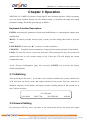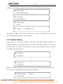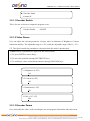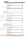
1
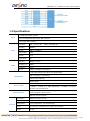
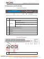
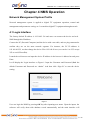
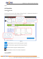
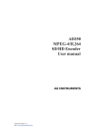
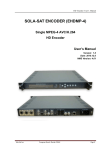
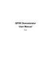
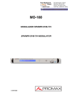
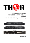
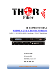
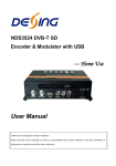
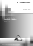
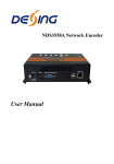
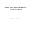
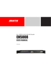
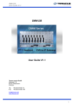
NDS3208 8 in 1 MPEG-2 Encoder User’s Manual NMS Version: 1.12.5 SW: 2.07 HW: 1.3 CHENGDU DEXIN DIGITAL TECHNOLOGY CO., LTD DIRECTORY Chapter 1 Product Introduction ............................................................................................................. 1 1.1 Outline ................................................................................................................................................ 1 1.2 Main Features ................................................................................................................................... 1 1.3 Principle Chart................................................................................................................................... 1 1.4 Specifications .................................................................................................................................... 2 1.5 Appearance and Illustration ............................................................................................................ 3 Chapter 2 Installation Guide .................................................................................................................. 5 2.1 Acquisition Check ............................................................................................................................. 5 2.2 Installation Preparation .................................................................................................................... 5 2.3 Wire’s Connection ............................................................................................................................ 7 2.4 Signal Cable Connection ................................................................................................................. 7 Chapter 3 Operation ............................................................................................................................. 10 3.1 Initializing ......................................................................................................................................... 10 3.2 General Setting ............................................................................................................................... 10 Chapter 4 NMS Operation ................................................................................................................... 17 4.1 Login Interface ................................................................................................................................ 17 4.2 Operation ......................................................................................................................................... 18 Chapter 5 Troubleshooting .................................................................................................................. 26 Chapter 6 Packing list........................................................................................................................... 27 NDS3208 8 in 1 MPEG-2 Encoder User’s Manual Chapter 1 Product Introduction 1.1 Outline The NDS3208 8 in 1 MPEG-2 Encoder is a professional SD audio & video encoding and multiplexing device. It has 8 channel CVBS video input interfaces, 8 pairs of unbalanced audio input interfaces, supporting MPEG-2 video encoding and MPEG 1 Layer 2 audio encoding. This device can simultaneously encode 8 channel SD audio & video; moreover, it has an ASI input and can multiplex the input TS with the 8 encoded SPTS to generate a MPTS output. In conclusion, its high integrated and cost effective design makes the device widely used in varieties of digital distribution systems such as cable TV digital head-end, satellite digital TV broadcasting etc. 1.2 Main Features 8×CVBS video inputs, 8 pairs of unbalanced audio inputs. 1×ASI input interface Audio MPEG-1 Layer2 Supports MPEG-2 encoding format Supports CBR Supports IP output, MPTS or 8 SPTS output over UDP, RTP/RTSP Support PCR accurate adjusting Support PID re-mapping and passthrough Support PSI/SI editing Supports PAL and NTSC SD video formats Real-time effective encoding output bit-rate monitoring Supports web NMS operation Keyboard and LCD operation 1.3 Principle Chart 1 / 29 NDS3208 8 in 1 MPEG-2 Encoder User’s Manual 1.4 Specifications 8×CVBS inputs,BNC interface Input 8 pairs of unbalanced audio inputs, BNC interface 1×ASI input, BNC interface Video Audio Resolution PAL: 720×576_50i NTSC: 720×480_60i Encoding MPEG-2 Bit-rate 1Mbps~19.5Mbps Rate Control CBR Chroma 4:2:0 Aspect Ratio 4:3 Encoding MPEG-1 Layer2 Sampling rate 48KH Resolution 24 bit Bit-rate 64Kbps~384Kbps each channel 1 ASI input multiplexed with local 8 channel SPTS Multiplexing PID re-mapping or passthrough PCR accurate adjusting PSI/SI editing 2 ×ASI outputs, BNC interface Stream output System function 1 MPTS / 8 SPTS over UDP, RTP/RTSP; 10/100Base-T Ethernet interface (uni-cast/multicast) LCD/keyboard operating, Web NMS support, Chinese-English control interface Ethernet software upgrade General Dimensions 482mm×455mm×44.5mm (WxDxH)weight Approx 4Kg Temperature 0~45℃(Operation), -20~80℃(Storage) range Power AC 110V±10%,50/60Hz or AC 220V±10%,50/60Hz requirements Power 17.6W consumption 2 / 29 NDS3208 8 in 1 MPEG-2 Encoder User’s Manual 1.5 Appearance and Illustration Front Panel Illustration: Indicate area: All indicators will light on when the device is on the current working state. 1 LCD screen Power indicator 2 TS in: input lock indicator Indicators CH1-CH8: When program has been multiplexed, the indicator will be on. 3 UP/ DOWN, LEFT/RIGHT keys 4 Enter key 5 Menu key 6 Lock key Rear Panel Illustration: 2 3 1 4 8 * CVBS input ports 3 / 29 NDS3208 8 in 1 MPEG-2 Encoder User’s Manual 2 CVBS input serial number from 1 to 8 3 Video input port 4 Audio input port (Left & Right channels) 5 ASI input port 6 2 * ASI output ports 7 Data port (for IP signal output) 8 NMS (Network management port) 9 Power Switch 10 Fuse 11 Power socket 12 Grounding Pole 4 / 29 NDS3208 8 in 1 MPEG-2 Encoder User’s Manual Chapter 2 Installation Guide 2.1 Acquisition Check When users open the package of the device, it is necessary to check items according to packing list. Normally it should include the following items: NDS3208 8 in 1 MPEG-2 Encoder User‟s Manual Analog Audio/Video Composite Input Cable ASI Cable Power Cord If any item is missing or mismatching with the list above, please contact local dealer. 2.2 Installation Preparation When users install device, please follow the below steps. The details of installation will be described at the rest part of this chapter. Users can also refer rear panel chart during the installation. The main content of this chapter including: Checking the possible device missing or damage during the transportation Preparing relevant environment for installation Installing Encoder Connecting signal cables Connecting communication port (if it is necessary) 2.2.1 Device’s Installation Flow Chart is Illustrated as following: Acquisition Check Fixing Device Connecting Grouding Wire and Power Cord Connecting Signal Wire Setting Parameter Running Device 2.2.2 Environment Requirement 5 / 29 NDS3208 8 in 1 MPEG-2 Encoder User’s Manual Item Requirement Machine Hall Space When user installs machine frame array in one machine hall, the distance between 2 rows of machine frames should be 1.2~1.5m and the distance against wall should be no less than 0.8m. Electric Isolation, Dust Free Machine Hall Floor Volume resistivity of ground anti-static material: 7 10 1X10 ~1X10 ,Grounding current limiting resistance: 1M (Floor bearing should be greater than 450Kg/㎡) Environment Temperature 5~40℃(sustainable ),0~45℃(short time), Relative Temperature 20%~80% sustainable Pressure 86~105KPa Door & Window Installing rubber strip for sealing door-gaps and dual level glasses for window Wall It can be covered with wallpaper, or brightness less paint. Fire Protection Fire alarm system and extinguisher Power Requiring device power, air-conditioning power and lighting power are independent to each other. Device power requires AC power 220V 50Hz. Please carefully check before running. installing air-conditioning is recommended 10%~90% short time 2.2.3 Grounding Requirement All function modules‟ good grounding designs are the basis of reliability and stability of devices. Also, they are the most important guarantee of lightning arresting and interference rejection. Therefore, the system must follow this rule. Coaxial cable‟s outer conductor and isolation layer should keep proper electric conducting with the metal housing of device. Grounding conductor must adopt copper conductor in order to reduce high frequency impedance, and the grounding wire must be as thick and short as possible. Users should make sure the 2 ends of grounding wire well electric conducted and be antirust. It is prohibited to use any other device as part of grounding electric circuit The area of the conduction between grounding wire and device‟s frame should be no less than 25mm2. 6 / 29 NDS3208 8 in 1 MPEG-2 Encoder User’s Manual 2.2.4 Frame Grounding All the machine frames should be connected with protective copper strip. The grounding wire should be as short as possible and avoid circling. The area of the conduction between grounding wire and grounding strip should be no less than 25mm2. 2.2.5 Device Grounding Connecting the device‟s grounding rod to frame‟s grounding pole with copper wire. 2.3 Wire’s Connection The grounding wire conductive screw is located at the right end of rear panel, and the power switch, fuse, power supply socket is just beside ,whose order goes like this, power switch is on the left ,power supply socket is on the right and the fuse is just between them. Connecting Power Cord User can insert one end into power supply socket, while insert the other end to AC power. Connecting Grounding Wire When the device solely connects to protective ground, it should adopt independent way, say, share the same ground with other devices. When the device adopts united way, the grounding resistance should be smaller than 1Ω. Caution: Before connecting power cord to NDS3208 8 in 1 MPEG-2 Encoder, user should set the power switch to “OFF”. 2.4 Signal Cable Connection The signal connections include the connection of input signal cable and the connection of output signal cable. The details are as follows: 2.4.1 Unbalanced audio and CVBS video input cable illustration: 7 / 29 NDS3208 8 in 1 MPEG-2 Encoder User’s Manual 2.4.2 ASI output cable illustration: 2.4.3 Network Cable illustration (CAT5): 2.4.4 Unbalanced audio and CVBS video input connection User can firstly find the CVBS input connector on the device according to the connector mark described on the rear panel illustration, and then connect the analog CVBS video and unbalanced audio cables (in the accessories). One end is connected to the signal source equipment while the other end to the encoder‟s CVBS input port. The encoder‟s Analog Composite Video input port and its connection are illustrated as follows: 2.4.5 ASI output interface connection 8 / 29 NDS3208 8 in 1 MPEG-2 Encoder User’s Manual User can firstly find the ASI output interface on the device according to the connector mark described on the rear panel illustration, and then connect the ASI cable (in the accessories). One end is connected to the encoder‟s ASI out connector (ASI1, ASI2) while the other end to the TS stream multiplexer or modulator‟s ASI input port. The encoder‟s ASI output interface and its connection are illustrated as follow: 2.4.6 IP Output Interface connection Users can firstly find the DATA interface on the device according to the connector mark described on the rear panel illustration, and then connect the network (CAT5). One end of the network cable is connected to the encoder‟s DATA output connector, while the other end to the TS stream multiplexer IP input port or other device which can input IP signal. The encoder‟s DATA connection is illustrated as follows: 2.4.7 NMS Connection Users can firstly find the NMS interface on the device according to the connector mark described on the rear panel illustration, and then connect the network (CAT5). One end of the network cable is connected to the encoder‟s NMS connecter, while the other end to the computer or the PC. The encoder‟s NMS connection is illustrated as follows: 9 / 29 NDS3208 8 in 1 MPEG-2 Encoder User’s Manual Chapter 3 Operation NDS3208 8 in 1 MPEG-2 Encoder‟s front panel is user operating interface. Before operating, user can decide whether directly use the default setting or customize the input and output parameters setting. The detail operations go as follows: Keyboard Function Description: ENTER: Activating the parameters which need modifications, or confirming the change after modification. MENU: To cancel presently entered value, resume previous setting and return to previous menu. LEFT/RIGHT: To move the “►” to choose or set the parameters. UP/DOWN: To modify activated parameter or page up/down when parameter is inactivated. LOCK: To Lock the screen / cancel the lock state. After pressing lock key, the system will question the users to save present setting or not. If not, the LCD will display the current configuration state. At the “Factory Configuration” page, user can press “ENTER” key to restore the factory default configuration. 3.1 Initializing After powering on the device,it will take a few seconds to initialize the system, and then the LCD will show the device name and output real-time bit-rate in the first row, while the 8 channels‟ respective serial number, and input real-time encoding bit-rate in the second row in turn. It shows as below: 8 in 1 Encoder 1P 02.94M 2P 02.73M 3P 02.92M 4P 02.90M 3.2 General Setting By pressing LOCK key, users can enter in the main menu and set the input and output 10 / 29 NDS3208 8 in 1 MPEG-2 Encoder User’s Manual parameters in the following editing interfaces, the LCD will display the following pages: ►1 System Param 2 MPTS Output Setting ►3 Mux Setting 4 Network Setting ►5 Config Setting 6 Version ►7 Language [1] English/[2] 中文 The option with “►” is the current selection, users can press the ENTER key to enter the specified submenu to modify the device parameter. 3.2.1 System Setting Under this menu, the LCD will display 8 submenus which from Encoding Channel 1 to Encoding Channel 8. The setting principle is the same for Encoding Channel 1-8, so here this manual just takes one channel as the example to explain. After pressing the enter key, the LCD will display the following pages: ►1.1 Channel 1 1.2 Channel 2 ►1.7 Channel 7 1.8 Channel 8 After users enter the submenu, the interface will turn into the following pages, and then users can enter the corresponding interface to modify the parameters. ►1 Encoder Enable ON/OFF 2 Video Param 11 / 29 NDS3208 8 in 1 MPEG-2 Encoder User’s Manual ►3 Encoder Param 4 Output IP 3.2.1.1 Encoder Enable This is for user to choose to output the program or not. Encoder Enable ON/OFF 3.2.1.2 Video Param User can adjust the relevant parameters of input video in submenus of Brightness, Contrast, Saturation and Hue. The adjustable range is 0~255, while the adjustable range of Hue is -127~ 127. The figure outside the parentheses is decimal while the inside is hexadecimal. NOTE: Below explanations are applied in this entire manual. 1) To press ENTER to start editing. 2) To move the underline through LEFT/RIGHT keys. 3) To modify the value of underlined character through UP/DOWN keys. 2.1 Brightness (0~255) 128 2.2 Contrast (0~255) 128 2.3 Saturation (0~255) 128 2.3 Hue (-127~127) 000 3.2.1.3 Encoder Param User can modify the video, audio encoding bit rate and program information under this menu. 12 / 29 NDS3208 8 in 1 MPEG-2 Encoder User’s Manual 3.1 Video Bitrate (1000-19500Kbps) 4.500Kbps 3.2 Audio Bitrate 64~320Kbps optional ► 64Kbps 3.3 Pro info 3.2.1.4 Output IP User can set the SPTS output IP parameters under this menu. The device will display the following page after users pressing the enter key. Users can decide to output the SPTS or not, and choose output 4.1 Output Enable [1] OFF 4.2 Filter Null PKT IP protocol. 4.3 Dest IP Address Users can set Destination IP Address and Port here 4.4 Destination Port 4.5 Out Bitrate (Kbps) 3.2.2 MPTS Output Setting User can set the MPTS output IP parameters under this menu. The device will display the following page after users pressing the enter key. Users can decide to output the MPTS or not, and choose output IP protocol. 2.1 Output Enable [1]OFF 2.2 Filter Null PKT 2.3 NIT Insert 2.4 Dest IP Address 2.5 Destination Port 2.6 Out Bitrate (Kbps) 13 / 29 NDS3208 8 in 1 MPEG-2 Encoder User’s Manual Users can copy a stream from the IP out streams (1 MPTS & 8 SPTS) to 2.7 ASI output [1] MPTS 2.8 TSID and ONID output through ASI. 3.2.3 MUX Setting Under this menu, user can choose programs to mux out. 3.1 Channel 1 3.2 Channel 2 3.7 Channel 7 3.8 Channel 8 3.9 ASI Channel Users can choose to remap PID or not 3.10 PID remap “Channel 1-8” represent the CVBS input. “ASI Channel” represents the ASI input. User could parse and select program(s) to mux out. The setting principle is the same for channel 1-8 and ASI Channel. Here take Channel 1 as example: 3.1 Channel 1 Press Enter key to get the program list [01]CCTV 1 Press Enter key to choose to output the program or not Choose” √ ”to output the corresponding program. Choose” × ” to not output. CCTV1 ►√ × × 14 / 29 NDS3208 8 in 1 MPEG-2 Encoder User’s Manual 3.2.4 Network Setting Users can set the network parameters by pressing the enter key, and the LCD will display the following interfaces. 4.1 NMS Interface Set the Data interface 4.2 Data Interface parameters here. 4.3Web Listen Port “4.1 NMS Interface”, user can set the parameter of NMS to connect with PC. 4.1.1 IP Address 192.168.002.136 4.1.2 Subnet Mask 255.255.255.000 4.1.3 Default Gateway 192.168.002.001 The MAC address is read-only in the keyboard operation interface, so users can just check the physical address under this interface, and the modification must be done in the network updating tools. 4.1.4 MAC Address 201012345679 NOTE: The MAC address is unique, and cannot be modified. When the MAC address is ffffffffffff, users must modify the address through special software, otherwise, the IP output data will be filter out when the IP stream passes through the router. 15 / 29 NDS3208 8 in 1 MPEG-2 Encoder User’s Manual 3.2.5 Save Configuration Users can save the modification by pressing the enter key, and it will display the following interface when user press the enter key. 5.1 Save Configuration 5.2 Restore configure 5.3 Factory Set 3.2.6 Version Users can check the device software version and hardware version, and the LCD will display the following interface when users press the ENTER key. 8 in 1 Encoder SW X.XXF HW X.XX 3.2.7 Language User can select the needed language under this submenu: Language [1]English/[2]中文 16 / 29 NDS3208 8 in 1 MPEG-2 Encoder User’s Manual Chapter 4 NMS Operation Network Management System Profile Network management system is applied to digital TV equipment operation, control and management and parameters setting, etc. It centralizes digital TV equipment through network. 4.1 Login Interface The factory default IP address is 192.168.2.136 and users can connect the device and web NMS through this IP address. Connect the PC (Personal Computer) and the device with a net cable, and use ping command to confirm they are on the same network segment. For instance, the PC IP address is 192.168.99.252, we then change the device IP to 192.168.99.xxx (xxx can be 0 to 255 except 252 to avoid IP conflict). Launch the web browser an input the device IP address in the browser‟s address bar and press Enter. It will display the Login interface as Figure-1. Input the Username and Password (Both the default Username and Password are “admin”. And then click “Sign In” to start the device setting. Figure-1 User can login the NMS by pressing OK key after inputting user name. Upon the inputs, the software will verify them with database record automatically and the main interface will 17 / 29 NDS3208 8 in 1 MPEG-2 Encoder User’s Manual appear. 4.2 Operation System→Encoder From the menu on top side of the webpage, clicking “Encoder”, it displays the information of the programs from the X encoding board as Figure-2. User can click any item here to enter the corresponding interface to check information or set the parameters Input channel selection area. The interface and setting principle of each channel are the same. User can set the parameters of the video brightness, contrast, saturation, Hue and Video/Audio Bitrate by moving respective slider. Figure-2 Click this button to reset the encoder chip and re-encoder. Click this button to apply the default setting of Input X Click this button to apply the modified parameters. Click this button to choose color schemes and patterns System→MUX 18 / 29 NDS3208 8 in 1 MPEG-2 Encoder User’s Manual Click “MUX”, it displays the interface where users can configure the Mux out MPTS. (Figure-3) Select the needed language : English and 中 文 ( Chinese ) optional Click this button to restart the device. 8 CVBS Encoding Channels 1 ASI Input Channel Output area Input area Operation area Figure-3 Configure „Input Area‟ and „Output Area‟ with buttons in „Operation Area‟. Instructions are as below: : To enable/disable the PID remapping To refresh the input program information To refresh the output program information Select one input program first and click this button to transfer the selected program to the right box to output. Similarly, user can cancel the multiplexed programs from the right box. Program Modification: The multiplexed program information can be modified by clicking the program in the „output‟ area. For example, first select the target a program in the „output‟ area, then clicking , it triggers a dialog box (Figure 4) where users can input new information. 19 / 29 NDS3208 8 in 1 MPEG-2 Encoder User’s Manual Figure-4 Input new data and click „Apply‟ button at last to confirm the modification. PID Pass: Clicking , it displays the interface where to add the PIDs which need pass through. (Figure-5) In some occasions, there are some PIDs which won‟t belong to any program, such as EPG, NIT tables and so on which user just wants to pass them through the multiplexing module without changing anything. This is the main purpose of this function. Figure-5 Click “Add” to add more boxes for filling the Input & Output PIDs, then click “Apply” to confirm. System→Output Click “Output”, it displays the interface where users can configure the IP output, it include SPTS, MPTS and ASI output. 20 / 29 NDS3208 8 in 1 MPEG-2 Encoder User’s Manual SPTS Settings: Under this menu, user can configure the 8 output SPTS parameters separately. (Figure-6) Figure-5 : To modify the output SPTS parameters as needed. By clicking this button to pop up a dialog box as below: 21 / 29 NDS3208 8 in 1 MPEG-2 Encoder User’s Manual OFF: To not output the corresponding SPTS. Input new data and click „Apply‟ button at last to confirm the modification. MPTS Settings: Under this menu, user can configure the output MPTS Parameters. (Figure-6) Figure-6 DATA IP Settings: Data IP Setting is for setting the Data parameters for the device. (Figure-6) 22 / 29 NDS3208 8 in 1 MPEG-2 Encoder User’s Manual Figure-7 ASI Output: Clicking “ASI Output” from the menu, it will display the interface as Figure-6 where to choose TS to output from ASI. Users can copy a stream from the IP out streams (1 MPTS & 8 SPTS) to output through ASI. Figure-8 System→Save load Clicking “Save Load” from the menu, it will display the screen as Figure-9. . 23 / 29 NDS3208 8 in 1 MPEG-2 Encoder User’s Manual Figure-9 System→Network When user clicks “Network”, it will display the screen as Figure-10. It displays the network information of the device. Here user can change the device network configuration as needed. Figure-10 24 / 29 NDS3208 8 in 1 MPEG-2 Encoder User’s Manual System→Password When user clicks “Password”, it will display the password screen as Figure-11. Here user can change the Username and Password for login to the device. After putting the current and new Username and Password, click Apply” to save the configuration. Figure-11 25 / 29 NDS3208 8 in 1 MPEG-2 Encoder User’s Manual Chapter 5 Troubleshooting DEXIN‟s ISO9001 quality assurance system has been approved by CQC organization. For guarantee the products‟ quality, reliability and stability. All DEXIN products have been passed the testing and inspection before ship out factory. The testing and inspection scheme already covers all the Optical, Electronic and Mechanical criteria which have been published by DEXIN. To prevent potential hazard, please strictly follow the operation conditions. Prevention Measure Installing the device at the place in which environment temperature between 0 to 45 °C Making sure good ventilation for the heat-sink on the rear panel and other heat-sink bores if necessary Checking the input AC within the power supply working range and the connection is correct before switching on device Checking the RF output level varies within tolerant range if it is necessary Checking all signal cables have been properly connected Frequently switching on/off device is prohibited; the interval between every switching on/off must greater than 10 seconds. Conditions need to unplug power cord Power cord or socket damaged. Any liquid flowed into device. Any stuff causes circuit short Device in damp environment Device was suffered from physical damage Longtime idle. After switching on and restoring to factory setting, device still cannot work properly. Maintenance needed 26 / 29 NDS3208 8 in 1 MPEG-2 Encoder User’s Manual Chapter 6 Packing list NDS3208 8 in 1 MPEG-2 Encoder 1pcs User‟s manual 1pcs Analog Audio/Video Composite Input Cable 8 pcs ASI cable 1pcs Power cord 1pcs 27 / 29