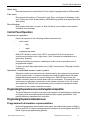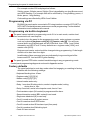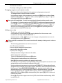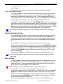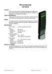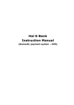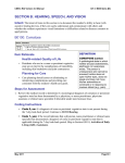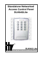
1
Standalone Networked
Access Control Panel
DLK642Lite
®
DLK642 Lite
A
C
C
E
S
S
C
O
N
T
R
O
L
P
A
N
E
L
2
Integrated Technical Vision Ltd
http://www.itvsystems.com.ua
This manual covers installation, programming and utilization of the DLK642Lite
access control panel. Read this manual carefully prior to installing and programming the unit.
Design Change Disclaimer
Information due to design changes and product improvements in this manual is
the subject to change without notice. ITV Systems reserves the right to change
the product design any time, that will subsequently affect the contents of this
manual.
ITV Systems assumes no responsibility for any mistakes that can appear in the
manual. The company guarantees that this Installation Manual is up to date and
corresponds with the unit you purchase.
Reproduction Disclaimer
All rights to this document are preserved by ITV Ltd. Copying, printing and any other
kind of unauthorised reproduction of this document or a part of it is prohibited.
Trademarks
ITV® is a registed trademark of ITV Ltd.
Training and technical support
ITV Ltd. performs training on the installation, programming and utilisation of the
DLK642Lite access control panel. For detailed information about the training and
discussing of our particular requirements to the unit please contact our personnel
by the phone numbers below.
It is recommended, for the staff intended for sales and installation of the
DLK642Lite access control panel, to take instruction courses conducted by the
ITV Systems company.
Technical support for all products of ITV Ltd. can be obtained at business time by
the phones:
+380(0)44 248 65 88
+380(0)44 248 65 89
+380(0)44 248 65 90
This support assumes the calls of trained specialists. End users must apply to
their dealers or installers before phoning us. This information is available on our
web site www.itvsystems.com.ua
http://www.itvsystems.com.ua
Integrated Technical Vision Ltd
3
4
Integrated Technical Vision Ltd
http://www.itvsystems.com.ua
Contents
Preface ........................................................................................................ 6
Benefits ....................................................................................................... 7
Features ...................................................................................................... 7
Specifications .............................................................................................. 7
What's inside? ............................................................................................. 8
General Configuration ......................................................................................... 8
Wiring Configurations .......................................................................................... 9
Mounting .................................................................................................... 11
Wiring ........................................................................................................ 12
Connecting readers ........................................................................................... 12
PIN entry, card passing ..................................................................................... 15
Cardholders codes ............................................................................................ 15
Duress code .................................................................................................... 16
Alarm output ...................................................................................................... 16
LEDs .................................................................................................................. 16
Door time ........................................................................................................... 17
Control Panel Operation ............................................................................ 17
Programming the panel in access control system composition .................. 18
Programming the panel in stand-alone use ............................................... 18
Programmed information representation .......................................................... 18
Programming via PC ......................................................................................... 18
Programming via built-in keyboard ................................................................... 18
Factory defaults ................................................................................................. 18
Previewing and modifying users codes settings ............................................... 21
Code/card deletion ............................................................................................ 22
Resetting to factory defaults .............................................................................. 23
Group card registration ..................................................................................... 23
Keyboard lockout time ....................................................................................... 24
Door A time ........................................................................................................ 24
Door B time ....................................................................................................... 24
Programming Inputs .......................................................................................... 25
Programming Outputs ....................................................................................... 26
Types of identificators ....................................................................................... 27
Readers operation ............................................................................................. 28
Setting control panel address ........................................................................... 28
Changing Code ................................................................................................. 28
Switching Day/Night Modes .............................................................................. 29
Resetting hardware to factory defaults .............................................................. 29
Limited Warranty ....................................................................................... 30
Index ......................................................................................................... 32
http://www.itvsystems.com.ua
Integrated Technical Vision Ltd
5
Preface
Preface
DLK642Lite stand-alone networked access control panel is an advanced version of
DLK641Plus stand-alone access control unit designed for use in multi-door system.
It has external specialized reader and can control two doors. In addition to
DLK641Plus functions DLK642Lite can be networked into the sophisticated access
control system using NDC-BO52 access control panel as the master controller. It
allows you expanding of simple access control system to high-end access and
security system.
DLK642Lite can be downloaded either from built-in keyboard or from PC. All
valid card numbers, time zones and relay pulse times are loaded to controller
memory. The panel can control access into two doors with no dependency on a
central computer system.
Primary goals of Access Control System are: identification of a person,
confirmation or not confirmation of access, control of movements in a necessary
zone. It can provide time and attendance logging, in addition to the usual task of
restricting individuals’ access to certain areas.
All users' access information is gathered by a server, where administrators can
retrieve and analyze the information. This data provides recording of staff
movement within an organization, whether it is a small company or a company
that employs thousands.
6
Integrated Technical Vision Ltd
http://www.itvsystems.com.ua
Benefits
Benefits
•
Proximity reader and control system integrated into one small unit
•
Easy to install, surface mounted
•
Can be attached for outdoor use
•
RS485 networking
•
Programming via own keypad or computer software
•
One engineer code
•
One master code
•
Stand-alone capacity of 998 users
•
Read range of 15 cm with internal RF antenna
•
Three LEDs provide visual annunciation
•
Power consumption 80 mA to 130 mA
•
Anti-tamper switch reporting to network
Features
•
Two doors access control
•
Three LEDs
•
Nonvolatile EEPROM stores all settings and cards
•
Two access levels
•
Eight EOL supervised inputs for Door monitoring
•
Request to Exit button and Alarm detectors monitoring
•
Tamper
•
Two relay outputs allow control of two doors
Specifications
•
Inputs
8 programmable EOL supervised inputs
•
Outputs
Two 5 A @ 24 V relays and
Two 500mA @ 24V transistors (open drain)
•
Networking
•
Power consumption:
RS485 interface
•
Supply Voltage
+10...15 VDC
•
Voltage ripple
500 mV @ 12 V
•
Standby current
80 mA
•
Maximal current 130 mA
•
Operation temperature
0 °C ... +55 °C;
•
Relative Humidity
80% relative at +35°C
•
Physical Dimensions
155x95x32 mm
•
Weight
250 g
http://www.itvsystems.com.ua
Integrated Technical Vision Ltd
7
What's inside?
What's inside?
General Configuration
Layout of DLK642Lite is shown on Diagram 1 below.
1
2
3
4
a)
7
5
6
Z6 GND Z5 Z4 GND Z3 Z2 GND Z1 GND + ER BZ
D1 D0 GN RD
X2
X3
S5
S8
S9
X2
RST
8
BAT
DLK
642
S6
VL1
S3
S4
X1
A + B- GND + EB Z7 GND Z8
-PW R+
TM
NC1 C1 NO1 NC2 C2 NO2 SA BEL
b)
1-3 - LEDs, 4 -built-in keyboard, 5 - back plate, 6 - panel PCB, 7 - PCB of the ID
reader, 8 - front cover,.
Figure 1.
a) General view of DLK642Lite,
b) DLK642Lite with front cover off.
8
Integrated Technical Vision Ltd
http://www.itvsystems.com.ua
What's inside?
Wiring Configurations
External reader
Z6 GN D Z5 Z4 GN D Z3 Z2 GN D Z1 GN D + ER BZ
Built-in reader PCB
D1 D0 GN RD
X2
X3
S5
X2
S8
S9
RST
BAT
DLK
64
2
S6
VL1
S3
S4
X1
A + B- GN D + EB Z7 GN D Z8
-PW R+
TM N C1 C1 N O1 N C2 C2 N O2 SA BEL
Panel PCB
Alarm output
Locks
Door contact
RTE button
contact
Power supply +12V
Figure 2. Terminals layout.
http://www.itvsystems.com.ua
Integrated Technical Vision Ltd
9
What's inside?
Terminals Assignment
Terminal
block
X1
Terminal
A+
BGND
+EB
Z7
GND
Z8
- PWR+
TM
NC1
C1
NO1
NC2
C2
NO2
SA
BEL
X2
Function
RS485- A
RS485- B
RS485 dropline
RS- 485 Common
+12 RS485
Zone7
Common
EOL supervised programmable
inputs 7, 8 connection
Zone8
Terminals for connecting power supply
Power
Tamper Contact
Tamper contact output (Normally closed)
Normally closed
Common
Relay 1 contacts
Normally open
Normally closed
Common
Relay 2 contacts
Normally open
Transistor output +12 V @
0,3A
For connection of executional
Transistor output (open
devices
drain) @ 0,3A
Z6
GND
Z5
Z4
GND
Z3
Z2
GND
Z1
GND
+EB
BZ
D1
D0
GN
RD
Zone 6
GND
Zone 5
Zone 4
GND
Zone 3
Zone 2
Common
Zone 1
-12V
+ 12 V
Buzzer control
DATA 1
DATA0
Green LED control
Red LED control
-
RST - reset jumper
-
S3, S4, S6 - jumpers for RS485 load selection
-
S8, S9 - reader mode setting jumpers
10
Description
Integrated Technical Vision Ltd
1-6 EOL inputs' connection
Reader connection terminals
http://www.itvsystems.com.ua
Mounting
Mounting
The controller is intended for inside mounting at 80% relative humidity.
When the panel is mounted on metal surface its reading distance decreases
Do not mount the panel or lay wires closely to the main power wiring and other sources
of electromagnetic interference
To mount the panel on the wall proceed as follows:
- Release the screw in the lower part of the cover (Figure 3a)
- Lift front cover slightly in the bottom part and pull it downwards (Figure 3b)
Fixing holes
D1 D0 GN RD
Z6 GND Z5 Z4 GND Z3 Z2 GND Z1 GND + ER BZ
X2
S5
X3
X2
S8
S9
RST
BAT
DL
K
64
2
S6
VL1
S3
S4
X1
A + B- GND + EB Z7 GND Z8 -PW R+ TM NC1 C1 NO1 NC2 C2 NO2 SA BEL
5...10mm
Fixing tabs
a)
b)
Wiring
holes
c)
d)
Figure 3. DLK642Lite mounting specifications.
- Disconnect X3 connector of built-in reader from panel PCB;
- Carefully release fixing tabs (Figure 3 c) then dismount PCB from panel base;
- Mark places for fixing holes using back plate as a template (Figure 3 d), then drill
with the 6 mm auger openings to depth of the concrete insert;
- Pull the wires
- Secure back plate with the screws
- Fix PCB on the back plate
- Connect the wires
- Connect PCB of the built-in reader to panel PCB
- Fasten front cover (Figure3a)
http://www.itvsystems.com.ua
Integrated Technical Vision Ltd
11
Wiring
Wiring
Connecting readers
DLK642Lite can control two access points using two readers. They can be readers
produced by ITV Ltd. or other readers with Wiegand interface.
X2 terminal block is intended for access point A (entrance in case of double-sided
door) reader connection. It can be iPN series reader or another one with Wiegand
interface.
X3 terminal is intended for access point B (exit in case of double-sided door) reader
connection.
Reader and controller are to be mounted on wall directly at a door at convenient
height.
The wiring is shown on Diagram below.
Built-in reader
connection
cord
Built-in reader
connection
cord
Wiegand
reader
black
red
blue
black
red
blue
S8
S9
X2
GND + ER BZ
X3
orange
green
yellow
D1 D0 GN RD
X3
white
brown
orange
green
white
GND + ER BZ
iPN series
reader
D1 D0 GN RD
S8
S9
X2
Wires colors can differ in readers of other vendors. Please refer to your reader installation manual.
External reader connecting cable length can be increased up to 50 meters by AWG
8x0.22 cable.
During increasing of cable length mind the conductors.
Do not mount the reader on metal surface. It decreases reading distance.
Reader is to be mounted at sm. minimum distance from controller. Otherwise reading
distance will be decreased.
12
Integrated Technical Vision Ltd
http://www.itvsystems.com.ua
Wiring
RTE button
Request To Exit (RTE) button is used in case
of one-sided door. Door opens on RTE
button pressing for going out.
RTE button may be used for remote door
opening - secretary or guard opens the
door, for instance.
Wiring of the normally opened RTE button is
shown on diagram. RTE is wired to Z5 and
Z6 terminals.
Rнагрузки Rнагрузки
Access
point A
RTE
button
Access
point B
RTE
button
Z6 GND Z5 Z4 GN Z3 Z2
X2
D
S5
It is not recommended to use Z7 and Z8 terminals for RTE button connection.
Usage of unblocking button on electric lock instead of RTE will cause "Door Forced"
event.
Rнагрузки
Rнагрузки
Access
point B
Door
contact
Door sensor
Access
point A
Door
contact
Door state (opened or closed) is determined by door sensor.
If door sensor is not connected, the panel is not able to
determine events of door force or unclosed door.
Wiring of normally closed door sensors to Z3 and Z4
terminals is shown on wiring diagram
It is not recommended to use Z7 and Z8 terminals for
door sensor connection.
Z6 GND Z5 Z4 GND Z3 Z2
Door sensor and RTE button connection
X2
S5
Controller inputs can be programmed for simultaneous use of
Door sensor and RTE
Rнагрузки
Rнагрузки
button.
In this case cord break means Door sensor
break and cord shortage - RTE button
pressing.
Any of eight cords can be used as a
combined one.
It is not recommended to use Z7 and Z8
terminals for combined cord connection.
Locking devices
-PWR+ TM NC1 C1 NO1 NC2 C2 NO2 SA BEL
Lock of
Access
point B
http://www.itvsystems.com.ua
Access
point A
Door
contact
and RTE
button
Z6 GND Z5 Z4 GND Z3 Z2
X2
S5
X1
Lock of
Access
point A
Access
point B
Door
contact
and RTE
button
DLK642Lite
has two relay outputs with NC and NO contacts.
They are used for connecting of power supply to
executive mechanisms, locking devices for
instance. Time and schedule of relay activating is
programmed individually for every output with the
help of engineer code.
Wiring of locking devices is shown on wiring
diagram.
Relay contact rating is 5 Amp @ 24 Volts.
Integrated Technical Vision Ltd
13
Wiring
Commutation of the inductive load, electric lock for instance, causes high energy electric
impulse induced through relay contacts. To save contacts from damage, protect them with
diode, connected in reverse to current supply of the coil.
Note the fact, that some cheap electric door strikes are not intended for being energized
for prolonged time. Program relay time as short as possible to avoid door strike coil overheating.
Sirens, Bells and agents
X1
Some sirens require polarity observing.
PW R+ TM NC1 C1 NO1 NC2 C2 NO2 SA BEL
Electric bells are often the inductive load for
power supply. During bells connection mind the
warning about the inductive load above.
Bell
+12v up to
500mA
Transistor outputs
There are two additional programmable
transistor outputs for siren, bell or other agents' control.
Bell and SA outputs are rated at
500 mA @ 24V and sink to the
ground.
TM NC1 C1 NO1 NC2 C2 NO2
+12 V
red
GND + EB
black
blue
yellow
B-
ACG
A+
PWG
It is recommended to use PSU 1,5
Rn
GND
Rn
2 кОм
2 кОм
power supply with battery backup,
manufactured by ITV Ltd. This
power good
power supply provides +12V
power rated at 1,5 A. 4AH or 7AH
battery good
battery may be used in it. PSU 1,5
Power
S4
power supply has
supply
outputs for
block
signaling of mains
power state and battery state. Wiring with mains power and
battery state by Z7 and Z8 terminals is shown on a picture.
GND
S3
-PW R+
+12 V
Power supply wiring
Z7 GND Z8
~ AC ~
These outputs are electronically
protected against overload. In
case of overload the corresponding event is generated.
Z RS-485 Interface
RS-485 Interface is used for networking of system components PC and panels. Length of RS-485 bus is up to 1200 meters.
Number of panels is up to 32.
RS-485 port is protected against over voltage (60V) and
cross polarity.
The unshielded four-wire cable may be used for RS-485 wiring.
For maximal 1200 meters distance please use 0.4 mm cross
section wire. 0.2 mm cross section wire will provide the
distance of 500 meters.
14
Integrated Technical Vision Ltd
http://www.itvsystems.com.ua
Wiring
On the first and last panel in the drop line short S3, S4, S6 jumpers to add the
resistive load.
Take care of proper grounding of all panels in the network.
Setting control panel address
Panel address is set during programming (See "Control panel address programming"
section)
Outputs' types and attributes
You can set definite function, attribute, time and one of four operating conditions for
every output that is to fix their type, during programming. (See "Controller programming").
PIN entry, card passing
PIN entry is carried out by consecutive keyboard buttons pushing. It should be
from four to ten figures length and is complete after [#] button pushing. Every
button pushing is accompanied by short built-in buzzer sound. If the entered PIN is
invalid - one long sound will be heard.
If invalid/not registered PIN or ID card is entered more than three times (this value
can be programmed) the keyboard will be blocked for time set in engineer code
programming mode. Keyboard blocking is signalled by red LED light.
Number of PIN matching attempts (from 0 to 255) is programmed using engineer
code. Number of attempts is not counted (see "Matching attempts number" section).
Door blocking time (from 0 to 255) is programmed using engineer code (see "Door
blocking time" part).
You can cancel mistaken code entering my means of [*] button.
During PIN entry 40 seconds interval cancels previous figures entering.
Proximity card (ID card) passing is equal to PIN entry. Controllers work with ASK
and FSK modulation cards.
Cardholders codes
There are several proximity card types used for controller management in
autonomous mode.
'00' card number is engineer code. All parameters are set using engineer code.
'01' card number is chief code. It allows [0] - [4] and [10] programming section
entering.
'02' - '999' code numbers are cardholders' codes.
By means of access codes/proximity cards people can:
- receive access grant;
- operate relay;
- change day and night modes.
Some information is programmed for every user individually. That is:
- access to each door grant/prohibition;
- programmed outputs operation;
- code category (1-4);
- day/night modes change permission.
http://www.itvsystems.com.ua
Integrated Technical Vision Ltd
15
Wiring
Code category
category
1
2
3
4
status
not active
active
active
active
change permission
prohibited
permitted
prohibited
permitted
access schedule
--------twenty-four-hour
day
day
Duress code
Every PIN user has additional duress code. Such code introduction leads to alarm
output engaging. When this code is entered, control panel grants access accordingly to user code access level and options and moreover alarm output switches
on.
Cardholders using proximity cards do not have duress codes.
Duress code differs from PIN code to one in the last figure (e. g. If PIN code is '123456'
then duress code will be '123457'. If PIN code is '203409' then duress code will be '203400').
Alarm output switches off after actual code entry.
Alarm output
Alarm output will be engaged at every door sensor violation, except for door time
interval on conditions that door sensor is connected to the output.
Alarm output engages on programmed time - up to 255 seconds. Alarm output does
not switch on at '0' seconds value. Alarm output time is programmed with engineer
code.
LEDs
There are three LEDs on front plate of the controller. (See figure 1)
LEDs meanings in main mode are described below:
1. LED1 (red) indicates controller operating mode (day/night)
2. LED2 (red-green) indicates controller state: norm - red LED blinks, free access green and yellow LEDs blink in turn, keyboard lockout - red LED lights continuously.
Green LED lights continuously.
LEDs programming mode meanings:
1. LED1 (red) blinks the whole programming period
2. LED2 (red-green) indicates users' codes categories and parameters
3. LED3 (green) indicates users' codes categories and parameters and figurative
volumes of controller programming settings.
Door time
If door sensor is open, the corresponding access point goes into alarm. Alarm is not
invoked, if the contact is opened during Door Time interval. This interval starts when
access is granted and lasts for programmed time or terminates on opening and
subsequent closing of door sensor.
Door time is programmed using engineer code; it can be from 0 to 255 seconds.
16
Integrated Technical Vision Ltd
http://www.itvsystems.com.ua
Control Panel Operation
Open door
Door can be open for unlimited time if 'lock' output is programmed for 255 seconds.
Free pass
Door opens at breaking of "free pass" cord. Door is left open till shortage of the
cord. Free pass mode is indicated by LED2 blinking (yellow and green light blink
alternately).
Door blocking
Door closes and does not open at "door blocking" cord violation and remains
closed till cord shortage.
Control Panel Operation
Autonomous operation
Panel can operate in the following modes autonomously:
-
main mode:
-
day,
night;
programming mode.
Red LED 2 blinks in main mode. LED 1 is switched off in day mode and
continuously switched on in night mode. (See "Autonomous exploitation programming" chapter).
Panel grants/denies access to cardholders in this mode or activates one of
programmed outputs.
In order to switch day/night modes use [1] [#] command (see "Day/night modes
switching").
Operation in networked access control system
Operation modes and indications are determined by the system during access
control system work. In external management mode the panel does not make
independent decisions as for access assignment. DLK642 Lite informs the
master controller about all events and receives commands. The panel turns into
autonomous mode when connection to the master controller is lost. All events
are registered. DLK642 Lite automatically turns to external management after
connection to the master controller renewal.
Programming the panel in access control system composition
The panel has slave function in access control system. All parameters and settings
of access points and codes/cards are determined by system possibilities. Only
panel's address is uploaded from controller.
Programming the panel in stand-alone use
Programmed information representation
Numerical parameters, downloaded to the panel, are reflected by means of built-in
buzzer and LED 2. A figure corresponds to the number of sound signals and LED 2
blinks. Figures are separated by pauses.
http://www.itvsystems.com.ua
Integrated Technical Vision Ltd
17
Programming the panel in stand-alone use
For example number 235 is displayed as follows:
2 blinks, pause, 3 blinks, pause, 5 blinks. Zero is signalled by one long Buzzer sound
and LED2 flashing. For example 040 will be reflected by 1 long flashing, pause, 4
blinks, pause, 1 long flashing.
Code settings are reflected by LEDs 2 and 3 blinks.
Programming via PC
DLK642 Lite panel can be connected to PC using interface converter NTC LNET or
NTC LNET Lite that allows easy autonomous mode programming. For the detailed
information turn to software user manual.
Programming via built-in keyboard
The panel cannot switch to programming mode if it is in main mode, resistor load
should be connected to all used outputs.
In order to turn the panel to the programming mode, enter engineer or master
code on keyboard [engineer code] [#] OR [master code] [#]. You will hear
several short sound signals and see all LEDs blink, then LEDs 1 and 2 blink
alternately and LED 3 is off. Factory defaults are: engineer code [1234], and
master code [5678].
Engineer and master code should be changed during programming. Code length
should not be less than four digits.
Invalid code or false command entry are indicated by long sound signal of the
buzzer and LED 1 red and LED 3 green flashing.
The panel ignores RTE button contact break/shortage in any programming mode.
Control panel programming diagram is enclosed in Appendix section.
Factory defaults
The panel switches to main day mode when first engaging or resetting to factory
defaults with the following settings:
- Keyboard blocking time - 40sec.
- Engineer code [1] [2] [3] [4].
- Master code [5] [6] [7] [8.].
- Internal reader works only.
- Relay 1 runs door B locking device, works in impulse mode, locking
device time is 1sec.
- Relay 2 runs bell, works in the impulse mode, time is 5 sec.
- First transistor output (SA contact) is programmed for alarm.
- Second transistor output (BEL contact) is not used.
- Single one-sided door (B) is used only.
- Cord 1 is used as door B contact sensor.
- Cord 2 is used as door B RTE button.
- Cord 3 is used as door B fire alarm input (free pass).
- Cord 4 is used as door B blocking input.
- Cords 5-8 are not used
18
Integrated Technical Vision Ltd
http://www.itvsystems.com.ua
Programming the panel in stand-alone use
- Access time is 20sec.
- Proximity cards types are ASK and FSK.
Changing engineer and master codes
Engineer code may be changed only in engineer code programming mode.
To change master code proceeds as follows:
In engineer or master code programming mode push [0] [#], then introduce [new
master code] +[#] twice. The panel will turn to the highest menu layer. To go out
of programming mode press [#] button.
New code will be admitted, if it does not coincide with already existing users' codes.
For example: To change master code [7] [7] [7] [7] in engineer programming mode
press [0] [#] (LEDs 1 and 2 blink red and LED3 blinks green synchronously), then
twice enter master code [7] [7] [7] [7] followed by [#] button pressing (LEDs 1
and 2 blink red alternately and LED 3 is off). Next [#] button pressing switches
panel to main mode (LED 2 blinks red).
Adding user code
To add user code do the following:
In programming mode push [1] [#], panel indicates first free access code
number with the help of buzzer and LED 3.
Introduce [user code] + [#], then you can change code parameters or move to
the highest menu level ([#] button).
New code will be admitted if it does not coincide with already existing users' codes or
duress codes.
The following parameters are set for new code:
- door B access permission,
- has no outputs management permission,
- cannot switch day/night modes,
- 3 (third) code category.
Code parameters change is shown in the table.
Codes categories explanation.
To go out of programming mode push [#] button.
Code categories explanations are in table below:
Next [#] button pressing switches the panel to main mode.
For example: In is necessary to add [231964] code and set point A access for it and
and proximity card for accees through points A and B.
Using engineer code programming mode press [1] [#] (LED 1 blinks red and buzzer
and green LED 3 indicate vacant code number, then LED 1 and 2 blink red and LED 3
blinks green). Enter [2] [3] [1] [9] [6] [4] [#] code, panel proceeds with code
settings editing (LED 1 blink red and LED 2 blinks yellow alternately). Press [1] [#]
buttons (LED 1 blinks red and LED 3 blinks green), switch on green LED2 and
switch off LED3 by [4] and [6] buttons pressing, then press [#] (LED 1 blinks red,
LED2 blinks yellow).
Press [#] panel turns to upper menu level (LEDs 1and 2 blink red alternately, LED 3
is switched off).
http://www.itvsystems.com.ua
Integrated Technical Vision Ltd
19
Programming the panel in stand-alone use
Press [1] [#] (LED1 blinks red, buzzer and LED3 indicate vacant code number, then
LEDs blink synchronously).
Pass a card to reader, after card code read panel proceeds with card settings
editing (LED1 blinks red LED2 blinks yellow alternately). Press [1] [#] (LED1 blinks
red LED3 blinks green). Switch on green LEDs 2 and 3 with buttons pressing. Then
section
[1] Premisses A &B
access rights
[2] Outputs
management
[3] Not used
[4]Day/night switch
right
action
[4] -for access A
[6] - for access B
[1] -relay 1
[2] -relay2
[3] - transistor output
indication
green LED2
green LED3
green LED2
red LED2
green LED3
[1]
green LED 2
[1] – 1 category
[2] – 2 category
[5] Code category
[3] – 3 category
[4] – 4 category
[#]Code parametres editing finish
yellow LED 2
green LED 3
green LED 2
green LEDs 2 и 3
press twice [#] button to move to higher menu level.
Next [#] button pressing switches control panel to the main mode.
40 seconds pause between digits entry causes panel switching to main mode.
category
1
2
3
4
status
not active
active
active
active
change permission
prohibited
permitted
prohibited
permitted
access mode
--------twenty-four-hour
day
day
Previewing and modifying users codes settings
Press [2] [#] and then enter [code number] + [#] or [code] [#] in programming
mode. Now you can edit current code parameters.
Access through access points settings
Press [1] [#] being in code parameters programming mode. Green LEDs will
reflect current parameters settings. If LED2 is on door A access is permitted, if
LED3 is on access is granted through point B.
You can change settings by pressing of [4] button - access point A switch on/off,
or [6] button - access point B. [#] button pressing returns panel to current code
parameters editing. Press [#] to move to the highest menu level. Then press [#]
again in order to exit programming mode.
Direct outputs' management
Press [1] [#] being in code parameters programming mode. LED 2 and 3 reflect
current parameters settings: green LED 2 - relay 1 management, red LED 2 - relay
2, yellow LED 2 - relays 1 and 2, green LED 3 - transistor outputs management.
20
Integrated Technical Vision Ltd
http://www.itvsystems.com.ua
Programming the panel in stand-alone use
You can change settings by pressing [1] button - relay 1 management switch on/
off, [2] -relay 2 management switch on/off, and [3]- transistor outputs switch on /
off. [#] button pressing returns the panel to current code editing. Then press [#]
to move to the highest menu level.
To exit programming mode press [#] button.
Day/night mode switch
Press [4] [#] in code parameters programming mode. LED 2 reflects current
parameters settings. Code/card can switch day/night mode if green LED 2 is on.
You can change settings by pressing [1] button. [#] button pushing returns the
panel to current code/card parameters editing. Press [#] to move to the highest
menu level.
Next [#] pressing leads exiting programming mode.
Code category
Press [5] [#] being in code parameters programming mode. Green LEDs 2 and
3 reflect current code parameters settings in double code (see Table 1).
You can change settings by pressing [1] button for category 1, [2] for category 2 ,
[3] for category 3, [4] for category 4. [#] button pressing returns panel to current
code parameters programming. Press [#] to move to the highest menu level.
Next [#] button pressing leads to exiting programming mode.
For example: It is necessary to set access grant to door A, relay 2 management
and permit cardholder switch day/night modes.
Press [2] [#] in engineer code programming mode (red LEDs 1 and 2 blink) pass a
card, panel proceeds with card settings editing (LED1 blinks red, LED2 blinks
yellow).
Press [1] [#], switch on red LED2 and switch off LED3 by [4] and [6] buttons
pressing. Press [#] (LED1 blinks red, LED 2 -yellow)
Press [2] [#], switch on red LED2 and off LED3 by [1], [2] and [3] buttons
pressing.
To switch day/night mode the code/card should have category 2 (twenty-four-hour
access).
Press [4] [#], switch on LED2 with button [1] pressing, press [#] (red LED1 and
yellow LED2 blink alternately).
Press [5] [#], then [2] [#] (red LED1 and yellow LED2 blink alternately).
Next [#] button pressing turns panel to main mode.
Code/card should have category different to 1 one for direct outputs management.
Users' codes review and editing
Press [3] [#] being in code parameters programming mode, then introduce
code number+ [#] or code itself+ [#]. The panel reflects user code/card code
with the help of buzzer sounds and LEDs blinking. [#] button pressing returns
the panel to the highest menu level. [*] button pressing allows new user code
introducing. After new code/card introduction panel turns to code parameters
programming. [#] button pushing returns the panel to the highest menu level.
http://www.itvsystems.com.ua
Integrated Technical Vision Ltd
21
Programming the panel in stand-alone use
Next [#] button pressing leads to going out of the programming mode.
For example: It is necessary to replace lost card (code number 12) by code 232002
with code settings reservation.
Press [3] [#] in engineer programming mode (red LEDs 1 and 2 blink synchronously). Press [1] [2] [#], panel indicates card code with buzzer and LED3 signals.
Press [*] (red LEDs 1-2 and green LED3 blink synchronously). Enter , panel
proceeds with current code settings' editing (red LED1 and yellow LED2 blink
alternately). Press [#] to move to upper menu level.
Next [#] button pressing switches the panel to main mode.
40 seconds pause between digits entry or cards passing causes panel switching to
main mode.
Code/card deletion
Press [4] [#] being in code parameters programming mode, then enter [code
number]+[#] or [code]+[#]. Code/card is deleted and the panel moves to upper
menu level.
Next [#] button pressing leads to exiting the programming mode.
After code/card deletion code number becomes vacant. When new code/card is registered
the smallest vacant number is chosen.
For example: It is necessary to delete code with 34 number.
Press [4] [#] in engineer code programming mode (red LEDs 1 and 2 blink synchronously). Press [3] [4] [#], code is deleted and panel moves to upper menu level
(red LEDs 1 and 2 blink and LED3 is off).
Next [#] button pressing leads to exiting the programming mode (LED2 blinks red).
Resetting to factory defaults
Press [5] [#] being in code parameters programming mode then enter [engineer
code][#]. All settings are reset to factory defaults and the panel turns to the main
mode.
All previously programmed codes/cards, engineer and chief codes are programmed
according to factory settings by reset to factory defaults operation. In case of engineer
code loss turn to hardware reset to factory defaults section.
For example: It is necessary to carry out reset to factory defaults of the panel.
Press [5] [#] in engineer code programming mode (red LEDs 1 and 2 blink synchronously), enter [engineer code] [#], reset is executed, panel is in main mode (red
LED2 blinking).
Group card registration
Press [10] [#] in code parameters programming mode then pass all cards in turn for
registration. To exit group card registration mode and move to upper menu level
press [#] button.
After next [#] button pressing panel switches to the main mode.
The following parameters are set to all cards registered in this mode:
- point B access permission,
- outputs management prohibition,
22
Integrated Technical Vision Ltd
http://www.itvsystems.com.ua
Programming the panel in stand-alone use
- no day/night switch permission,
- code category - 3.
The panel will indicate mistake at already existing card registration attempt.
Code matching attempts
Press [1] [1] [#] when been in code parameters programming mode, the panel
reflects current parameters settings by means of buzzer and LEDs. [#] button
pressing moves the panel to upper menu level. To set new parameters press [*]
button and introduce number of attempts (from 0 to 10) and [#]. Factory default is 3.
For example: It is necessary to set code matching attempts number to 5.
In engineer code programming mode press [1] [1] [#] (LED1 blinks red, buzzer and
LED3 indicate current code matching setting, then LED1 blinks red.) If current setting
differs from 5 press [*] (red LED1 and green LED2 blink synchronously). Press [5]
[#], the panel moves to upper menu level (LEDs 1 and 2 blink red alternately, LED3 is
off). To switch the panel to main mode press [#] button (LED2 blinks red).
40 seconds pause between digits entry or cards passing causes panel switching to
main mode.
Keyboard lockout time
Press [1] [2] [#] when been in code parameters programming mode, the panel
reflects current parameters settings by means of buzzer and LEDs. [#] button
pressing moves the panel to upper menu level. To set new parameters press [*]
button and introduce time (from 0 sec to 60 sec) and press [#]. Factory default is
40.
For example: It is necessary to set keyboard lockout time to 10 seconds.
When been in programming with engineer code mode press [1] [2] [#] (LED1 blinks
red, buzzer and LED3 reflect current keyboard lockout time), then red LED1 blinks. If
current setting differs from 10, press [*] (red LED1 and green LED2 blink synchronously). Press [1] [0] [#], the panel switches to upper menu level (LEDs 1 and 2
blink red alternately).
Next pressing of [#] button switches the panel to main mode (LED2 blinks red).
40 seconds pause between digits entry or cards passing causes panel switching to
main mode.
Door A time
Press [1] [3] [#] in code parameters programming mode, the panel reflects current
settings by means of buzzer and LEDs. [#] button pressing switches the panel to
upper menu level. To set new parameters press [*] button and enter time (from 0
sec to 255 sec) and press [#]. Factory default is 20.
The door will be open for unlimited time if you set time to 0 or 255 sec.
For example: It is necessary to set door A time to 30 seconds.
In engineer code programming mode (LEDs 1 and 2 blink red, LED3 is off) press [1]
[3] [#] (LED1 blinks red, buzzer and LED3 reflect current door A time, then LED1
blinks). If current setting differs from 30 press [*] (red LED1 and green LED2 blink
synchronously). Press [3] [0] [#] the panel switches to upper menu level (LEDs 1
and 2 blink red alternately, LED3 is off).
Next pressing of [#] button switches the panel to main mode (LED2 blinks red).
http://www.itvsystems.com.ua
Integrated Technical Vision Ltd
23
Programming the panel in stand-alone use
40 seconds pause between digits entry or cards passing causes panel switching to
main mode.
Door B time
Press [1] [4] [#] in code parameters programming mode, the panel reflects current
parameters settings by means of buzzer and LEDs. [#] button pressing switches
the panel to upper menu level. To set new parameters press [*] button and then
enter time in seconds (from 0 to 255) and press [#]. Factory default is 20.
The door will be open for unlimited time if you set time to 0 or 255 sec.
For example: Door B time setting is similar to door A time setting succession.
Programming Inputs
Press [1] [8] [#] in programming mode and introduce [input number] + [#]. Then you
can proceed with inputs type [1] [#] or attribute [2] [#] programming.
Inputs type
Press [1] [#] after you have chosen the number of input, the panel reflects current
input type by means of buzzer and LED 3. The panel switches to input programming
mode after [#] button pushing. To introduce new settings press [*] then enter type
number (0 or from 18 to 29) and press [#].
Inputs' types
[0] - input is not used,
[18] - door sensor,
[19] - RTE button,
[20] - both doors free pass access,
[21] - both doors blocking,
[22] - served by external program,
[23] - accumulator status,
[24] - ~220V status,
[25] - door A free pass access,
[26] - door B free pass access,
[27] - door A blocking,
[28] - door B blocking,
[29] - door sensor and RTE button.
If input type is set to the value from 1 to 17 or more than 19, the input is not used.
Inputs' attribute
Press [2] [#] you have chosen number of the input, the panel reflects current
input attribute by means of buzzer and LED 3. The panel switches to input
programming mode after [#] button pushing. To introduce new settings press [*]
then enter attribute number (0 or 1) + [#].
Input attributes
[0] - door A,
[1] - door B.
24
Integrated Technical Vision Ltd
http://www.itvsystems.com.ua
Programming the panel in stand-alone use
Attributes are important only for door sensor or RTE button type of inputs. The rest of
inputs can be programmed as [0] attribute.
For example: It is necessary to set input 2 as door B sensor.
In engineer code programming mode press [1] [8] [#] (red LEDs 1 and 2 blink
synchronously). Press [2] [#] (red LED1 and yellow LED2 blink alternately), now
press [1] [#] (LED1 blinks red, buzzer and LED3 reflect current input 2 type
setting). Press [#] to proceed with input type editing (red LED1 and green LED2
blink synchronously). Press [1] [8] [#], new value is accepted (red LED1 and
yellow LED2 blink alternately). Press [2] [#] (red LED1 blinks, buzzer and green
LED3 reflect current input 2 attribute setting). Press [#] to proceed with input
attribute editing (red LED1 and green LED 2 blink synchronously). Press [1] [#],
new value is accepted (red LED1 and yellow LED2 blink alternately).
To proceed with other inputs programming press [#] (red LEDs 1 and 2) blink
alternately). to move to upper menu level press [#] (red LEDs 1 and 2 blink
alternately, LED3 is off).
To exit programming mode and switch the panel to programming mode press [#]
(LED2 blinks red).
40 seconds pause between digits entry causes panel switching to main mode.
Programming Outputs
Press [1] [9] [#] in programming mode and enter [output number] + [#]. Then you
can proceed with outputs' type [1] [#], attribute [2][#], time [3] [#] or mode [4] [#]
programming.
Output type
Press [1] [#] after you have chosen number of the output, the panel reflects
current output type by means of buzzer and LED 3. The panel switches to output
programming mode after [#] button pushing. To introduce new settings press [*]
then enter [type number] (from 0 to 3) + [#].
Outputs' types
[0] - output is not used
[1] - lock, output is activated at valid code entering or valid card passing
[2] - bell, output is activated when access point switches to blocked mode
[3] - alarm, output is activated when access point switches to blocked mode
If you set the same type for two outputs (e.g. two bell outputs), then only the output
with the minor number will be assigned the set type.
Output attribute
Press [2] [#] after you have chosen number of the output, the panel reflects
current output attribute by means of buzzer and LED 3. The panel switches to
output programming mode after [#] button pushing. To introduce new settings
press [*] then enter [attribute number] (from 0 to 1) + [#].
Outputs attribute
[0] - door A,
[1] - door B.
Attributes are important only for type 1 (lock) output.
http://www.itvsystems.com.ua
Integrated Technical Vision Ltd
25
Programming the panel in stand-alone use
Output time
Press [3] [#] after you have chosen number of the output, the panel reflects
current output time by means of buzzer and LED 3. The panel switches to output
programming mode after [#] button pushing. To introduce new settings press [*]
then enter time (from 0 sec to 255 sec) + [#].
0 sec time setting corresponds to 0,2 sec. output engaging.
Output operating mode
Press [4] [#] after you have chosen number of the output, the panel reflects
current output operating mode by means of buzzer and LED 3. The panel
switches to output programming mode after [#] button pressing. To introduce
new settings press [*] then enter operating mode (from 1 to 4) + [#].
Outputs operating modes are:
[1] - start-stop. Output with lock type is switched off at opening of the door or at
finishing of door time interval. Output of bell or alarm type is switched off at ending
of door blocking time interval or at breaking and shorting of Blocking or Free pass
input.
[2] - impulse. Output is activated for a time set during programming.
[3] - trigger. Output is activated at each odd command and switched off at each
even command.
[4] - continuous. Lock output is switched at door opened or at finishing of door time
interval. Bell or alarm output is switched off at ending of door blocking time interval
or at breaking and shorting of Blocking or Free pass input.
For example: It is necessary to set the following parameters for output 1: door A
lock, operating time - 3 seconds, impulse operating mode.
In engineer code programming mode press [1] [9] [#] (red LEDs 1 and 2 blink
synchronously). Press [1] [#] (red LED1 and yellow LED2 blink alternately).
Press [1] [#] again (red LED1 blinks, buzzer and green LED3 reflect output 1
current type setting. Press [#] to proceed with output attribute setting (red LED1
and green LED2 blink synchronously). Press [1] [#], new value is accepted (red
LED 2 and yellow LED2 blink alternately). Press [2] [#] (red LED1 blinks, buzzer
and green LED3 reflect current output attribute setting). Press [#] to proceed
with output attribute setting (red LED1 and green LED2 blink synchronously).
Press [0] [#], new value is accepted (red LED1 and yellow LED2 blink alternately). Press [3] [#] (red LED1 blinks, buzzer and green LED3 reflect current
time of output 1 engaging). Press [#] to proceed with output time setting (red LED1
and yellow LED2 blink synchronously). Press [3] [#], new value is accepted (red
LED1 and yellow LED2 blink alternately). Press [#] to proceed with output operating
mode setting (red LED1 and green LED2 blink synchronously). Press [2] [#], new
value is accepted (red LED1 and yellow LED2 blink alternately).
To proceed with other outputs' programing press [#] (red LEDs 1 and 2 blink
synchronously). To move to upper menu level press [#] again (red LEDs 1 and 2
blink alternately, LED3 is off).
To switch the panel to main mode press [#].
40 seconds pause between digits entry causes panel switching to main mode.
26
Integrated Technical Vision Ltd
http://www.itvsystems.com.ua
Programming the panel in stand-alone use
Types of identificators
Press [2] [0] [#] in programming mode. Green LEDs 2 and 3 reflect current
settings, LED 2 corresponds to ASK modulation identificators compatibility, and LED
3 corresponds to FSK modulation identificators compatibility. Then enter identificator
type + [#] .
Identificators' types
[1] - ASK identificators,
[2] - FSK identificators,
[3] - FSK and ASK identificators simultaneously.
For example: It is necessary to program the panel for simultaneous utilization of
ASK and FSK identificators.
When been in engineer code programing mode press [2] [0] [#] (green LEDs 2 and
3 reflect current settings). Press [3] [#], new value is accepted, the panel turns to
upper menu level (red LEDs 1 and 2 blink alternately, LED3 is off).
Press [#] button to exit the programming mode and turn to the main one (LED2 blinks
red).
Readers operation
Press [2] [1] [#] in programming mode. Green LEDs 2 and 3 reflect current settings,
LED 2 corresponds to external reader operation, and LED 3 corresponds to internal
reader operation. Then enter [readers' operation mode] + [#] .
Readers' operation modes:
[1] - external reader operation solely (LED 2)
[2] - internal reader operation solely (LED 3)
[3] - both readers simultaneous operation
For example: It is necessary to program the panel for external reader use.
When been in engineer code programming mode press [2] [1] [#] (green LEDs 2
and 3 reflect current setting). Press [1] [#], new value is accepted, the panel
switches to upper menu level (red LEDs 1 and 2 blink alternately, LED 3 is off).
At next [#] button pressing the panel exits programming mode and switches to
the main one (LED2 blinks red).
40 seconds pause between digits entry causes panel switching to main mode.
Setting control panel address
Press [2] [2] [#] in programming mode, buzzer and green LED 3 indicate current
panel address settings. The panel turns to upper menu level after [#] button
pressing. To introduce new settings press [*], enter [address] (from 0 to 31) and
[#].
For example: It is necessary to set panel address for 8.
In engineer code programming mode press [2] [2] [#], buzzer and green LED3
reflect current address setting. Press [8] [#], new value is accepted, the panel
turns to upper menu level (red LEDs 1 and 2 blink alternately, LED3 is off.
Press [#] to exit programming mode and move to the main mode.
40 seconds pause between digits entry causes panel switching to main mode.
http://www.itvsystems.com.ua
Integrated Technical Vision Ltd
27
Programming the panel in stand-alone use
Changing Code
Each user of 2 and 4 code category can change a code using [*] button command.
To change a code press [*], buzzer utters three sound signals accompanied by
LEDs' flashes. Now introduce actual user code, then new user code and [#]
twice.
New user code will be accepted if the present code type has permission for
code change, if actual code is correctly introduced, and if new code does not
coincide with already existing codes or duress codes.
To exit code change programming mode press [#] button.
You cannot change engineer or master code with the method described above.
For example: [1] [2] [3] [4] [5] [6] code user wants to change the code for [6] [5]
[4] [3] [2] [1].
User should necessarily have code category 2 or 4.
Press [*] button, you will hear three long sound signals, LED2 starts to blink red.
Enter user old code [1] [2] [3] [4] [5] [6] [#], long signal will be heard. In case of
false code entry or code category 1 or 3 an error signal will be heard. Enter new
code [6] [5] [4] [3] [2] [1] [#], long signal confirms correct code entry. Enter new
code [6] [5] [4] [3] [2] [1] [#] repeatedly, long confirmatory signal will sound.
Press [#], long confirmatory sound and the panel switches to the main mode.
Switching Day/Night Modes
To switch day/night mode press [1] [#] (LED 2 blinks yellow), then enter user code
and press [#].
Red LED 1 is switched on in night mode and switched off in day mode.
28
Integrated Technical Vision Ltd
http://www.itvsystems.com.ua
Programming the panel in stand-alone use
Resetting hardware to factory defaults
1. Close TM and BEL terminals with the bridge when power is off.
2. Switch on the power, buzzer utters several short sound signals. LEDs blink
synchronously after short pause.
3. Switch off panel's power.
4. Take off TM and BEL terminals bridge.
The panel is ready for the operation.
X1
Z8
http://www.itvsystems.com.ua
-PW R+
TM NC1 C1 NO1 NC2 C2 NO2 SA BEL
Integrated Technical Vision Ltd
29
Limited Warranty
Limited Warranty
ITV Ltd. warrants that for a period of eighteen months from the date of purchase,
the product shall be free of defect in materials and workmanship under normal use
and that in fulfillment of any breach of such warranty, ITV Ltd. shall, at its option,
repair or replace the defective equipment upon return of the equipment to its repair
depot. This warranty applies only to defects in parts and workmanship and not
damaged incurred in shipping or handing, or damaged due to causes beyond the
control of ITV Ltd. such as lightning, excessive voltage, mechanical shock, water
damage, or damage arising out of abuse, alteration or improper application of the
equipment.
The foregoing warranty shall apply only to the original buyer, and is and shall be lieu
of any and all other warranties, whether expressed or implied and of all other
obligations or liabilities on the part of ITV Ltd. This warranty contains the entire
warranty. ITV Ltd. neither assumes, nor authorizes any other person purporting to
act on its behalf to modify or to change this warranty, nor to assume for it any
warranty or liability concerning this product.
In no event shall ITV Ltd. be liable for any direct, indirect or consequential damages.
Loss of anticipated profits, loss of time or any other losses incurred by the buyer in
connection with the purchase, installation or operation or failure of this product.
30
Integrated Technical Vision Ltd
http://www.itvsystems.com.ua
http://www.itvsystems.com.ua
Integrated Technical Vision Ltd
31
Index
M
C
Codes
Adding user code 19
cardholders codes 15
cards registeration 23
changing codes 28
engineer code 19
master code 19
users codes 21
Control panel address 15, 28
Duress code 16
Modes
autonomous 17
day/night modes 29
O
Outputs 10
alarm output 16
programming outputs 26
relays 7
transistor 7, 14
P
D
Defaults
factory defaults 18, 23, 29
Door sensor 13
Door sensor and RTE button
connection 13
Door time 17
Duress code 16
I
Identificators 27
Inputs 7, 10
programming inputs 25
PIN 15
Power
consumption 7
supply wiring 14
Programming 18
R
Reader
connection 12
operation 28
RTE button
connection 13
Door sensor and RTE button 13
L
060504
LEDs 16
Locking devices 13
32
Integrated Technical Vision Ltd
http://www.itvsystems.com.ua