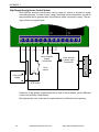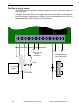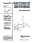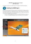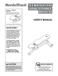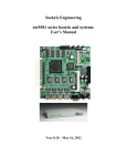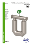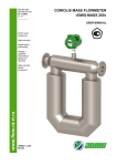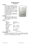
1
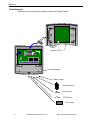
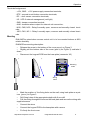
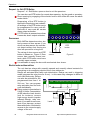
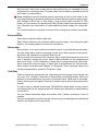
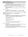
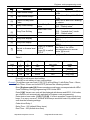
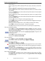
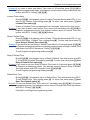
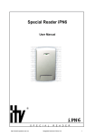
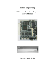
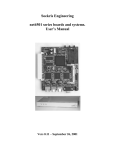
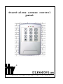
Stand-alone access control
panel
®
DLK640Plus
s t a n d - a l o n e
a c c e s s
c o n t r o l
p a n e l
2
Integrated Technical Vision Ltd
http://www.itvsystems/com/ua
This manual covers installation, programming and utilization of DLK-640Plus standalone access control unit. Read this manual carefully prior to installing and programming the unit.
Design Change Disclaimer
Due to design changes and product improvements, information in this manual is
subject to change without notice. ITV reserves the right to change product design
at any time, which may subsequently affect the contents of this manual.
ITV assumes no responsibility for any errors that may appear in this manual. ITV
will make every reasonable effort to ensure that this Installation/Programming
Manual is up to date and corresponds with the unit you purchase.
Reproduction Disclimer
All rights to this document preserved by Integrated Technical Vision Ltd. Copying,
printing and any other kind of reproduction of the document or its part without
permission of Integrated Technical Vision Ltd is prohibited.
Trademarks
ITV® is a registered trademark of Integrated Technical Vision Ltd.
Training and technical support
Integrated Technical Vision Ltd performs training on the installation, programming
and utilisation of DLK-640Plus stand-alone access control unit. For additional information about the training and discussing of your particular requirements to the
unit please contact our personnel by the phone numbers below.
For the personnel intended for sales and installation of DLK-640Plus stand-alone
access control unit on permanent basis is recommended to pass the training in
Integrated Technical Vision Ltd.
Technical support for all products of Integrated Technical Vision Ltd can be obtained at working time by the phones:
+380 (0) 44 248 65 88
+380 (0) 44 248 65 89
+380 (0) 44 248 65 90
This support assumes the calls of trained specialists. End users must apply to
their dealers or installers before calling us.
This information is available on our web site www.itvsystems.com.ua
http://www.itvsystems.com.ua
Integrated Technical Vision
3
Contents
Features .................................................................................... 6
Operation ................................................................................... 7
Mounting ......................................................................................................... 9
Request - to - Exit (RTE) Button ................................................................... 10
Door sensor .................................................................................................. 10
Electric locks and door strikes ...................................................................... 10
Duress Code ................................................................................................ 12
LEDs ............................................................................................................ 12
Control Panel Operation ........................................................... 14
Programming ............................................................................ 14
Factory defaults ............................................................................................ 14
Default times ................................................................................................ 15
Settings displaying ........................................................................................ 15
Hardware reset to factory defaults ................................................................ 15
User code settings’ editing ............................................................................ 20
User code change ........................................................................................ 20
User code review .......................................................................................... 20
[*] button programming mode ....................................................................... 21
APPENDIX 1 ............................................................................ 22
Access Control System ................................................................................ 22
High Degree Security Access Control System .............................................. 24
APPENDIX 2 ............................................................................ 28
Limited Warranty ...................................................................... 31
4
Integrated Technical Vision Ltd
http://www.itvsystems/com/ua
Preface
Preface
DLK640Plus standalone access control panel is intended for access control system creation and/or use in intruder alarm systems. The panel provides one or two
execution units control by means of code entry.
DLK640Plus is characterized by presence of nonvolatile memory, two relays, alarm
output, one engineer code, one chief code and 29 users' codes. Valid code introduction allows you relay control and day/night modes change. The panel supports
such advanced features as request-to-exit, keypad lockout, duress code, two access levels. It has three light emitting diodes (LED).
http://www.itvsystems.com.ua
Integrated Technical Vision
5
Features
Features
–
Fully programmable from the built-in keypad
–
Three LEDs
–
Built-in buzzer
–
Utilizes keypad codes from 4 to 10 digits long
–
One Master code
–
One Engineer code
–
29 user codes
–
Additional duress code for each user code
–
Two access levels
–
Two relays
–
Alarm output
–
Door sensor
–
RTE sensor
–
Tamper
Specifications
Electrical
–
Voltage
–
Power consumption
–
10 … 15 V
–
Stand-by
15 mA
–
Maximal
70 mA
Contact Rating
–
Relay
–
Alarm Output
5A @ 24 V
60 mA @ 24V
–
Voltage ripple
500mV@12V
–
Weight
200 grams
–
Dimensions
156 x 105 x 20 mm
Mechanical
Environmental
6
–
Temperature
0 … +55 C°
–
Relative humidity
80% at 25 C° (without condensate)
Integrated Technical Vision Ltd
http://www.itvsystems/com/ua
Operation
Operation
General Configuration
The view of DLK-640Plus stand-alone access control panel is shown on Figure 1
1
2
3
4
a)
7
5
6
FAC TORY SETTING
Keyb oa rd Co nne ctor X2
+12 V GND RTE DC I/O
SAB
8
AL M CM1 NC1 NO1 CM2 NC2 NO2
б)
1 - LED1,
2 - LED2,
3 - LED3,
4 - built-in keypad,
5 - blank end cover,
6 - control unit PCB,
7 - keypad PCB,
8 - front cover
http://www.itvsystems.com.ua
Integrated Technical Vision
7
Operation
Terminals Layout
Terminals layout on the main board is shown on Figure 2 below
Keypad PCB
FACTORY SETTING
Keyboard Connector X2
+12V GND RTE DC I/O
SAB ALMCM1NC1 NO1CM2NC2NO2
Panel baseplate
Alarm output
Locking devices
Door sensor
RTE button
+12 V power
8
Integrated Technical Vision Ltd
http://www.itvsystems/com/ua
Operation
Terminals Assignement
- +12V, GND - +12V power supply connection terminals;
- RTE - request-to-exit button connection terminals;
- DC - door sensor connection terminals;
- I/O - LED 2 external management (red light)
- SAB - tamper connection terminal;
- ALM - transistor alarm output for external unit connection;
- NO2, CM2, NC2 - Relay2 normally open, common and normally closed terminals;
- NO1, CM1, NC1 - Relay1 normally open, common and normally closed terminals.
Mounting
DLK-640Plus stand-alone access control unit is to be mounted indoors at 85%
relative humidity.
DLK640Plus mounting description:
–
Release the screw in the bottom of the cover pos a) on Figure 3
– Slightly pull the bottom side of the cover (pos b) on Figure 3) and take it
down
–
Disconnect the keypad PCB from the base plate (connector X3)
a)
b)
c)
J1
FACTORY
SETTING
Keyboard Connector X2
+12V GND RTE DC I/O
5...10мм
Mounting
holes
SAB ALMCM1NC1 NO1CM2NC1NO1
Wiring
holes
– Mark the position of the fixing holes on the wall, using back plate as a pattern (pos c) on Figure 3
–
Drill fixing holes of the appropriate depth with 6 mm drill
–
Pull the wiring through the holes on the back plate and secure the wiring with
supplied screws
–
Connect the wires
–
Connect the keypad PCB to the baseplate with a screw.
–
Fix firmly the front cover
http://www.itvsystems.com.ua
Integrated Technical Vision
9
Operation
Request - to - Exit (RTE) Button
Request - to - Exit Button opens a door to exit the premises.
You can also use RTE button for remote door opening - by the guard or secretary.
Direct opening by engaging of the electric lock or door strike will cause the alarm
mode switch.
Depressing of the RTE button is
identical to introducing user code #2.
All settings of the RTE button are to
be programmed for user code #2.
Removal of user code #2 causes
alarm output activation.
If RTE button is pressed more than
8 seconds, alarm output activates.
Door sensor
DLK-640Plus determines door status by means of door sensor. If you
do not use door sensor, the unit cannot detect neither door forcing nor
door left opened for a long time.
GND RTE DC I/O
SAB ALMCM1
RTE
button
The wiring of door sensor and RTE
Door
button is shown on Figure 5. Door
Figure 5
sensor
sensor has normally closed contacts, while RTE button must have
normally open contacts.
It is advisable to equip the door with mechanical door closer.
Electric locks and door strikes
The unit has two relays with normally opened and normally closed contacts for
energizing or de-energizing electric locks, door strikes etc.
Relays are activated after valid code introduction. Relays can work in triggering
mode (program the relay time for 0 sec) - in this case relay changes its state on
each valid code entry. Relays
can also be activated for the
programmed time from 1 to ND
SAB ALM CM1 NC1 NO1 CM2 NC2 NO2
254 sec. You can program
relay activation time for each
+Uпит
code individually.
Relay contact commutation is
5 A @ 24 Volts. Commutation
Lock 2
of the inductive load, electric
lock for instance, causes
high energy electric impulse
induced through relay conLock 1
tacts. If you want to save contacts from damage, protect
them with diode, connected in
reverse to the current supply
voltage of the coil.
10
Integrated Technical Vision Ltd
http://www.itvsystems/com/ua
Operation
Note the fact, that some cheap electric door strikes are not intended for been
energized for a prolonged time. Program relay time as short as possible to avoid
door strike coil overheating.
Read installation manual carefully before connecting a lock or door strike or before programming its operation parameters. Ensure that your power supply is powerful enough to drive lock or door strike. If lock or door strike requires 12 VDC
power, you can connect it in parallel with DLK-640Plus stand-alone access control
unit, otherwise you would have to install additional power supply for locking device.
It is recommended to consult the manual of the locking device before its installation.
Sirens and Bells
Some sirens require polarity observing.
Often Electric bells are the inductive load for power supply. Connecting the bells
observe the warning about the inductive load above.
Alarm output
Alarm output is an open collector transistor output. It grounds during activating.
You can utilize alarm output connecting it to the outer alarm system or the executing device with operation current less than 60 mA.
If door contact is connected to DC terminal, alarm output will activate any time the
door is opened, except entry time. Alarm output activates for the programmed
alarm time (from 1 to 254 seconds). If alarm time is programmed for 0 seconds,
alarm output will never be active. If alarm time is programmed for 255 seconds,
alarm output is activated until "Master" or "Engineer" code is entered. Alarm time
can be programmed by means of "Engineer" code.
Code Entry
Code is entered by sequential keys’ depressing on the keypad. Code length can
vary from 4 to 10 digits. Code entry is followed by pressing [#] button. Each key
pressing is accompanied by the sound of internal buzzer. Valid code is accompanied by one long sound signal. Entering of invalid code is warned by several short
sounds.
If invalid code is entered three times, DLK-640Plus stand-alone access control
unit blocks itself for the programmed time. Blocking is indicated by rapid blinking
of red LED 2.
You can cancel entereded digits succession with [*] button pressing in case of
mistake.
If no key is pressed during 40 seconds, all previously entered digits arre discarded
and the unit switches into main mode.
http://www.itvsystems.com.ua
Integrated Technical Vision
11
Operation
Codes
Several types of codes are intended for unit control.
Code #00 is Engineer code. It allows:
-
Engineer Code programming,
-
Master Code programming,
-
Users’ codes programming,
Relay operation modes and door time programming (individually for each
user code),
-
Alarm output time programming,
-
Keypad lockout time programming,
-
Reset to factory defaults.
Code #01 is Master code. It allows:
-
Master Code programming,
-
Users’ codes and their access level programming,
Codes #02 - 30 are users’ codes. They can be allowed to:
-
Drive relays
Switch day/night modes
Entering of the user code #2 is identical to RTE button pressing. Changing of
settings of user Code #2 causes changing of RTE button settings. Deletion of user
code #2 causes alarm output activation after RTE button depressing.
For each user code you can program:
- Access level from 1 to 4, define access rights (programmed by "Master"
code)
- Code options - choose relays to drive, relay time, door time (programmed by
"Engineer" code)
Duress Code
Every user, besides his regular code has an additional duress code, independently of user code access level and options. When this code is entered, DLK-640Plus
stand-alone access control unit grants access accordingly to user code access
level and options and alarm output switches on.
Duress code differs from user code in the last digit per 1. For instance, if user code
is [1][2][3][4], than duress code for this user is [1][2][3][5].
If user code ends with '9', than duress code ends with '0'. For instance, if user code
is [1][0][0][9], than duress code for this user is [1][0][0][0].
LEDs
There are three LEDs on the front panel of DLK-640Plus stand-alone access control unit. Their functioning is described below:
Main mode
LED 1 (red) indicates panel operation mode
LED 2 (Bi-colour, Red and Green): Red - indicates I/O output status, Green indicates Relay 1 status
12
Integrated Technical Vision Ltd
http://www.itvsystems/com/ua
Control Panel Operation
LED 3 (Green) - indicates Relay 2 status
Programming mode
LED 2 (Bi-colour, Red and Green): indicates access levels and user code options
and numeric values of unit settings.
LED 3 (Green) - indicates access levels and user code options.
Door time
Door time starts after relay activation.
The first break and closing of the door sensor ends door time. The warning signal
sounds, if door is opened for five seconds before door time ending. In this case
you should close the door and enter code once more to start door time again.
The door time is programmed by means of an "Engineer" code. Valid values are 0
- 253 seconds.
"Open door" state
After code with door time set to 254 sec entering the door will not be supervised for
unlimited time until it is closed.
Lockout Mode
If invalid code is entered for three times, the unit locks out for programmed time.
Lockout time can be programmed from 1 to 255 seconds. Programming this value
to 0 disables lockout mode.
http://www.itvsystems.com.ua
Integrated Technical Vision
13
Programming
Control Panel Operation
DLK-640Plus can operate in one of the following modes:
-
Main mode:
-
Day mode
-
Night mode
-
[*] button programming mode
-
"Engineer" code programming mode
-
"Master" code programming mode
-
Lockout mode
LED 1(red) continuously lights in the main mode. The unit performs actions, programmed for entered code in this mode. These actions are: Relay 1 activation,
Relay 2 activation, activation of both relays or opportunity to choose relay for activation.
Night mode of the unit is indicated by "slow" blinks of LED 1. Only codes with
access level 2 are valid in this mode.
To switch the unit into night mode enter code without control over any relay permission (see "Engineer programming mode"). This code should have access level
2, otherwise the code will be able to switch night mode on, but unable to switch a
unit into day mode.
If duress code is entered, DLK-640Plus performs actions accordingly to user code
access level and options and switches on alarm output for programmed time. Alarm
output switches on immediately after duress code entry.
If there are no keystrokes for 40 seconds a unit returns to the main mode automatically.
Program desired settings and codes before utilizing the unit.
Programming
During programming DLK-640Plus stand-alone access control unit ignores break/
opening of RTE button. Door sensor control lasts as usual.
Factory defaults
After the first switching on and after reset to factory defaults DLK-640Plus works in
the main mode with the following settings:
-
Alarm output time
-
Lockout time
40 sec
-
Engineer code
1234
-
Master code
5678
-
User code #2
[A][A][A][A]
-
Code drives
Relay1
-
Relay time
3 sec
-
Door time
15 sec
-
Access level
3
14
10 sec
Default Relay 1 time 3 sec
Integrated Technical Vision Ltd
http://www.itvsystems/com/ua
Programming
-
Default Relay 2 time 3 sec
Default door time
20 sec
Factory default of user code 2 - [A][A][A][A] - consists of several hexadecimal
digits 'A'. This is made intentionally to avoid code entry from keypad after factory
defaults resetting, but RTE button should be available for use.
Default times
There are tree "default" times - Relay 1 Default time, Relay 2 Default time and
Door Default time, made for convenience of programming the unit.
You can refer to these values while programming parameters of users’ codes. In
this case by changing only "default" time value, you will change the appropriate
values for all codes.
For instance if you enroll new user code - its relay time will be automatically set to
255. It means that as value of relay time for this code the default relay time will be
used. If you set the value of relay time to 255 for several codes it means that you
use the default relay time for all these codes. Modifying Default Relay Time, you
change the time of relay activation for all these codes.
Settings displaying
Numeric values of settings are displayed by means of built-in buzzer and LED 2.
Nonzero digit is displayed as number of short beeps and LED 2 blinks. Digits are
separated by interval.
For instance, number 235 will be displayed as follows:
2 blinks of LED 2 + 2 beeps, interval, 3 blinks of LED 2 + 3 beeps, interval, 5 blinks
of LED 2 + 5 beeps.
Digit '0' is displayed as one long sound and LED 2 flash. For instance, number 040
is displayed as follows: LED 2 lights + long sound, interval, 4 blinks of LED 2 + 4
beeps, interval, LED 2 lights + long sound.
Parameters are displayed with LED2 and LED3. Green light of LED 2 means 'YES'.
Hardware reset to factory defaults
To reset DLK-640Plus to factory defaults perform
the following actions:
1. Cut off the power
X2
3. Power on the unit. Buzzer will sound three
long beeps, then several short beeps accompanied by LEDs’ blinking. The settings correspond to factory defaults
and the panel is in "Engineer" programming mode now.
After resetting to factory defaults all user codes
will be deleted!
J1
factory preset
2. Short jumper J1
4. Take off jumper J1 with power on. Program
desired settings.
http://www.itvsystems.com.ua
Integrated Technical Vision
15
Engineer code programming mode
Engineer code programming mode
Enter [Engineers code] [#], factory setting - [1] [2] [3] [4] to switch to Engineer
code programming mode. Buzzer will sound several times accompanied with LEDs’
blinks. LED 1 blinks during the whole period of programming.
Engineer code can be changed as described in "Code change with [*] button"
Engineer code programming mode is described in APPENDIX "Engineer code
programming flowchart".
After Engineer code programming mode engaging you acquire the following possibilities:
“Master code” programming.
Enter [0][#], then new [Master code][#] and confirm it: [Master code][#].
New code will be accepted if it differs from any enrolled users’ codes and duress
codes.
Example To change Master code to 7777 in “Engineer” programming mode enter [0][#],
then [7] [7] [7] [7] [#] and once more [7] [7] [7] [7] [#].
Users’ codes enrollment
Enter [1][#]. DLK-640Plus displays the first not-used user code number with buzzer and LED 2 indications. Enter [User Code][#]. After that you can change code
settings or move to Engineer programming mode by pressing [#].
Default settings of new code are:
Code drives Relay 1
Relay Time is 255 (default time)
Door Time is 255 (default time)
Access level - 3
To view or change settings press appropriate key (see Table 1)
To exit user code settings editing mode press [#] button.
User code settings editing
Enter [2][#]. Then enter [number] of user code OR [User Code] and press [#].
LEDs 2 and 3 indicate relay operation setting for this code.
Press appropriate key for parameters change (see Table 1).
The "default" value of relay time is used if you need to set equal time for many user
codes. If you are using "default" time, changing of these values causes changes of
time for all user codes, relevant to them.
16
Integrated Technical Vision Ltd
http://www.itvsystems/com/ua
Engineer code programming mode
K ey
Function
To be follow ed by…
[1]
Code drives Relay1
[2]
Code drives Relay2
[3]
Choice of relay after
C ode
[4]
Relay Time Editing
Enter Relay Time
value
Entry Time Editing
Enter Door Time
value
[5]
Remarks
Code drives Relay 1 if LED 2
is ON
Code drives Relay 2 if LED 3
is ON
Both LED 2 and LED3 blinking
for choice
'0' - trigger mode
'255' - "default value"
'0' - no entry time
'254' - "opened door" mode
'255' - "default value"
[6],[9],[0] Reserved
Time displayed with buzzer and
LE D 2
Time displayed with buzzer and
LE D 2
[7]
Relay time display
[8]
Entry time display
[*]
Switch to Access level
setting
Press [1] to switch
LE D 2
Press [2] to switch
LE D 3
See Table 2 for LEDs
correspondence to access
levels, [#] for exit
You can edit access level of the code after pressing [*], see Table 2.
Table 2
A cce ss
level
1
LE D
1
OFF
LE D
2
OFF
User Code
is
Inert
User can change
own code
NO
Code is valid in
mode
N/A
2
OFF
ON
Active
YES
24-hour
3
ON
OFF
Active
NO
Day (only)
4
ON
ON
Active
YES
Day (only)
Press [#] to exit access level editing.
Press [#] to exit editing of user code settings.
Example To program new user code [1] [9] [7] [5], driving Relay 2, with Relay Time = 19 sec,
Door Time= 55 sec and lockout OFF, perform the following actions:
Enter [Engineer code] [#]. Buzzer sounds several beeps, accompanied with LEDs'
2 and 3 blinking. During programming LED1 blinks RED.
Enter [1][#]. Vacant user code will be displayed with buzzer and LED 2. If all codes
are used the unit automatically switches to Engineer code programming.
Enter desired user code: [1] [9] [7] [5] [#]. If code is accepted, buzzer emits long
beep. If an error occurred - several short beeps would be heard. By default new
code has the following settings:
Code drives Relay 1
Relay Time - 255 (default Relay times)
Door Time - 255 (default door time)
http://www.itvsystems.com.ua
Integrated Technical Vision
17
Engineer code programming mode
Access level - 3
Press key [1]. Green LED 2 switches OFF, that means code does not drive Relay1.
Press key [2]. LED 3 switches ON, that means code drives Relay 2.
Press key [4]. Buzzer emits continuous beep that means unit is ready for Relay
Time editing.
Press keys [1][9][#]. Buzzer emits continuous beep that means unit has accepted
new value of Relay Time.
Press key [5]. Buzzer emits continuous beep that means unit is ready for Entry
Time editing.
Press keys [5][5][#]. Buzzer emits continuous beep that means unit has accepted
new value of Entry Time.
Press key [#] to return to Engineer code programming mode.
Enter [1][2][#], Buzzer sounds continuous beep and then displays previously programmed Lockout Time.
Press [*], continuous beep sounds - unit is ready for Lockout Time editing.
Press [0][#], continuous beep sounds - changes are accepted.
Press [#], continuous beep sounds and the unit quits Engineer programming.
User code viewing and editing
Press [3][#], then [code number][#] OR [user code][#]. DLK-640Plus displays
user code. Pressing of [#] will return you to Engineer programming, pressing of [*]
allows to enter new user code.
Example If you want to change user code #3 to [0] [6] [1] [1] [7] [5] in Engineer code
programming mode:
Press [3][#], the panel displays user code.
Press [*], then [0] [6] [1] [1] [7] [5][#].
User code deletion
Enter [4][#] then [code number][#] OR [user code][#].
Example If you want to delete user code #17 press [4][#] then [1][7][#].
Panel’s reset to factory defaults
Enter [5][#], then [Engineer code][#].
After performing of this operation all previously programmed user codes are deleted and Engineer code, Master code and code #2 are programmed according to
factory defaults.
Example If Engineer code is [1] [9] [8] [8] and you want to reset DLK-640Plus stand-alone
access control panel to factory defaults, press [5] [#]. Buzzer utters nine sound
signals. Enter Engineer code: [1] [9] [8] [8].
Alarm output activation time
Enter [1] [1] [#]. Unit displays value of alarm output time with buzzer and LED 2.
Press [#] to exit alarm output time setting. Press [*] [new Alarm Time value] [#]
to enter new value.
18
Integrated Technical Vision Ltd
http://www.itvsystems/com/ua
Engineer code programming mode
Example If you want to enter new Alarm Time value of 40 seconds press [1] [1] [#] in
Engineer programming mode. Unit displays current value of alarm output time with
buzzer and LED 2. Press [*] [4] [0] [#].
Lockout Time setting
Enter [1] [2] [#]. Unit displays value of Lockout Time with buzzer and LED 2. If you
want to exit Lockout Time setting press [#]. To enter new value press [*] [new
Lockout Time value] [#].
If value of Lockout Time is programmed as 0 seconds, lockout will not be active.
Example If you want to enter new Lockout Time value of 80 seconds press [1] [2] [#] in
Engineer programming mode. Unit displays current value of Lockout Time with
buzzer and LED 2. Press [*] [8] [0] [#] buttons.
Relay 1 Default Time
Enter [1] [3] [#]. Unit displays value of Relay 1 Time with buzzer and LED 2. If you
want to exit Relay 1 Default Time setting press [#]. To enter new value press [*]
[new Relay 1 Default Time value] [#].
Example If you want to set new Relay 1 Default Time value to 10 seconds press [1] [3] [#]
in Engineer programming mode. Unit displays current value of Relay1 Default Time
with buzzer and LED 2 indications. Press [*] [1] [0] [#].
To exit Engineer programming mode press [#].
Relay 2 Default Time
Enter [1] [4] [#]. Unit displays value of Relay 2 Default Time with buzzer and LED
2. To exit Relay 2 Default Time setting press [#]. To enter new value press [*] [new
Relay 2 Default Time value] [#].
Example If you want to set new Relay 2 Default Time value to 9 seconds press [1] [3] [#]
in Engineer programming mode. Unit displays current value of Relay 2 Default
Time with buzzer and LED 2 signals. Press [*] [0] [9] [#].
To exit Engineer programming mode press [#].
Default Door Time
Enter [1] [5] [#]. Unit displays value of Default Door Time with buzzer and LED 2.
To exit Default Door Time setting press [#]. To enter new value press [*] [new
Door Time Default value] [#].
Example To set new Default Door Time value to 5 seconds press [1] [5] [#] in Engineer
programming mode. Unit displays current value of Default Door Time with buzzer
and LED 2. Press [*] [0] [5] [#].
Press [#] to exit Engineer programming mode.
http://www.itvsystems.com.ua
Integrated Technical Vision
19
Chief code programming mode
Master code programming mode
To switch to Master code programming enter [Master Code][#]. Factory default
for Master code is [5] [6] [7] [8][#]. DLK-640Plus stand-alone access control panel emits several beeps accompanied by LED 2 and LED 3 blinks.
User code settings’ editing
Enter [User Code number][#] or [User code][#]. Access level for a code is displayed by LED 2 and LED 3:
A cce ss
level
1
LE D
2
OFF
LE D
3
OFF
User Code
is
Inactive
User can change
own code
NO
2
3
4
Code is valid in
mode
N/A
OFF
ON
Active
YES
24-hour
ON
OFF
Active
NO
Day (only)
ON
ON
Active
YES
Day (only)
User code change
Press [0]. Unit beeps three times. Enter [New User code] [#] and confirm with
[New User code] [#]. New code will be accepted if it does not coincide with any
existing user code or duress code.
LED 2 switch on/off
Press [1] button, sound signal confirms state change and LED 2 switches on/off.
LED 3 switch on/off
Press [2] button, sound signal confirms state change and LED 3 switch on/off.
User code review
Press [9]. DLK-640Plus displays current User Code with buzzer and LED 2.
To return to Master programming - press [#].
To exit Master code programming, press [#] again.
If there are no keystrokes during 40 seconds, the unit automatically exits programming mode.
Example You need to change code #4 to [1] [9] [7] [5], make it active, valid 24-hour, allow
user to change it.
Enter [Master Code][#]. The panel emits several beeps accompanied with LED 2
blinks.
Enter Code Number - [4][#], unit emits long beep. If code #4 is not programmed,
sounds error signal - several short beeps, will be heard. If you want to set access
level 2 (code is active, valid 24-hour and user can change it) make LED 2 OFF and
LED 3 ON by pressing keys [1] and [2] accordingly.
To change code press key [0], three short beeps will sound. Enter [1] [9] [7] [5] [#]
- one log beep sounds. If the same user code or duress code exists, error signal
sounds.
Press [#]. Long sound is emitted and the unit returns to main mode.
20
Integrated Technical Vision Ltd
http://www.itvsystems/com/ua
Chief code programming mode
[*] button programming mode
Any user can change his own code with [*] command, if the code has access level
2 or 4.
Enter [*], Buzzer sounds 3 times together with LED 1 blinking. Enter [Old User
Code][#], then [New User Code][#] and confirm [New User Code][#].
New code is accepted, if code changing is allowed, and new code is not identical
to any enrolled users’ or duress codes.
Press [#] to exit code programming.
Master code and Engineer code are changed in the same way.
If there was no keystrokes during 40 seconds, unit returns to main or restricted
mode. In this case user code does not change.
Example User has code [1] [2] [3] [4] [5] and wants to change code to [4] [3] [2] [1].
In this case access level of the code should be 2 or 4.
Press [*], three beeps sound and LED 2 flashes RED.
Enter old user code [1] [2] [3] [4] [5] [#], long beep sounds. If code has access
level 2 or 3 error signal sounds (one long and two short beeps).
Enter new user code - [4] [3] [2] [1] [#], long beep sounds. If the same user code
or duress code exists, error signal sounds and unit quits the code programming.
Confirm by entering [4] [3] [2] [1] [#], long beep sounds and the panel switches to
the main mode.
http://www.itvsystems.com.ua
Integrated Technical Vision
21
APPENDIX 1
APPENDIX 1
Access Control System
DLK-640Plus can be used for access to a single room control. The wiring is shown
on figure below.
+12V GND RTE DC I/O
SAB
ALM CM1 NC1 NO1 CM2 NC2 NO2
other facilities
tamper
connection
outer security
system input
connection
Door
sensor
+12V power
supply
RTE button
In this example Relay 1 is used to energize electric lock. Terminals wiring is shown
for the lock, locked while been deenergized. Using the lock which is unlocked
while been deenergized, connect it to NC terminal.
You can use Relay 2 terminals for additional devices engaging.
The input can be used for 24 hours if door time for all codes is set to ‘0’.
22
Integrated Technical Vision Ltd
http://www.itvsystems/com/ua
APPENDIX 1
Programming
Engineer code
1234
Master code
5678
Alarm output time: 10 sec
Lockout Time
40 sec
User code #2
AAAA, access level 2 (valid, 24-hour, can be changed by user),
relay 2 control, door time - 30 sec.
User code #3
3333, access level 4 (valid, day mode, cannot be changed by
user), relay 2 control, door time- 30 sec.
User code #4
4444, access level 2 (valid, 24-hour, can be changed by user),
relay 2 control, door time - 30 sec.
http://www.itvsystems.com.ua
Integrated Technical Vision
23
APPENDIX 1
High Degree Security Access Control System
DLK-640Plus access control panel can be used for control of access to highly
secured premises. In case of relay 1and 2 terminals series connection, access to
the premises will be granted after two different codes consecutive entry. The wiring is shown on figure below.
+12V GND RTE DC I/O
SAB
ALM CM1 NC1 NO1 CM2 NC2 NO2
other facilities
tamper
connection
outer security
system input
connection
Door
sensor
+12V power
supply
RTE button
Presence of two people is demanded for access to the premises, as two different
codes control Relay1 and Relay2.
But high priority user code can have permission for individual door opening.
24
Integrated Technical Vision Ltd
http://www.itvsystems/com/ua
APPENDIX 1
Programming
Alarm output time
10sec.
Lockut time
40sec.
Engineer code
1234
Master code
5678
User code #2
AAAA, access level 2 (valid, 24-hour, can be changed by user),
relay 2 control, door time - 30 sec.
User code #3
3333, access level 4 (valid, day mode, cannot be changed by
user), relay 2 control, door time- 30 sec.
User code #4
4444, access level 2 (valid, 24-hour, can be changed by user),
relay 2 control, door time - 30 sec.
User code #5
5555, access level 2 (valid, 24-hour, can be changed by user),
both relay control, door time - 30sec.
A door can be opened after code #5 or code #3+#4 entry in the above given example.
http://www.itvsystems.com.ua
Integrated Technical Vision
25
APPENDIX 1
Panel Use in Security systems
DLK640Plus allows automatic setting/unsetting of security system by means of
user code entry.
Example: Codes with Relay 1 control permission are responsible for setting/unsetting of the system, and codes with Relay 2 control are responsible for access to
the premises. The wiring is shown on Figure below.
+12V GND RTE DC I/O
SAB
ALM CM1 NC1 NO1 CM2 NC2 NO2
other devices
tamper
connection
setting/unsetting
input connection
Door
sensor
+12V power
supply
RTE button
26
Integrated Technical Vision Ltd
http://www.itvsystems/com/ua
APPENDIX 1
Programming
Alarm output time
3sec.
Lockout time
40sec.
Engineer code
1234
Master code
5678
User code #2
AAAA, access level 4 ( valid, day, cannot be changed by user),
relay 1 control, relay time - 10sec, door time - 30 sec.
User code #3
3333, access level 4 (valid, day mode, cannot be changed by
user), relay 1 control, relay time - 10sec, door time- 30 sec.
User code #4
4444, access level 2 (valid, 24-hour, can be changed by user),
no relay control, door time - 0 sec.
User code #5
5555, access level 2 (valid, 24-hour, can be changed by user),
relay 2 control, relay time - 0sec, door time - 0sec.
Enter user code #5 and switch it from day to night mode by means of code #4 to
set the system. If you want to unset the system change day mode to night using
code #4 and enter user code #5. Code #3 or RTE button (code #2) can open a
door only in day mode.
http://www.itvsystems.com.ua
Integrated Technical Vision
27
vacant code
number
Integrated Technical Vision Ltd
02 - code parameter
editing [#]
03 relay control
inquiry
[new code] [#]
04 relay actuation
time
[code number][#]
or [code][#]
03 - code editing[#]
[code number][#]
or [code][#]
04 - code removal[#]
[code number] [#]
or [code] [#]
05 - reset to factory
defaults[#]
[engineer code] [#]
code
introduction
[*]
[#]
[new code] [#]
05 entry time
06 future used
07 relay time
[engineer code][#]
11 - alarm signal time [#]
12 - lockout time [#]
time
time
http://www.itvsystems/com/ua
хххххх
indication
хххххххххх
code entry
13 relay 1 default time [#]
time
14 relay 2 default time [#]
time
15 default door time [#]
time
[*]
[value] [#]
[#]
[*]
[value] [#]
[#]
[*]
[value] [#]
[#]
[*]
[value] [#]
[#]
[*]
[#]
[value] [#]
08 entry time
display
* code options
editing
[#]
APPENDIX 2
01 relay 2 control
[new code] [#]
02 relay 1 control
01 - code enrollment[#]
[#]
[new code] [#]
APPENDIX 2
00- master code change[#]
Engineer programming flowchart
28
main mode
APPENDIX 2
Access levels
№
u ser
co d e
access
level
relay 1
relay 2
relay
time
entry
time
00 engineer
01 master
02 request-to-exit
03
04
05
07
08
09
10
11
12
13
14
15
16
17
18
19
20
21
22
23
24
25
26
27
28
29
30
parameter
Alarm output time
activation
Lockout time
value
factory defaults
10 seconds
40 seconds
Default relay time
3 seconds
Default door time
20 seconds
http://www.itvsystems.com.ua
Integrated Technical Vision
29
a cce ss
level
LE D 2
LE D 3
co d e i s
changed by
user
valid in mode
1
2
3
4
Off
Off
On
On
Off
On
Off
On
inactive
active
active
active
NO
YES
NO
YES
--------24-hour
day
day
30
Integrated Technical Vision Ltd
http://www.itvsystems/com/ua
Limited Warranty
Limited Warranty
Integrated Technical Vision Ltd warrants that for a period of eighteen months from
the date of purchase, the product shall be free of defect in materials and workmanship under normal use and that in fulfillment of any breach of such warranty, Integrated Technical Vision ltd shall, at its option, repair or replace the defective equipment upon return of the equipment to its repair depot. This warranty applies only to
defects in parts and workmanship and not damages incurred in shipping or handing, or damages due to causes beyond the control of Integrated Technical Vision
Ltd, such as lightning, excessive voltage, mechanical shock, water damage, or
damage arising out of abuse, alteration or improper application of the equipment.
The foregoing warranty shall apply only to the original buyer, and is and shall be
lieu of any and all other warranties, whether expressed or implied and of all other
obligations or liabilities on the part of Integrated Technical Vision Ltd. This warranty contains the entire warranty. Integrated Technical Vision Ltd neither assumes,
nor authorizes any other person purporting to act on its behalf to modify or to
change this warranty, nor to assume for it any warranty or liability concerning this
product.
In no event shall Integrated Technical Vision Ltd be liable for any direct, indirect or
consequential damages. Loss of anticipated profits, loss of time or any other losses incurred by the buyer in connection with the purchase, installation or operation
or failure of this product.
http://www.itvsystems.com.ua
Integrated Technical Vision
31
030203
32
Integrated Technical Vision Ltd
http://www.itvsystems/com/ua