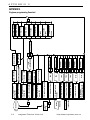
1
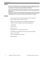
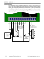
Stand-alone access control
unit with build-in proximity
reader
®
DLK641 Plus
s t a n d - a l o n e
a c c e s s
c o n t r o l
u n i t
This manual covers installation, programming and utilization of DLK-641Plus standalone access control unit. Read this manual carefully prior to installing and programming of the unit.
Design Change Disclaimer
Due to design changes and product improvements information in this manual is subject
to change without notice. ITV reserves the right to change product design any time,
which may subsequently affect the contents of this manual.
ITV assumes no responsibility for any errors that may appear in this manual. ITV will
make every reasonable effort to ensure that this Installation/Programming Manual is
up to date and corresponds with unit you purchase.
Reproduction Disclaimer
All rights on this document are preserved by Integrated Technical Vision Ltd. Copying,
printing and any other kind of reproduction of the document or its part without permission of Integrated Technical Vision Ltd is prohibited.
Trademarks
ITV® is registered trademark of Integrated Technical Vision Ltd.
Training and technical support
Integrated Technical Vision Ltd performs training on the installation, programming and
idolization of DLK-641Plus stand-alone access control unit. For additional information
about the training and discussing of your particular requirements to the unit please
contact our personnel by the phone numbers below.
For the personnel intended for sales and installation of DLK-641Plus stand-alone
access control unit on permanent basis is recommended to pass the training in Integrated Technical Vision Ltd.
Technical support for all products of Integrated Technical Vision Ltd can be obtained
during business hours by the phones:
+380 (0) 44 248 65 88
+380 (0) 44 248 65 89
+380 (0) 44 248 65 90
This support assumes the calls of trained specialists. End users must apply to their
dealers or installers before calling us.
All information is available on our web site www.itvsystems.com.ua
2
Integrated Technical Vision Ltd
http://www.itvsystems.com.ua
Contents
Preface ..................................................................................................
Benefits ..................................................................................................
Features ...............................................................................................
Specifications ........................................................................................
Electrical ..............................................................................................
Mechanical ..........................................................................................
Environmental .....................................................................................
Operation ...............................................................................................
Construction ........................................................................................
Mounting ..............................................................................................
Mounting and wiring of external reader ..............................................
Request to Exit (RTE) Button ..............................................................
Door sensor ........................................................................................
Electric locks and door strikes ............................................................
Sirens and Bells ..................................................................................
Alarm output ........................................................................................
Code Entering (Proximity card using) .................................................
Codes ..................................................................................................
Duress Code .......................................................................................
LEDs ....................................................................................................
Entry time .............................................................................................
"Open door" mode ...............................................................................
Control Panel Operation .......................................................................
Programming ........................................................................................
Default factory settings ........................................................................
Default times .......................................................................................
Settings displaying ..............................................................................
Hardware reset to factory defaults ......................................................
Engineer code programming mode ...................................................
Master code programming mode .........................................................
User code settings editing ..................................................................
Access level change ...........................................................................
User code change ...............................................................................
User code view ....................................................................................
Changing code with the user code .....................................................
APPENDIX 1 ..........................................................................................
Simple Access Control - one door ......................................................
Simple Access Control - two doors ....................................................
Card + PIN access control ..................................................................
Use in alarm system ...........................................................................
APPENDIX 2 ..........................................................................................
Limited Warranty ...................................................................................
http://www.itvsystems.com.ua
4
4
5
5
5
5
5
6
6
8
9
9
9
10
10
10
11
11
12
12
12
12
12
13
13
14
14
14
15
20
20
20
20
20
21
22
22
24
25
26
28
37
Integrated Technical Vision Ltd
3
P r e f a c e
Preface
DLK-641Plus stand-alone access control unit is a basis for completely autonomous
access control system within one door. Being technologically sophisticated, it is quick
and simple to use, as well as compact and flexible in application.
You can open a door introducing your access code or using unique proximity tag. A
tag is a small, self-contained, automatic identification device, usually in shape of key
trinket or card.
DLK641Plus consists of a compact surface mounted access control unit and internal
stand-alone reader, that can be expanded with additional vandal-proof reader for
outdoor applications. The system can be programmed using its own keypad.
Benefits
-
4
Proximity reader and control system integrated into one compact unit
Easy to install, low profile, surface mounted
Rugged, vandal resistant reader can be attached for outdoor use
Programming via own keypad or computer-based programmer
1 master code
1 engineer code
253 users' codes
Read range of 10 cm with internal RF antenna
Three LEDs for visual indication and buzzer for audio annunciation
Power +10 to +15 VDC
Power consumption 50 mA to 130 mA
Anti-tamper alarm
Integrated Technical Vision Ltd
http://www.itvsystems.com.ua
F e a t u r e s
Features
–
Fully programmable from built-in keypad
–
Additional Proximity reader
–
Sealed housing
–
Read range up to 15 cm
–
Bi-color LEDs
–
Built-in buzzer
–
Up to 50 m mounting distance
–
Utilizes proximity technology or keypad codes 4-10 digits long
–
One Master code
–
One Engineer code
–
253 user codes
–
Additional duress code for each user code
–
Two access levels
–
Two relays
–
Alarm output
–
Door sensor
–
RTE button
–
Tamper
–
Three LEDs
Specifications
Electrical
–
Voltage
–
Power consumption
–
–
Standby
–
Maximal
10 … 15 V
50 mA
130 mA
Contact Rating
–
Relay
5A @ 24 V
–
Alarm Output
OC, 60 mA @ 24V
Mechanical
–
Weight
250 grams
–
Dimensions
155 x 95 x 32 mm
Environmental
–
Temperature
0… +55 C°
–
Relative humidity
80% @ +35 C° no condensation
http://www.itvsystems.com.ua
Integrated Technical Vision Ltd
5
O p e r a t i o n
Operation
Construction
DLK-641Plus stand-alone access control unit is shown on Figure 1
1
2
3
4
a)
7
5
I/O BK RD BL WH YW GN OR
X2
8
J1
FACTORY
SETTING
6
+12V GND RTE DC GND
SAB
ALM CM1NC1NO1 CM2NC2 NO2
b)
1 - LED1,
2 - LED2,
3 - LED3,
4 - built-in keypad,
5 - blank end cover,
6 - control unit PCB,
7 - built-in reader PCB,
8 - front cover
6
Integrated Technical Vision Ltd
http://www.itvsystems.com.ua
O p e r a t i o n
Terminals layout on the mainboard is shown on Figure 2
External reader
Built-in reader PCB
X2
FACTORY
SETTING
I/O BK RD BL WH YW GN OR
+12V GND RTE DC GND SAB ALMCM1NC1 NO1CM2NC2NO2
Mainboard
Tamper
Alarm output
Eelectric door
locks and
strikes
Door sensor
RTE Button
Power supply +12 V
Figure 2
http://www.itvsystems.com.ua
Integrated Technical Vision Ltd
7
O p e r a t i o n
Terminals assignment:
Marking
Description
Position
+12V, GND
RTE, GND
DC, GND
X1
X1
X1
Power supply connection terminals
RTE button connection terminal
Door sensor connection terminal
Tamper terminals - to be connected to alarm
control unit
Alarm output - to be connected to alarm control
unit
Normally opened, Common and Normally
closed contacts of the second relay
Normally opened, Common and Normally
closed contacts of the first relay
SAB
X1
A LM
X1
NO2, CM2, NC2
X1
NO1, CM1, NC1
X1
X2
X2
Built-in reader connector
I/O
BK
RD
BL
WH
YW
GN
OR
X3
X3
X3
X3
X3
X3
X3
X3
Not connected - reserved
Black wire of the external reader
Red wire of the external reader
Blue wire of the external reader
White wire of the external reader
Yellow wire of the external reader
Green wire of the external reader
Orange wire of the external reader
Mounting
DLK-641Plus stand-alone access control unit is to be mounted indoors at 85% relative
humidity.
Mounting on metal surfaces decreases reading range.
Do not mount the panel and lay out wires close to power electric wiring or any other
source of strong RFI interference.
DLK641Plus mounting succession description:
–
Release the screw in the bottom of the cover pos a) on Figure 3
–
Slightly pull the bottom side of the cover (pos b) on Figure 3) and take it down
–
Disconnect reader PCB from the baseplate (connector X3)
–
Thoroughly release fixing tabs and take the base plate off (pos c) on Figure3)
– Mark the position of fixing holes on a wall, using back plate as a pattern (pos d)
on Figure 3)
8
–
Drill fixing holes of appropriate depth with 6 mm drill
–
Pull wiring through the holes on back plate and secure it with supplied screws
–
Fix firmly the front cover
–
Connect wires
–
Connect built-in reader PCB to baseplate with a screw.
Integrated Technical Vision Ltd
http://www.itvsystems.com.ua
O p e r a t i o n
a)
b)
c)
d)
Mounting
holes
Reader
Connector
X2
J1
FACTORY
SETTING
I/O BK RD BL W H YW GN OR
+12V GND BUT DR GND
SAB ALM CM 1NC1 NO1CM 2NC1 NO1
Wiring
holes
5...10mm
Fixing tabs
Mounting and wiring of external reader
orange
white
yellow
green
red
blue
black
external reader
I/O BK RD BLWHYW GN OR
Figure 4
DLK-641Plus stand-alone access control unit has built-in proximity reader and keypad. You can also connect external reader
with specific interface.
It is recommended to install external reader on a wall not
far from door approximately on height of a lock. Make a small
deepening or opening beneath external reader for cabling. Cable length can be expanded up to 50 m by 7 wire non-shielded
AWG24 cable.
Avoid conductors confusing while expanding cable length.
It is not recommended to install external reader on metal
surface as it decreases reading distance.
Request to Exit (RTE) Button
Request to Exit Button is to be used in case of door pass supervised only in one
direction. You can open a door for exit with RTE button depressing.
You can also use RTE button for remote manual door opening - guard or secretary can
open a door for instance.
Direct opening by engaging of electric lock or door strike will cause alarm mode
switch.
Depressing of RTE button is identical to
introducing user code #2. All settings
of RTE button are to be programmed
for user code #2. Deletion of user code
#2 causes alarm output activation.
If RTE button is pressed more than for
8 seconds, alarm output is activated .
Door sensor
DLK-641Plus determines door status by
means of door sensor. If you do not
GND RTE DC GND
Door
sensor
SAB ALMCM1
RTE
Button
Figure 5
http://www.itvsystems.com.ua
Integrated Technical Vision Ltd
9
O p e r a t i o n
use door sensor, the unit cannot detect neither door forcing nor door left opened for
a long time.
Wiring of door sensor and RTE button is shown on Figure 5. Door sensor has normally
closed contacts, while RTE button must have normally open contacts.
It is advisable to equip the door with mechanical door closer.
Electric locks and door strikes
The unit has two relays with normally opened and normally closed contacts for
energizing or de-energizing electric locks, door strikes etc.
Relays are activated after valid code entry. Relays can work in trigger mode (program
relay time for 0 sec) - in this case
relay changes its state on each
valid code entering. Relays can
also be activated for programmed
time from one to 254 sec. You can
GND SAB ALM CM1 NC1 NO1 CM2 NC2 NO2
program relay activation time for
each code individually.
Relay contact commutation is 5 A
+Uпит
@ 24 Volts. Commutation of the
inductive load, electric lock for inLock 2
stance, causes high energy electric impulse induced through relay
contacts. To save contacts from
damage, protect them with diode,
connected in reverse to current
Lock 1
supply of the coil.
Note the fact, that some cheap
Figure 6
electric door strikes are not intended for being energizing for prolonged time. Program relay time as short as possible to avoid door strike coil overheating.
Read this installation manual carefully before connecting lock or door strike or programming its operation parameters. Make sure that your power supply is powerful
enough to drive lock or door strike. If lock or door strike requires 12 volts power, you
can power it in parallel with DLK-641Plus stand-alone access control unit, otherwise
you have to install additional power supply for locking device.
It is recommended to consult with the manufacturer of your locking device before its
installation.
Sirens and Bells
Some sirens require polarity observing.
Often Electric bells are the inductive load for power supply. Connecting bells observe
warning about the inductive load above.
Alarm output
Alarm output is an open collector transistor output. It grounds during activating. You
can utilize alarm output connecting it to alarm control panel or sounder with operation
current less than 60 mA.
If door contact is connected to DC terminal, alarm output will activate any time door is
10
Integrated Technical Vision Ltd
http://www.itvsystems.com.ua
O p e r a t i o n
opened, except for time, when access is granted. Alarm output activates for programmed alarm time from 1 to 254 seconds. If alarm time is programmed for 0 seconds, alarm output will never activate. If alarm time is programmed for 255 seconds,
alarm output is activated until "Chief" or "Engineer" code is entered. Alarm time can be
programmed by means of "Engineer" code.
Code Entering (Proximity card using)
Code is introduced by sequential key depressing on keypad. Length of code can vary
from four to ten digits. Code entry is followed by pressing of [#] button. Each key
pressing is accompanied by sound of internal buzzer. Valid code is signalled by one
long sound. Entering of invalid code is accompanied by one long and two short
sounds.
If invalid code is entered (or card passed) three times, DLK-641Plus stand-alone
access control unit blocks itself for programmed time. Blocking is indicated by rapid
blinking of red LED 2.
You can cancel entered digits succession with [*] button pressing in case of mistake.
If no key is pressed during 40 seconds, all previously entered digits are discarded and
unit switches into standby mode.
Card passing is equivalent to code entering.
Codes
Several types of codes (cards) are intended for unit control.
Code #00 -is Engineer code. It allows:
-
Engineer Code programming,
-
Master Code programming,
-
Relay operation modes and door time programming (individually for each user
code),
-
Alarm output time programming,
-
Keypad blocking time programming,
-
Return to factory settings.
Code #01 - is Master code. It allows:
-
Master Code programming,
-
User codes and their access level programming,
Codes #02 - 255 - are user codes. It is allowable to:
-
Drive relays
-
Switch day/night modes
- Change code, if permitted
Entering of user code #2 is identical to RTE button pressing. Changing of settings of
user Code #2 causes changing of RTE button settings. Removal of the user code #2
causes alarm output activation at depressing RTE button.
For each user code you can program:
-
Access level from 1 to 4, defines access rights (programmed by "Master" code)
-
Code options - choose relays to drive, relay time, door time (programmed by
"Engineer" code)
http://www.itvsystems.com.ua
Integrated Technical Vision Ltd
11
O p e r a t i o n
Duress Code
Each user, besides his regular code, has an additional duress code, independently on
user code access level and options. When this code is entered, DLK-641Plus standalone access control unit grants access accordingly to user code access level and
options and moreover alarm output switches on.
Cardholders have no duress code.
Duress code differs from user code in last digit per one. For instance, if user code is
[1][2][3][4], then duress code for this user is [1][2][3][5].
If user code ends with '9', then duress code ends with '0'. For instance, if user code
is [1][0][0][9], then duress code for this user is [1][0][0][0].
LEDs
There are three LEDs on front cover of DLK-641Plus stand-alone access control unit.
Their functioning is described below.
Main mode
LED 1 (Orange) indicates operation mode
LED 2 (Bi-color, Red and Green): Red - indicates I/O output status, Green - Relay 1
status
LED 3 (Green) - Relay 2 status
Programming mode
LED 2 (Bi-color, Red and Green): indicates access levels and user code options, and
numeric values of unit settings.
LED 3 (Green) - indicates access levels and user code options.
Entry time
Entry time starts after relay activation.
First break and closing of door sensor stops entry time. Warning signal sounds, if door
is opened for five seconds before entry time ending. In this case you should close the
door or enter code once more to start entry time again. Otherwise, alarm output will be
activated.
Door time is programmed by means of an "Engineer" code. Valid values are 0-253
seconds.
"Open door" mode
After code with 254 sec Entry time entering, a door will not be supervised for unlimited
time until it is closed.
Lockout Mode
If invalid code is entered or card passed three times, the unit locks out for programmed
time. Lockout time can be programmed from 1 to 255 seconds. Programming this value
to 0 disables lockout mode.
12
Integrated Technical Vision Ltd
http://www.itvsystems.com.ua
C o n t r o l
P a n e l
O p e r a t i o n
Control Panel Operation
DLK-641Plus can operate in one of the modes:
-
Main mode
-
Restricted mode
-
User code programming
-
Programming with "Engineer" code
-
Programming with "Master" code
-
Lockout mode
LED 1 lights (red) continuously in main mode . The unit performs actions, programmed
for introduced code or card presented in this mode. These actions are: Relay 1
activation, Relay 2 activation, activation of both relays or opportunity to choose relay
for activation.
Restricted mode of the unit is indicated by "slow" blinks of LED 2. In this mode only
cards with access level 2 are valid.
To switch the unit into restricted mode enter code or present a card without control
over any relay permission (see "Engineer programming mode"). This code or card
should have access level 2, otherwise the code will be able to switch restricted mode
on, but unable to switch the unit into main mode.
If duress code is entered, DLK-641Plus performs actions according to user code
access level and options and engages alarm output for programmed time. Alarm output
switches on immediately after duress code introduction.
If user code, programmed for choice between Relay 1 and Relay 2 activation is
entered, LEDs 2 (green) and 3 will flash. To choose Relay 1 or Relay 2 press key [1]
or key [2] accordingly.
If there are no keystrokes for 40 seconds, the unit switches to main mode automatically.
Program desired settings and codes before utilizing the unit.
Programming
During programming DLK-641Plus stand-alone access control unit ignores break/
opening of RTE button. Supervision of door sensor lasts as usual.
Default factory settings
After first switching on and after return to default factory settings DLK-641Plus
works in main mode with the following settings:
-
Alarm output time
10 sec
-
Lockout time
40 sec
-
Engineer code
1234
-
Master code
5678
-
User code
#2
[A][A][A][A]
-
Code drives
Relay2
-
Relay time
3 sec
http://www.itvsystems.com.ua
Integrated Technical Vision Ltd
13
P r o g r a m m i n g
-
Door time
-
Access level
15 sec
3
-
Without external reader
-
Default Relay 1 time
3 sec
-
Default Relay 2 time
3 sec
-
Default door time
20 sec
-
Reader mode
internal only
- Modulation type
ASK
Factory setting of user code 2 - [A][A][A][A] - consists of hexadecimal digits 'A'. This
is made intensionally to avoid code entering on keypad after factory defaults
settings, but RTE button should be used.
Default times
There are tree "default" times - Relay 1 Default time, Relay 2 Default time and Door
Default time, which are made for convenience of programming.
You can refer to these values while programming parameters of user codes. In this
case changing only "default" time, you will change appropriate values for all codes,
referring to it.
For instance if you enroll new user code - its relay time will be automatically set to 255.
It means, that as value of relay time for this code the default relay time will be used. If
you set the value of relay time to 255 for several codes it means that you use default
relay time for all of these codes. Modifying Default Relay Time, you change time of
relay activation for all these codes.
Settings displaying
Numeric values of settings are displayed by built-in buzzer and LED 2, see Figure 1.
Nonzero value is displayed as number of short beeps and LED 2 blinks. Digits are
separated by an interval.
For instance, number 235 will be displayed as follows:
2 blinks of LED 2 - 2 beeps, interval, 3 blinks of LED 2 - 3 beeps, interval, 5 blinks of LED
2 - 5 beeps.
Digit '0' is displayed as one long sound and LED 2 flash. For instance, number 040 is
displayed as follows: LED 2 lights + long sound, interval, 4 blinks of LED 2 + 4 beeps,
interval, LED 2 lights + long sound.
Parameters are displayed with LED2 and LED3.
Green light of LED 2 means 'YES'.
Hardware reset to factory defaults
1. Cut off the power
2. Short jumper J1
Reader
Connector
X2
J1
FACTORY
DEFAULT
To reset DLK-641Plus to the factory defaults perform the following actions:
3. Power on the unit. Buzzer will sound three
long beeps, then several short beeps accompanied by LED 1 blinking. Parameters are set to
14
Integrated Technical Vision Ltd
http://www.itvsystems.com.ua
P r o g r a m m i n g
factory defaults and controller is in "Engineer" programming mode now.
After resetting to factory defaults all user codes will be deleted!
4. Take off jumper J1 with power on. Program desired settings.
Engineer code programming mode
Enter [Engineer code] [#], factory setting - [1] [2] [3] [4] to start Engineer code
programming mode. Beeper will sound several times accompanied with LED 3 and
green LED 2 blinks. LED 1 lights during programming.
Engineer code can be changed as it is described in "Changing code with user code"
part below.
Engineer code programming mode is described in APPENDIX 2 "Engineer code programming flowchart".
After Engineer code programming mode engaging you acquire following possibilities:
Master code programming.
Enter [0][#], then enter new [Master code][#] and confirm it: [Master code][#].
New code will be accepted if it differs from any enrolled user code and duress codes.
Example To change Master code to 7777 in Engineer code programming mode enter [0][#], then
[7] [7] [7] [7] [#] and once more [7] [7] [7] [7] [#].
Enrolling of user code
Enter [1][#]. DLK-641Plus displays number of first unused user code with buzzer and
LED 2 indications. Enter [User Code][#]. After this you can change code settings or
turn to Engineer programming mode by pressing [#].
Default settings for new code are:
Code drives Relay 1
Relay Time - 255 (default Relay times)
Door Time - 255 (default door time)
Access level - 3
To view or change settings press appropriate key (see Table 1)
To exit user code settings editing mode press [#] button.
User code settings' editing
Enter [2][#]. Then enter [number] of user code OR [User Code] OR pass proximity
card and press [#]. View relay settings for this user code after definite button pressing (see Table 1).
Press appropriate key for parameters change (see Table 1).
"Default" value of relay time is used if you need to set equal times for many user
codes. If you are using "default" times, changing of this values causes changes of
times for all user codes, referred to them.
http://www.itvsystems.com.ua
Integrated Technical Vision Ltd
15
P r o g r a m m i n g
K ey
Function
To be follow ed by…
[1]
C ode dri ves Relay1
[2]
C ode dri ves Relay2
[3]
C hoi ce of relay after
C ode
[4]
Relay Ti me Edi ti ng
Relay Ti me value
Entry Ti me Edi ti ng
D oor Ti me value
[5]
R emarks
C ode dri ves Relay 1 i f LED 2
i s ON
C ode dri ves Relay 2 i f LED 3
i s ON
Both LED 2 and LED 3 bli nki ng
for choi ce
'0' - tri gger mode
'255' - "default value"
'0' - no entry ti me
'254' - "opened door" mode
'255' - "default value"
[6],[9],[0] Reserved
[7]
Relay ti me di splay
[8]
Entry ti me di splay
[*]
Ti me di splayed wi th buzzer and
LE D 2
Ti me di splayed wi th buzzer and
LE D 2
Press [1] to swi tch
See Table 2 for LED s
LE D 2
correspondence to access
Press [2] to swi tch
levels, [#] for exi t
LE D 3
You can edit access level of code after pressing of [*] button, see Table 2.
Swi tch to Access level
setti ng
Table 2
A cce ss
level
1
LE D
1
OFF
LE D
2
OFF
User Code
is
Inert
User can change
own code
NO
2
OFF
ON
Active
YES
3
4
ON
ON
OFF
ON
Active
Active
NO
YES
Code is valid
in mode
N/A
Main &
Restricted
Main (only)
Main (only)
Press [#] to exit access level editing.
Press [#] to exit editing of user code settings.
Example To program new user code [1] [9] [7] [5], driving Relay 2, with 19 sec Relay Time , Door
Time= 55 sec and lockout OFF, perform the following actions:
Enter [Engineer code] [#]. Buzzer sounds several beeps, which are accompanied
with LEDs 2 and 3 blinking. During programming LED 1 blinks red.
Enter [1][#]. Unused user code will be displayed with buzzer and LED 2. If all codes
are occupied, unit automatically returns to Engineer code programming.
Enter user code: [1] [9] [7] [5] [#]. If code is accepted, buzzer sounds long beep. If an
error occurred - one continuous and two short beeps would be heard. By default,
new code has following settings:
16
Integrated Technical Vision Ltd
http://www.itvsystems.com.ua
P r o g r a m m i n g
Code drives Relay 1
Relay Time - 255 (default Relay time)
Door Time - 255 (default door time)
Access level - 3
Press key [1]. Green LED 2 switches OFF, that means code does not drive Relay 1.
Press key [2]. LED 3 switches ON, that means code drives Relay 2.
Press key [4]. Buzzer sounds continuous beep, that means unit is ready for Relay
Time editing.
Press keys [1][9][#]. Buzzer sounds continuous beep, that means unit has accepted
new value of Relay Time.
Press key [5]. Buzzer sounds continuous beep, that means unit is ready for Entry
Time editing.
Press keys [5][5][#]. Buzzer sounds continuous beep, that means unit has accepted
new value of Entry Time.
Press key [#] to return to Engineer code programming mode.
Enter [1][2][#], Buzzer sounds continuous beep and then displays previously programmed Lockout Time.
Press [*], continuous beep sounds - unit is ready for Lockout Time editing.
Press [0][#], continuous beep sounds - changes are accepted.
Press [#], continuous beep sounds and unit quits Engineer programming.
User code viewing and editing
Press [3][#], then [number][#] of user code OR [user code][#]. DLK-641Plus
stand-alone access control unit displays user code. Pressing of [#] will return you to
Engineer programming, pressing of [*] allows to enter new user code.
Example If you want to change user code #3 to [0] [6] [1] [1] [7] [5] being in Engineer code
programming mode
Press [3][#], DLK-641Plus stand-alone access control unit displays user code.
Press [*], then [0] [6] [1] [1] [7] [5][#].
User code deletion
Enter [4][#] then [number][#] of user code OR [user code][#].
Example If you want to delete user code #17 press [4][#] then [1][7][#].
Reset to factory defaults
Enter [5][#], then [Engineer code][#].
After performing of this operation all previously programmed user codes are deleted
and Engineer code, Chief code and code #2 are programmed according to factory
defaults.
Example If Engineer code is [1] [9] [8] [8], and you want to reset DLK-641Plus stand-alone
access control unit to factory defaults, press [5] [#]. Buzzer utters nine sound signals. Enter Engineer code: [1] [9] [8] [8].
http://www.itvsystems.com.ua
Integrated Technical Vision Ltd
17
P r o g r a m m i n g
Batch enrollment
Enter [1][0][#] for batch enrollment. On opposite to [1][#] command, during batch
enrollment default settings are given to code after its entry; unit does not suggest
editing of settings. Instead of that unit seeks for the next unused code number.
If you use proximity card record fix its number and mark to what person it is passed.
In case of card loss, you can delete it only by its number. If you do not know the
number of lost card, you will have to reset the unit and repeat enrollment of all cads.
Example Enter [1] [0] [#] in Engineer code programming mode and sequentially present all
cards to enroll 50 proximity cards.
If enrolled card is already present during single ([0][1] [#] command) and batch ([1] [0]
[#] command) enrollment, unit utters error signal, but does not return to Engineer's
code programming mode.
It is especially convenient in batch enrollment mode - if you pass already enrolled card
you hear error signal.
Unit quits batch enrollment only after memory overflow, with pressing of [#] key or
automatically after 40 seconds of non-activity.
Alarm Time setting
Enter [1] [1] [#]. Unit displays value of Alarm Time with buzzer and LED 2. Press [#]
to exit Alarm Time setting. In order to enter new value press [*] [new Alarm Time
value] [#].
If value of Alarm Time is set to 0 seconds, alarm output will not be activated. If value
of alarm time is set to 255 seconds, alarm output will be activated until Master or
Engineer code is enter ed.
Example If you want to enter new value of Lockout Time with buzzer and LED 2. If you want
to exit Lockout Time setting press [#]. In order to enter new value press [*] [new
Lockout Time value] [#].
If value of Lockout Time is set to 0 seconds, Lockout will not be active.
Example If you want to enter new Lockout Time value of 80 seconds press [1] [2] [#] in
Engineer programming mode. Unit displays current value of Lockout Time with buzzer
and LED 2. Press [*] [8] [0] [#].
Relay 1 Default Time setting
Enter [1] [3] [#]. Unit displays value of Relay 1 Time with buzzer and LED 2. If you
want to exit Relay 1 Default Time setting press [#]. In order to enter new value press
[*] [new Relay 1 Default Time value] [#].
Setting Relay 1 Default Time value to 0 turns the relay to trigger mode - entering of
code operating Relay 1 alters the relay status.
Example If you want to set new Relay 1 Default Time value to 10 seconds press [1] [3] [#] in
Engineer programming mode. Unit displays current value of Relay 1Default Time with
buzzer and LED 2 indication. Press [*] [1] [0] [#].
If you want to exit Engineer programming mode press [#].
Relay 2 Default Time setting
Enter [1] [4] [#]. Unit displays value of Relay 2 Default Time with buzzer and LED 2. If
you want to exit Relay 2 Default Time setting press [#]. In order to enter new value
press [*] [new Relay 2 Default Time value] [#].
18
Integrated Technical Vision Ltd
http://www.itvsystems.com.ua
P r o g r a m m i n g
Setting Relay 2 Default Time value to 0 turns the relay to trigger mode - sequential
entering of code operating Relay 2 alters relay status.
Example If you want to set new Relay 2 Default Time value to 9 seconds press [1] [3] [#] in
Engineer programming mode. Unit displays current value of Relay 2 Default Time with
buzzer and LED 3 signals. Press [*] [9] [#].
If you want to quit Engineer programming mode press [#].
Door Time Default setting
Enter [1] [5] [#]. Unit displays value of Default Door Time with buzzer and LED 2. If you
want to exit Door Time Default setting press [#]. To enter new value press [*] [new
Door Time Default value] [#].
Example If you want to set new Default Door Time value to 5 seconds press [1] [5] [#] in
Engineer programming mode. Unit displays current value of Default Door Time with
buzzer and LED 2. Press [*] [5] [#].
Press [#] to exit Engineer programming mode.
Readers functioning control
Enter [1] [6] [#]. Unit displays status of reader functioning settings with buzzer and
LED 2 indication. If you want to exit reader setting programming press [#]. To enter
new setting press [*] [new settings] [#]. You can set following values:
[0] - Only built-in reader active
[1] - Only external reader active
[2] - Built-in reader active in programming modes, external - in main and restricted
[3] - Both readers active in any mode
Factory default is [0].
http://www.itvsystems.com.ua
Integrated Technical Vision Ltd
19
M a s t e r
c o d e
p r o g r a m m i n g
m o d e
Master code programming mode
If you want to switch to Master code programming from main or restricted mode enter
[Master Code][#]. Factory default for Master code is [5] [6] [7] [8][#]. If you want
to change it refer to "Changing code with user code" below. DLK-641Plus stand-alone
access control unit sounds several beeps accompanied by LED 2 and LED 3 blinks.
User code settings editing
Enter [User Code number][#] or [User code][#] or pass a card. Access level of
the code is displayed by LED 2 and LED 3:
A cce ss
level
1
LE D
2
OFF
LE D
3
OFF
User Code
is
Inert
User can change
own code
NO
2
OFF
ON
Active
YES
3
4
ON
ON
OFF
ON
Active
Active
NO
YES
Code is valid
in mode
N/A
Main &
Restricted
Main (only)
Main (only)
Access level change
You can change access level of user code by pressing keys '1' and '2' which are
indicated by Green LED 2 and LED 3 accordingly. New access level will correspond to
LEDs' status as in Table above.
User code change
Press [0]. Unit beeps three times. Enter [New User code] [#] and confirm with [New
User code] [#]. New code will be accepted if it does not coincide with any existing
code or any existing duress code.
User code view
Press [9]. DLK-641Plus stand-alone access control unit displays User Code with
buzzer and LED 2.
If you want to return to Chief programming - press [#].
if you want to exit Master code programming, press [#] again.
If there are no keystrokes during 40 seconds, unit automatically exits programming
mode.
Example You need to change code #4 to [1] [9] [7] [5], make it active, valid in restricted mode
and allowing user to change it.
Enter [MasterCode][#]. DLK-641Plus stand-alone access control unit gives several
beeps accompanied with LED 2 and LED 3 blinks.
Enter Code Number - [4][#], unit gives a long beep. If code #4 is not programmed,
sounds error signal - one long and 2 short beeps. If you want to set access level 2
(code is active, valid in restricted mode and user can change it) make LED 2 OFF and
LED 3 ON by pressing keys [1] and [2] accordingly.
To change a code press [0] key, three short beeps will sound. Enter [1] [9] [7] [5] [#]
- one long beep sounds. If similar user code or duress code exists already, error signal
sounds.
Press [#]. Long sound is given and unit returns to main or restricted mode.
20
Integrated Technical Vision Ltd
http://www.itvsystems.com.ua
M a s t e r
c o d e
p r o g r a m m i n g
m o d e
Changing code with the user code
Any user can change his own code with [*] command, if a code has access level 2
or 4.
Enter [*], DLK-641Plus stand-alone access control unit sounds together with LED 2
blinking. Enter [Old User Code][#], then [New User Code][#] and confirm [New
User Code][#].
New code is accepted, if code changing is allowed, and new code is not identical to
any enrolled user or duress code.
Press [#] to exit code programming.
Chief code and Engineer code are changed in the same way.
If there was no keystrokes during 40 seconds, unit returns to main or restricted mode.
In this case user code does not change.
Example User has code [1] [2] [3] [4] [5] and wants to change code to [4] [3] [2] [1].
In this case access level of the code should be 2 or 4.
Press [*], three beeps sound and LED 2 flashes RED.
Enter old user code [1] [2] [3] [4] [5] [#], long beep sounds. If code has access level
2 or 3 error signal sounds (one long and two short beeps).
Enter new user code - [4] [3] [2] [1] [#], long beep sounds. If the same user code or
duress code exists, error signal sounds and unit quits code programming.
Confirm by entering [4] [3] [2] [1] [#], long beep sounds.
The unit switches to the main mode on successful code changing automatically.
http://www.itvsystems.com.ua
Integrated Technical Vision Ltd
21
A P P E N D I X
1
APPENDIX 1
Examples of DLK-641Plus stand-alone access control unit use
Simple Access Control - one door
DLK-641Plus stand-alone access control unit can be used for access control of a
single room. The wiring is on figure below.
+12V GND RTE DC GND
SAB
ALM CM1 NC1 NO1 CM2 NC2 NO2
Different system
devicesTamper
contacts
connection
Power
supply
+12 V
RTE
Outer alarm
system input
connection
Door
sensor
In this example Relay 2 is used to energize electric lock. Terminals wiring is shown for
lock, locked while being deenergized. Using a lock that is unlocked while being
deenergized, connect it to NC2 terminal. Contacts of Relay 1 you can use to switch
any auxiliary equipment.
22
Integrated Technical Vision Ltd
http://www.itvsystems.com.ua
A P P E N D I X
1
Programming
Change Engineer code to 10011:
Press [*][1][2][3][4][#][1][0][0][1][1][#][1][0][0][1][1][#]
Enter Engineer programming:
Press [1][0][0][1][1][#]
Program Alarm Time: 10 sec
Press [1] [1] [#][*][1][0][#]
Program Lockout Time: 40 sec
Press [1] [2] [#][*][4][0][#]
Program RTE button settings (user code 2):
Press [2] [#][2][#] - Enter user code 2 settings editing
Press [1] until LED 1 switches OFF - Code 2 (RTE) does not drive
Relay 1
Press [2] until LED 2 switches ON - Code 2 (RTE) drives Relay 2
Press [4] [5] [#] - Program Relay Time for Code 2 (RTE) for 5 seconds
Press [5][2] [5] [#] - Program Door Time for Code 2 (RTE) for 25
seconds
Press [#] - Exit RTE button settings (user code 2) editing
Program Default Relay 2 time for 5 seconds:
Press [1] [4] [#][*][5][#]
Program Default Entry time for 25 seconds:
Press [1] [5] [#][*][2][5][#]
Enroll 10 proximity cards in batch mode (all cards will have default settings and refer
to default Relay 1 and Alarm times):
Press [1][0][#], then present all 10 cards
Press [#] to exit batch enrollment
Exit Engineer programming mode:
Press [#]
Do not forget to change Master code:
Press [*][5][6][7][8][#][2][2][3][3][#][2][2][3][3][#] for instance.
http://www.itvsystems.com.ua
Integrated Technical Vision Ltd
23
A P P E N D I X
1
Simple Access Control - two doors
DLK-641Plus stand-alone access control unit can be used for access control of two
rooms. The wiring is on figure below.
+12V GND RTE DC GND
SAB
ALM CM1 NC1 NO1 CM2 NC2 NO2
System devices
tamper
connection
Power
supply
+12 V
Outer system
input connection
RTE
Door
sensor
In this example Relay 1 is used to energize electric lock for the first door and Relay 2
- for the second door. Terminals wiring is shown for the lock, locked while being
deenergized. Using the lock which is unlocked while being deenergized, connect it to
NC1 and NC2 terminals accordingly.
Do not utilize Door Sensor and RTE terminals - just short them.
Some codes can be programmed for access control to the first door, some - to the
second door. If you want to program some codes for access to both doors control,
program their settings for choice of relay, or both doors will open on code introduction.
Programming is similar to previous example, besides, you have to perform the same
steps for Relay 1.
24
Integrated Technical Vision Ltd
http://www.itvsystems.com.ua
A P P E N D I X
1
Card + PIN access control
With DLK-641Plus stand-alone access control unit you can build card + PIN access
control, utilizing Relay 1 and Relay 2 in series (see figure). Each user receives a card
driving Relay 1 and a code driving Relay 2. To unlock a door user must pass a card,
then enter a code. Door cannot be opened with a stolen card, without valid code
entry.
Do not forget to program both relays driving for User #2 to allow using of RTE button.
+12V GND RTE DC GND
SAB
ALM CM1 NC1 NO1 CM2 NC2 NO2
System devices
tamper contacts
connection
Power
supply
+12 V
RTE
http://www.itvsystems.com.ua
Outer system
input connection
Door
sensor
Integrated Technical Vision Ltd
25
A P P E N D I X
1
Use in alarm system
If you have alarm system equipped with alarm panel armed by zone triggering, you
can use DLK-641Plus stand-alone access control unit for setting/unsetting your alarm
system. The wiring for this implementation is shown below. Codes or proximity cards
driving Relay 1 are utilized for access to the premises control and codes or proximity
cards driving Relay 2 are used for setting/unsetting. LED 3, will show set/unset state
of your alarm system.
+12V GND RTE DC GND
SAB
ALM CM1 NC1 NO1 CM2 NC2 NO2
System
setting/unsetting
input connection
System devices
Tamper contacts
connection
Power
supply
+12 V
RTE
26
Door
sensor
Integrated Technical Vision Ltd
Outer system
input
connection
http://www.itvsystems.com.ua
A P P E N D I X
1
Programming tips
Alarm Output Time: 3 sec
Lockout time: 40 seconds
User code #2 (RTE): AAAA, access level 4 (active, change by user prohibited, valid
for main mode) driving Relay 1, Relay Time 10 sec, Door Time 30 sec.
User code #3 (Access code): 3333, access level 4 (active, change by user allowed,
valid for main mode) drives Relay 1, Relay Time 10 sec, Door Time 30 sec.
User code #4 (for main/restricted mode switching): 4444, access level 2 (active,
change by user allowed, valid for restricted mode) does not drive relays, Relay Time
0 sec, Door Time 0 sec.
User code #5 (for arming/disarming): 5555, access level 2 (active, change by user
allowed, valid for restricted mode) drives relay2, Relay Time 0 sec (trigger mode),
Door Time 0 sec.
In this example user should enter User Code #5 for system setting, then enter User
Code #4 to switch unit into restricted mode in order to forbid entrance for user with
User Code #3. Enter User Code #4 in order to switch unit into main mode and User
Code #5 to unset the system. RTE button functions only in main mode.
http://www.itvsystems.com.ua
Integrated Technical Vision Ltd
27
28
Integrated Technical Vision Ltd
introduction
хххххххххх
indication
хххххх
[#]
[engineer
code]
[#]
main mode
05 - reset to factory
preset [#]
time
value
value
16 external reader [#]
17 proximity
identificator type [#]
time
15 default entry time [#]
14 relay2 default time[#]
time
time
12 - keypad lockout
time[#]
13 relay1 default time[#]
time
11 - alarm signal time[#]
[#]
[*]
[#]
[*]
http://www.itvsystems.com.ua
[#]
[*]
[#]
[*]
[#]
[*]
[#]
[*]
[#]
[*]
[engineer code [#]
04 - code removal [#]
10 - batch enrollment [#]
[code number] [#]
or [code]
[#]
03 - code editing [#]
[code number][#]
or [code]
[#]
[value] [#]
[value] [#]
code
introduction
[value] [#]
[value] [#]
[value] [#]
[value] [#]
[#]
[*]
[new code] [#]
[new code] [#]
[value] [#]
vacant code number
[new code] [#]
[code number][#]
or [code]
[#]
02 - code parameters
editing [#]
01 - add new code[#]
00 - master code
change[#]
[новыйкод] [#]
* code options
editing
08 entry time
display
07 relay time
display
06 future used
05 entry time
04 relay time
03 relay choice
02 relay 2 control
01 relay 1 control
[#]
A P P E N D I X
2
APPENDIX 2
Engineer programming flowchart
A P P E N D I X
3
APPENDIX 3
Programming worksheets
Access levels (for reference)
A cce ss
level
1
LE D
2
OFF
LE D
3
OFF
User Code
is
Inert
User can change
own code
NO
2
OFF
ON
Active
YES
3
4
ON
ON
OFF
ON
Active
Active
NO
YES
Code is valid
in mode
N/A
Main &
Restricted
Main (only)
Main (only)
Time settings
Setting
Value
Alarm Time
Lockout Time
Relay 1 Time Default
Relay 2 Time Default
Default Entry Time
Factory defaults
1 0 se c
4 0 se c
3 se c
3 se c
2 0 se c
Reader operation mode setting [1][6][#]
Setting
0 - Built-in reader only
1 - External reader only
2 - Built-in readrer active in
programming modes,
external - in main and
restricted
3 - Both readers active in
any mode
http://www.itvsystems.com.ua
Value
Factory defaults
0 Built-in reader only
Integrated Technical Vision Ltd
29
C ode #
User personalities Access level Relay 1
Exam ple John Smith
00
01
02
03
04
05
07
08
09
10
11
12
13
14
15
16
17
18
19
20
21
22
23
24
25
26
27
28
29
30
32
33
34
35
36
37
38
39
40
30
2
+
Relay 2
Relay
Time
Door Time
-
10
25
Engineer Code
Chief Code
RTE Button
Integrated Technical Vision Ltd
http://www.itvsystems.com.ua
C ode #
User personalities
Access
level
Relay 1
Relay 2
Relay
Time
Door Time
41
42
43
44
45
46
47
48
49
50
51
52
53
54
55
56
57
58
59
60
61
62
63
64
65
66
67
68
69
70
71
72
73
74
75
76
77
78
79
80
http://www.itvsystems.com.ua
Integrated Technical Vision Ltd
31
C ode #
User personalities
Access
level
Relay 1
Relay 2
Relay
Time
Door Time
81
82
83
84
85
86
87
88
89
90
91
92
93
94
95
96
97
98
99
100
101
102
103
104
105
106
107
108
109
110
111
112
113
114
115
116
117
118
119
120
32
Integrated Technical Vision Ltd
http://www.itvsystems.com.ua
C ode #
User personalities
Access
level
Relay 1
Relay 2
Relay
Time
Door Time
121
122
123
124
125
126
127
128
129
130
131
132
133
134
135
136
137
138
139
140
141
142
143
144
145
146
147
148
149
150
151
152
153
154
155
156
157
158
159
160
http://www.itvsystems.com.ua
Integrated Technical Vision Ltd
33
C ode #
User personalities
Access
level
Relay 1
Relay 2
Relay
Time
Door Time
161
162
163
164
165
166
167
168
169
170
171
172
173
174
175
176
177
178
179
180
181
182
183
184
185
186
187
188
189
190
191
192
193
194
195
196
197
198
199
200
34
Integrated Technical Vision Ltd
http://www.itvsystems.com.ua
C ode #
User personalities
Access
level
Relay 1
Relay 2
Relay
Time
Door Time
201
202
203
204
205
206
207
208
209
210
211
212
213
214
215
216
217
218
219
220
221
222
223
224
225
226
227
228
229
230
231
232
233
234
235
236
237
238
239
240
http://www.itvsystems.com.ua
Integrated Technical Vision Ltd
35
C ode #
User personalities
Access
level
Relay 1
Relay 2
Relay
Time
Door Time
241
242
243
244
245
246
247
248
249
250
251
252
253
254
255
36
Integrated Technical Vision Ltd
http://www.itvsystems.com.ua
L i m i t e d
W a r r a n t y
Limited Warranty
Integrated Technical Vision Ltd. warrants that for a period of eighteen months from the
date of purchase, the product shall be free of defect in materials and workmanship
under normal use and that in fulfillment of any breach of such warranty, Integrated
Technical Vision ltd. shall, at its option, repair or replace the defective equipment upon
return of the equipment to its repair depot. This warranty applies only to defects in
parts and workmanship and not damaged incurred in shipping or handing, or damaged
due to causes beyond the control of Integrated Technical Vision Ltd. such as lightning,
excessive voltage, mechanical shock, water damage, or damage arising out of abuse,
alteration or improper application of the equipment.
The foregoing warranty shall apply only to the original buyer, and is and shall be lieu
of any and all other warranties, whether expressed or implied and of all other obligations or liabilities on the part of Integrated Technical Vision Ltd. This warranty contains
the entire warranty. Integrated Technical Vision Ltd. neither assumes, nor authorizes
any other person purporting to act on its behalf to modify or to change this warranty,
nor to assume for it any warranty or liability concerning this product.
In no event shall Integrated Technical Vision Ltd. be liable for any direct, indirect or
consequential damages. Loss of anticipated profits, loss of time or any other losses
incurred by the buyer in connection with the purchase, installation or operation or
failure of this product.
http://www.itvsystems.com.ua
Integrated Technical Vision Ltd
37
38
Integrated Technical Vision Ltd
http://www.itvsystems.com.ua
http://www.itvsystems.com.ua
Integrated Technical Vision Ltd
39
010403
40
Integrated Technical Vision Ltd
http://www.itvsystems.com.ua