1
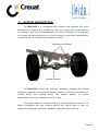
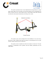
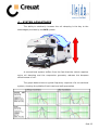
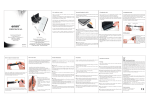
CREUAT RCS
(Roll Control System)
By
Lleida-Tracció
PRODUCT MANUAL
1 de 12
INDEX
First considerations ..................................................................... 3
Delivered components ................................................................. 3
Contacts .................................................................................... 3
1.- INTRODUCTION ..................................................................... 4
2 – ANTECEDENTS. ..................................................................... 5
3 – SYSTEM DESCRIPTION. .......................................................... 6
4 – SYSTEM ADVANTAGES. .......................................................... 8
5.- SYSTEM INSTALLATION GUIDELINES.......................................10
6.- MAINTENANCE AND REPAIR ...................................................11
6.1 – Check points...................................................................11
6.2 – Repair............................................................................12
6.3 – Revision and maintenance intervals ...................................12
2 de 12
First considerations
Ø Before installing the kit, please read carefully this manual.
Ø Installation,
maintenance
and
repair
operations
that
involve
disassembling or manipulating the system can only be performed by
certified CREUAT centers such as LLEIDA TRACCIÓ
Ø The suspension is a vital element for all vehicles safety, it is
paramount to relay on professional service teams to perform the
system installation and periodic revisions.
Delivered components
The RCS KIT is delivered with the components as listed below:
Ø Installation Manual (copy for the Shop)
Ø User Manual (copy for the end user)
Ø The CREUAT system that includes one Central Device connected to 2
hydraulic actuators by means hydraulic hoses
Contacts
OFFICIAL TECHNICAL SERVICE
CREUAT, S. L.
LLEIDA TRACCIÓ TECHNOLOGY, S. L.
c/Montseny, 16
08956 La Palma de Cervelló
c/Sicoris, 20
25001 Lleida
Tl: 936 721 221
Fax: 936 721 053
Tl: 973 204 193
Fax: 973 213 651
Mail: [email protected]
Web: www.creuat.com
Mail: [email protected]
Web: www.lleidatracciotechnology.com
3 de 12
1. - INTRODUCTION
This Installation Manual is aimed to the personnel that does the
installation of the RCS KIT to a vehicle.
The purpose of this manual is to provide the installation guidance,
understand the operating instructions, as well as the necessary information
related to the basic maintenance and failure detection. This document will
describe the system layout, how to install it and do the maintenance.
The RCS KIT replaces the shock absorbers with two actuators
interconnected through a central device. The interconnection is made of
flexible hoses that easy the installation process and deal with the small
actuator movements caused by the suspension movements.
Once installed, the RCS KIT is immediately operative and requires no
further manipulations.
We are sure that you will enjoy driving your vehicle right after the
suspension system has been installed on it.
4 de 12
2 – ANTECEDENTS
Motorhome and ambulance manufacturers often use chassis from light
trucks to build them on, with some adaptations due to the needs of the
market. These chassis normally incorporate leaf springs and shock absorbers
in the rear axle, which were neither designed for the high center of masses
of these vehicles, nor to provide comfort for passengers. It is a fact that
customers often replace it with air suspension or more sophisticated systems
in pursue of better comfort and driving safety.
In general, a suspension designed for the transportation of goods
rarely takes into consideration any comfort parameter that relate to the
transportation of persons. The most widely adopted solution is a rigid axle
that always reduces the dampers effectiveness to control roll. Often these
vehicles are delivered with a rather stiff rear suspension to cope with large
variations of load and, without much subtlety, to covertly fix an inherent
instability component.
Motorhomes and ambulances are characterized by a high center of
masses and large roll inertia. This makes them prone to roll over and quite
unstable at moderate driving speed. So far the only solution is to make it
stiffer to reduce the roll movements, which in turn destroys any comfort that
was left. The alternative to maintain a bare minimum comfort would impair
stability and create an important safety issue.
The RCS KIT provides different damping rates for roll and vertical
movements, so it can solve the problem of providing the right roll damping
while keeping soft vertical suspension rates and maintain the comfort level.
The RCS KIT also provides different bound and rebound damping
rates. This helps to increase the comfort perception and reduces the pitch
movements on braking.
5 de 12
3 – SYSTEM DESCRIPTION
The RCS KIT is a hydropneumatic system that replaces the shock
absorbers in a vehicle axle, usually the rear one. It does not include sensors
or actuators, and reacts instantaneously to wheel movements. It is designed
to provide separate response to roll and vertical movements, appropriately
controlling both movements with distinct inertias.
Hydraulic cylinders
Central device
The RCS KIT mounts two hydraulic actuators replacing the former
dampers, attached to the existing damper supports. They are connected to a
central
device
with
flexible
hoses.
The
system
requires
no
further
manipulation and once installed is ready to use.
The system does not interfere with any other suspension element. It is
totally compatible with the existing antiroll bar, spring leafs or even air
suspension bags that have been added or replaced former springs.
6 de 12
The system elements have to be installed with strong fixtures in a way
that it stays away from hot spots, such as the exhaust, and is protected from
debris coming from the road. Hoses have to avoid sharp bents and fixtured
to allow the movements induced by the tilting of the rams.
Hydraulic cylinders
Central device
The system may come configured for the installation in the rear axle,
the front or both. Please note that the system is preconfigured for the right
vehicle model and the front or rear axle:
The system can be installed on either the chassis or the axle. The axle
mounting is preferable as the cylinder rods are better protected from the
road debris.
7 de 12
4 – SYSTEM ADVANTAGES
The ability to arbitrarily increase the roll damping is the key to the
advantages provided by the RCS system
A conventional system suffers from the fact that the vehicle requires
extra roll damping and the suspension geometry reduces the dampers
effectiveness to roll.
The graph below shows a typical frequency response of a conventional
system, showing the pitfalls of both hard and soft approaches
8 de 12
Conventional
system
can
never
approach
an
optimal
solution.
Dampers should provide a much harder damping to roll to compensate both
the extra roll inertia and the low effectiveness of damper mounting locations.
Roll movement frequency response
Vertical over damping problem has not only a negative impact on
comfort, it overloads the tire with all suspension work as suspension will not
absorb road irregularities (note how blue and red curves almost coincide, so
all suspended mass movements equal the tire deflection). Soft settings leave
roll movement totally uncontrolled.
Vertical movement frequency response
The RCS KIT advantages can be resumed as
a)
Body Control:
Ø Increased stability (against wind)
Ø Improved handling (corners and roundabouts)
Ø Vehicle Dynamics Complete Control of Design
b)
Comfort & Safety:
Ø Soft vertical stiffness increases perceived comfort
Ø Reduced Tire load peaks
9 de 12
5. - SYSTEM INSTALLATION GUIDELINES
The system is designed for an easy, clean and quick installation. The
kit is delivered purged, pressurized and tested, and the installation works are
limited to the original damping replacement and proper fixturing of all the
elements.
The system rams come totally elongated. This means that the damper
replacement may require lifting the vehicle and eventually pulling the
fixturing points to achieve the appropriate distance between them.
Installation procedure:
1.
Safely raise the vehicle with the hoister until wheels lose contact
with the floor.
2.
Unassemble the shock absorbers and remove them.
3.
Mount the hydraulic cylinders in the shocks absorbers place.
4.
Position and fix the central device. Make sure the fixturing is
strong and the chosen placement leaves the components away
from hot spots, friction from moving parts and road debris,
specially the hoses. Implement the necessary shields if necessary.
5.
Fix the hoses tight near the central device, and ensure that the
portion near the cylinders is lightly free
6.
Lower the vehicle until all the weight is on the wheels. Check that
no damage is made to the hoses during the wheel movement.
7.
Check that there are no leakages and the flexible hoses are not in
contact with any moving part.
8.
The vehicle is ready to be used.
10 de 12
6. - MAINTENANCE AND REPAIR
The RCS KIT, like any gas dampers, contains pressurized gas and oil,
and is sealed from factory to prevent any leakage.
Special care must be taken to prevent the system be damaged or
accidentally opened as it can cause injuries. Flexible hoses are designed to
stand internal overpressures, but keep them away from friction or sharp
edges that may wear their external surface.
The
system
does
not
require
any
servicing,
but
as
any
hydropneumatic system it is recommended to periodically review it and to
ensure it is working safely.
6.1 – Check points
Ø Cylinders:
o
Check the cylinder rods against scraps and damage by road
debris. In particular the chromeplated rod surface should
remain intact. Clean it thoroughly after off road to remove
mud and any adhered material.
o
Check that the cylinder mount points are not damaged, bent
or deformed in a way that impairs the normal cylinder tilting
movement.
o
Check that there is no oil leakage from the sealing or near
the hose connection
Ø Hoses & Fittings
o
Check that there is no a hose damage or surface wear that
indicates friction with moving parts or road debris impacts.
o
Check there is no leakages near the hose fittings
Ø Central device and sphere
o
Check for impacts, oil leakages or fixture deformations.
11 de 12
6.2 – Repair
The system is not repairable on site.
If any malfunction, leakage, breakage or deformation is noticed, the
entire system should be unmounted and sent for repair.
If no replacement is available, mount the original dampers as a
temporary measure
To remove the kit follows the next steps:
1) Raise the vehicle until the wheels lose contact with the floor
2) Unscrew the cylinder mounting nuts
3) Pull if necessary the lower mount point until the cylinder bolts
come free. Remove them and the cylinders from the mounting
points.
4) Loose and remove the hoses and the central device
5) Proceed to install an alternative damping set.
6.3 – Revision and maintenance intervals
AFTER
TRIMES-
HARD USE
TRAL
OUTSIDE CLEANING
M
CYLINDERS REVISION
M
ANNUAL
R
R
CENTRAL DEVICE REVISION
M
R
FLEXIBLE HOSES REVISION
M
R
R
R
HYDRAULIC LEAKINGS
R
R
GAS LEAKINGS
R
R
FIXTURES AND BEARINGS REVISION
M
M= Maintenance: Visual inspection and cleaning.
R= Revision: Through full inspection at a technical center.
12 de 12