1
File No. S360-01
Form A22-6884-3
Systems Reference Library
IBM System/360 Model 65
Punctional Characteristics
This manual presents the organization, characteristics, functions and features
unique to the IBM System/360 Model 65. Major areas described are system
structure, generalized information flow, standard and optional features,
instruction timings, and the system control panel.
Descriptions of specific input/output devices used with the IBM System/
360 Model 65 appear in separate publications. Configurations for the IBM
2065 Processing Unit and I/O devices are available. See IBM System/360
Qibliography, Form A22-6822.
It is assumed that the reader has a knowledge of the System/360 as
defined in the IBM System/360 Principles of Operation, Form A22-6821
and the IBM System/360 System Summary, Form A22-6810.
I
Fourth Edition (September 1968)
This is a major revision of, and obsoletes, A22-6884-0, -1, and -2,
and Technical Newsletters N22-0211-1, N27-2909, N27-2916,
N27-2919, and N27-2924. The entire sections headed "System
Control Panel" and "Instruction Times" have been rewritten to
reflect changes in the system. In addition, a summary of system
control panel controls and indicators has been added as Appendix
B, information on the 2365 Processor Storage Model 13, which
is used exclusively in multiprocessing systems, has been added, and
the references to the Shared Storage feature have been removed.
Other changes to the text are indicated by a vertical line to the
left of the change; revised illustrations are denoted by the symbol
• to the left of the caption.
Changes are periodically made to the specifications herein; before
using this publication in connection with the operation of IBM
systems, refer to the latest System/360 SRL Newsletter, Form
N20-0360, for the editions that are applicable and current.
Copies of this and other IBM publications can be obtained through IBM Branch Offices.
Address comments concerning the contents of this publication to:
IBM Corporation, Product Publications, Dept. 520, Kingston, New York 12401
Contents
System Description
2365 Processor Storage Models 1 and 2
2361 Core Storage
2065 Processing Unit
Arithmetic-Logic Unit
Local Store
General Registers
Floating-Point Registers
Read Only Storage .
Storage Control Unit
Checking.
Channels.
2860 Selector Channel
Channel-to-Channel Feature
2870 Multiplexer Channel
System Control Panel
Interruption Times .
External Interruption
Supervisor Call Interruption
Program Interruption
Machine Check Interruption
I/O Interruption.
5
5
7
8
8
8
8
8
8
10
10
10
10
10
10
11
11
11
11
11
11
11
Relationship of Model 65 to other models of IBM
System/360
Model-Dependent Functions
Instruction Execution
Machine-Check Interruption
Instruction-Length Code
12
12
12
12
12
System Control Panel
Operator Controls
Operator Intervention Controls
Roller Indicators
Customer Engineering Control
Key Switch and Meters .
13
13
Instruction Times
Introduction.
Timing Considerations •
Timing Assumptions
Legends
Legends for Instructions with Multiple Timing
Formulas
Legends for Instructions with Single Timing
Formulas
Average Instruction Times •
Detailed VFL Instruction Times (Models H, I, IH, J)
Timing Addenda for Operations with IBM 2361 Large
Capacity Storage
Instruction Fetch from LCS
Operand Fetches and Stores
Effect of change to Floating Point Feature
20
20
20
20
20
Appendix A. Multiprocessing System
Introduction.
Multisystem Feature
2365 Processor Storage Model 13 .
Instruction Timing .
30
30
32
34
34
Appendix B. Summary of System Control Panel
Controls and Indicators
35
Index
38
16
18
19
19
20
21
22
27
28
28
28
29
I
IBM System/360 Model 65
System Description
The IBM System/360 Model 65 is part of a series of
distinguished, compatible, high performance data processing
systems. The Model 65 provides the reliability, convenience, and confidence demanded by large scale business
and scientific computation.
The Model 65 includes the advantages, characteristics
and functional logic established for the System/360, as
defined in the IBM System/360 Principles of Operation,
Form A22-6821.
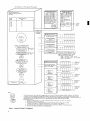
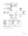
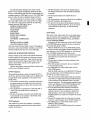
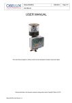
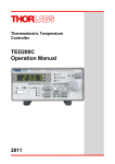
Major components comprising a System/360 Model 65
consist of an IBM 2065 Processing Unit, IBM 2365
Processor Storage, IBM 2361 Core Storage, IBM 2860
Selector Channels and IBM 2870 Multiplexer Channel.
Input/output (I/O) devices are attached to the channels
through control units (Figure 1).
There are five models of the Model 65: G65, H65, 165,
IH65, and J65. These models differ only in the amount of
2365 Processor Storage required with a 2065 Processing
Unit. The significant differences are:
IBM
System/360
Model
Processing
Unit
Model
G65
2065G
H65
2065H
165
20651
IH65
2065IH
J65
2065J
Description
Requires one 2365 Processor Storage Modell
(131, 072 bytes of storage)
Requires one 2365 Processor Storage Model 2
(262, 244 bytes of storage)
Requires two 2365 Processor Storage Model 2
(524, 288 bytes of storage)
Requires three 2365 Processor Storage Model 2
(786,432 bytes of storage)
Requires four 2365 Processor Storage Model 2
(1,048,576 bytes of
storage)
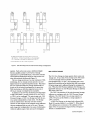
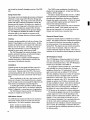
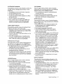
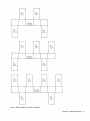
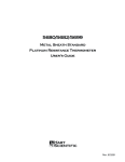
Outline configurations of the Model 65's, produced by
the various combinations of a 2365 Processor Storage and
a 2065 Processing Unit are shown in Figure 2.
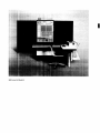
The system control panel is located at one end of the
2065 Processing Unit. One or two optional IBM 1052
Printer-Keyboards may be placed adjacent to the 2065
Processing Unit reading board, to serve as an operator's
console.
The standard features for an System/360 Model 65
include:
Universal Instruction Set
Interval Timer
Storage Protection (both fetch and store)
Optional features for any System/360 Model 65
include:
2361 Core Storage (Modell and 2)
1052 Printer-Keyboard Model 7 Attachment (max of 2)
Channel-to-Channel Feature
Direct Control Feature
2870 Multiplexer Channel
7070/7074 Compatibility Feature (Models H65, 165, IH65,
and J 65 only)
Emergency Power-Off Control (for interconnected units)
7080 Compatibility Feature (Models H65, 165, IH65, and
J65 only)
7090/7040/7044/7090/709411 Compatibility Feature (Models
165, IH65, and J65 only)
Multiprocessing System (two 2065 Model I's, IH's, or J's, each
with Multisystem and Direct Control features, and from two to
four 2365 Processor Storage Model 13's)
The multiprocessing features provide a means of interconnecting two Model 65 systems so that the main storage
of each processing unit is accessible to the other. The 2365
Processor Storage Model 13's are used in multiprocessing
systems only; they are basically the same as 2365 Model
2's except that they have a double BCU/storage interface
which enables the storage to be shared by both processing
units in the system. (2365-2's can be connected to 236513's at the customer's location.) All main storage of both
systems is shared and is considered as a single unit when
the systems are operating as a single system in a shared storage environment. All I/O units may be attached to either
or both processing units. The multiprocessing features are
noted in Figure 1 and are described in Appendix A.
A variety of control units and input/output devices are
available for use with the Model 65. Descriptions of
specific input/output devices appear in separate publications. Configurations for the I/O devices and systems
components are also available. See IBM System/360
Bibliography, Form A22-6822.
2365 PROCESSOR STORAGE MODELS 1 AND 2
The 2365 Processor Storage Models 1 and 2, is the main
storage for the Model 65. Model 1 has a storage capacity of
262,144 bytes.
Each 2365 Processor Storage has a basic 750 ns storage
cycle, with access to eight bytes (doubleword) in parallel.
A store function is possible on a byte basis and any number
or combinations up to eight contiguous bytes can be
stored in one storage cycle. Byte locations are consecutively
numbered starting with zero. An addressing exception is
recognized when any part of an operand is located beyond
the maximum available main storage capacity.
Each 2365 Model 2 contains two independent storage
sections, each with its own address and storage buffer
System Description
5
Main Storage Cycle: 0.75 microseconds, 750 nanoseconds
IBM 2365 Processor torage
(0.75 microsecond)
Modell: 131,072 Bytes
Model 2: 262,144 Bytes
Model 13: 262,244 Bytes
One Modell used with G65
One Model 2 used with H65
Two Model2'sused with 165
Three Model 2's used with IH65
Four Model2'sused with J65
Two to four Model 13's used in
multiprocessing system.
IBM 2065 Processing Unit.
Storage bytes obtained per access:
Eight Bytes
System
Model
2065 Processing Unit
Model
G65
H65
165
IH65
J65
G
H
I
IH
*
IBM 2361 Core Storage
(8 microseconds)
Modell: 1,048, 576 bytes
w.odel 2: 2, (1f7 , 152 bytes
(Without interleaving; one
Model 1 or one to four
Model2's)
(With interleaving; two
Model l's or two or four
Model2's)
To Model
50,65,
ar 75
J
IBM 2860 Selector Channel
First Sel ector Channel
Channel-to-Channel
Adapter t
Maximum - one compatibility feature
(
7070;7074 Compatibility ) }
(
7080 Compatibil ity
Models H,I,IH,J
Only
)
709 /7040/7044/7090/7094/
7094" Compatibility
Models I,IH;J
Only
}
Channel-to-Channel
Adapter t
Third Selector Channel
Channel-to-Channel
Adapter t
M
Attachment
'-./
BM 1052 Adapter (Requires control unit position
on channel). Max of 2.
~
Each selector channel addresses up to 256 I/O
devices, one at a time. Operation is in burst
mode with overlapped processing. The IBM
2860 Selector Channel has three models:
Model 1 - one channel } Max _ two units
Model 2 - two channels
Min _ one unit or 2870
Model 3 - three channels
IBM 2870 Multiplexer Channel
_ _~_-I For concurrent operation of
Addresses up
to 192 I/O
Devices
2870 and 2860, the 2870 has
-----.----/ priority over the 2860.
Attachment
'--./
Addresses up
to 161/0
Devices
Addresses up
to 161/0
Devices
(
Multisystem
*
)
8
} Models I, IH, J
Only
Addresses up
to 16 i/o
Devices
Addresses up
to 161/0
Devices
NOTES:
* The Universal Instruction Set includes the two storage protection instructions, plus the following subsets: Standard, Commercial, and Scientific.
A Channel-to-Chonnel Adapter option (one per 2860 chan) permits interconnection of two channels. One channel position can connect to one
channel position on any other IBM System/360 channel. Only one Channel-to-Channel Adapter needed per connection; it counts as one control unit.
Input/Output Control Units and devices are shown on the IBM System/360 Input/Output Configurator, Form A22-6823.
Multiprocessing System:
1. Consists of two 2065's Model I, IH, or J with multisystem and direct control features, and of two to four 2365-13's.
2. 2365-13 used in multiprocessing systems only.
3. The Model of 2065's used in a multiprocessing system is determined by the number of storage units in the system:
two 20651's if two 2365-13'5, two 20651H's if three 2365-13's, and two 2065-J's if four 2365-13's.
4. One multisystem feature and one direct control feature required on each of the two 2065's in a multiprocessing system.
5. 2361 cannot be install ed with 2065 that has multisystem feature.
Figure 1. System/360 Model 65 Configurator
6
I
H65
-2365
G65
2365
Mod
1
165
Mod
2365
Mod
2
2
2365
Mod
2
2065
Mod
H
2065
Mod
G
2065
Mod
I
I
L
';-_l
I
___ ,
L
.--2365
Mod
2
r---
J65
r---
2365
Mod
2
2365
Mod
2
.---2365
Mod
2
I H65
ms
T365
Mod
2
**
Mod
2
2065
Mod
L-- __
.----2365
Mod
2
..---2365
Mod
2
**
2065
Mod
IH
J
- -
J
rI -*
I
r-----l
L--
L.J
*L-shaped console table may bend to either the left or the
right (option). U-shaped console table, as shown for Model
J65, is provided on any model that attaches two 1052-7's.
**Third 2365 Mod 2 can be in either end position.
Figure 2. 2065 Processing Unit and 2365 Processor Storage Configurations
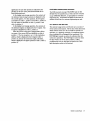
registers. Each section can access a doubleword (eight
bytes) in parallel and has 131 ,072 bytes of storage
organized into 16,384 doublewords. One section contains
even-numbered doublewords while the other section contains odd-numbered double words (Figure 3).
The two storage sections are two-way interleaved. With
interleaving, the two storage sections operate in an overlapped manner for improved sequential access. This means
that two sequential (odd-even) storage doublewords (16
bytes) can be referenced (overlapped) at the same time.
With interleaving, an effective sequential access rate of
400 ns per storage word (eight bytes) is possible.
In addition to the two-way interleaving (overlap) within
a single 2365 Model 2, storage accesses to any two 2365's
or 2361's can be overlapped. The main storage unit, 2365
Processor Storage, or 2361 Core Storage used with the system, operate independently of each other. The Storage
units are related only in that they serve the common
function of main storage and are assigned storage addresses
that are contiguous from one unit to the next. Because
each storage unit is independent, the access of information
within the address range of each unit can be overlapped.
2361 CORE STORAGE
The 2361 Core Storage is a large capacity direct access core
storage unit. It has a basic 8-usec storage cycle, with access
to two words (eight bytes) in~para1lel. The data access
time (double word) is 3.6 usec. The remaining time is overlapped with execution and no further delay will occur unless
the same storage unit is addressed during the remaining 4.4
usec. When the 2065 Processor addresses 2361 Storage, overlapped I/O references to 2365 Processor Storage are allowed.
The reverse is also true.
The 2361 is an extension of the main (processor) storage;
addresses are contiguous with the 2365 Processor Storage
addresses. The 2361 Modell has a storage capacity of
1,048, 576 bytes and the Model 2 a storage capacity of
2,097, 152 bytes.
A 2361 Core Storage can be shared with a System/360
Model 50, another Model 65, or a Model 75. When shared,
2361 addresses are an extension of the addresses of the
larger of the two processor storages involved. Storage protection is a standard feature.
System Description
7
131,072 Bytes
16,384 Double
Words
131,072 Bytes
16,384 Double
Words
Double Word 4
Double Word 2
Double Word 0
Double Word 5
Double Word 3
Double Word 1
tttttttt
tttttttt
2 Words -- 8 Bytes
2 Words -- 8 Bytes
All instruction descriptions appear in IBM System/360
Principles of Operation. Timing information for each of the
instructions is found in the instruction timing section of
this manual.
The 2065 Processing Unit contains the following major
logical parts:
Arithmetic-logic units
Local store
General registers
Floating-point registers
Read-only storage
Storage control unit
Arithmetic-Logic Unit
Figure 3. 2365 Processor Storage Model 2 Two-way Interleaving
The 2361's can be specified for two-way interleaving.
Interleaving provides an addressing scheme between two
2361's that permits the overlapping of read/write storage
cycles in sequential operations. A sequential access rate
of 4 usec per doubleword is possible and sequential access
speeds of 2 megabytes (two million bytes) per second are
possible.
One 2361 Modell or four 2361 Model 2's, without
interleaving, can be used with Model 65. Two 2361
Modell's or two or four 2361 ModeI2's, with interleaving,
can be used with Model 65. 2361's not equipped for twoway interleaving cannot be intermixed with 2361's
equipped for interleaving.
During the time a channel is transferring data at high
speed to or from a 2361, the CPU may not be able to
access that 2361 or any other attached 2361 if two-way
interleaving is not used.
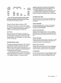
2065 PROCESSING UNIT
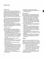
The 2065 Processing Unit is the central processing unit
(CPU) for all Model 65's. The 2065 Processing Unit consists of data registers, interconnecting data paths and
sequence controls. These facilities provide for addressing
main storage (2365 ,Processor Storage), for fetching instructions in the desired order, and for initiating the communications between main storage and external devices
(Figure 4).
The basic data path, with two arithmetic registers,
allows for high speed and simplified implementation of
the System/360 instruction set. In addition, an instruction buffer permits high-speed instruction preparation and
overlap of most instruction fetch time.
The Model 65 is provided with the universal instruction
set. The universal instruction set includes the standard
instruction set, plus the instruction of the decimal feature,
the floating-point feature, and the storage protect feature.
8
Two working arithmetic registers allow for high speed and
simplified implementation of the arithmetic and logic
operations. A parallel adder is a 60-bit wide binary adder
used to facilitate handling of the long floating-point
operations. The serial adder is an eight-bit decimal adder,
also used as a binary adder. In addition, the logical
functions OR, AND, and Exclusive OR can be effected.
Local Store
Local store is a small high-speed storage unit providing
registers for general machine working storage plus the
general and floating-point registers. Only the general and
floating-point registers are addressable by the main program.
General Registers
The general registers are used in address arithmetic and
indexing, and as accumulators in fixed-point arithmetic
and logical operations. The general-purpose registers have
a capacity of one word (32 bits plus four parity bits). For
some operations two adjacent registers can be coupled
together providing a doubleword capacity. The general
registers are implemented in local store and have a cycle
time of 0.2 usec per four bytes.
Floating-Point Registers
Four floating-point registers are available for floating-point
operations. These registers are two words (eight bytes)
in length and can contain either a short (one-word) or a
long (two-word) precision floating-point operand. The
floating-point registers are implemented in local store
and have a cycle time of 0.2 usec per four bytes.
Read Only Storage
The control function of the Model 65 is achieved by the
use of a read only storage (ROS). The ROS is self-addressable, and contains predetermined information of a nondestructive nature used to control the functions of data
flow and instruction execution. ROS is not directly
addressable by the main program. Modification of the
I
One Byte
Selector
Channel
2365 Processor Storage
(Main Storage)
te
Selector
Channel
8 Bytes
8 Bytes
H' ,Hj l'
One
2361 Core Storage
I:::
t~
:=:
~
A,a.&,a
<I,j
_I
loco I Storage
16 General Reg
4 Floating Point
Re~ isters
Storage
Control
Unit
,
I:n
"--v--J
J
y
8 Bytes
One
One
te
te
o-O-ne-~By-t-e--;
One
Read
Only
Storage
4 Bytes
Multiplexer
Channel
~
Working Registers and Switching
Circuitry of CPU
te
60 Bits
60 Bits
,
,U
I
~
60 Bits
,..
\
,111 J
'"
Parallel
A:lder
I
~
,j
/
One
Byte
One
Byte
M
One
Byte
ROS
Control
,
1
I
Data Width
2365 Processor storage
2361 Core Storage
General registers
Floating-point registers
Parallel adder
Serial adder
Basic machine cycle
2860 selector channel
2870 Multiplexer channel
Burst mode
Multiplexer mode
Selector subchannel
8 bytes
8 bytes
1 word
2 words
60 bits
1 byte
1 byte
1 byte
1 byte
1 byte
1 byte
Access/Speed/Rate
0.75 microsecond storage cycle
8 microsecond storage cycle
200 nanoseconds
200 nanoseconds/word
200 nanoseconds
200 nanoseconds
200 nanoseconds
1.3 million bytes/sec
110 kb to 670 kb
110 kb*
110 kb*
180 kb, each (reduced to 100 kb
on 4th subchannel)
Comment
All models
All models
16 General registers
4 Floating-point registers
8 bytes to storage
8 bytes to storage
*Reduced by activity on selector subchannels
Figure 4. Model 65 Data Flow Diagram and System Statistics.
System Description 9
unit is made by physically changing a portion of the ROS
unit.
Storage Control Unit
The storage control unit handles all processor and channel
references to main storage (2365 Processor Storage and
2361 Core Storage). The storage control unit operates in
parallel with and is effectively independent of both the
processor and all channels. Its function is to handle all
requests for use of storage and to determine action to be
taken in case of simultaneous requests either between
channels or between channels and the processor (Figure
4). It is designed to minimize the number of storage
references made by the channels or processor and to
permit overlap of storage.references, whenever possible.
Checking
Extensive checking capability is built into all units of the
Model 65 based largely on a byte parity check. All data
transfers are checked for correct parity both within and
between units of the system. All storage references in
either the 2365 Processor or 2361 Core Storage are
checked for proper parity within the unit itself.
The 2065 Processing Unit includes checking of data
transfers, arithmetic functions, as well as performing a
parity check of the ROS control words.
The 2860 Selector Channel and 2870 Multiplexer
Channel check parity of data transfers, and check the
correctness of its arithmetic function.
CHANNELS
Channels provide the data paths and direct control for
I/O control units and the I/O devices attached to the
control units. Channels relieve the CPU of the task of
communicating directly with the I/O devices and permit
data processing to proceed concurrently with I/O operations.
Data is transferred one byte at a time between an I/O
device and a channel. Data transfers between a channel
and the storage control unit are parallel by eight bytes for
both selector and multiplexer channels (Figure 4).
A standard I/O interface provides a uniform method
of attaching I/O control units to all channels, making the
Model 65 adaptable to a broad spectrum of applications.
The 2860 Selector Channel and the 2870 Multiplexer
Channel are available for the Model 65.
2860 Selector Channel
The 2860 Selector Channel provides for the attachment
and control of burst mode I/O control units and associated devices. The 2860 is available in three models:
Modell-provides one selector channel
Model 2-provides two selector channels
Model 3-provides tluee selector channels
10
Two 2860's in any combination of models can be
attached to the processing unit. At least one 2860 (any
model) or 2870 is required.
The selector channel permits data rates of 1.3 million
bytes per second. I/O operations are overlapped with
processing and depending on the data rate, all selector
channels can operate concurrently. A full set of channel
control and buffer registers permits each channel to
operate with minimal interference.
A maximum of eight control units can be attached to
each selector channel. Each channel may have more
than one unit connected to it, but only one device per
channel may transfer data at any given time.
Channel-to-Channel Feature
A channel-to-channel adapter is available as an optional
feature. The adapter permits the communication between
two System/360 channels, thus providing the capability
for interconnection of two processing units within the
System/360. The adapter uses one control unit position
on each of the two channels. Only one of the two
connected channels requires the feature. There can be a
maximum of one channel-to-channel adapter per channel.
2870 Multiplexer Channel
The 2870 Multiplexer Channel provides for the attachment of a wide range of low to medium speed I/O control units and associated devices. One 2870 Multiplexer
Channel can be attached to the Model 65.
The multiplexer channel provides up to 196 sub channels, including four selector subchannels. The basic
multiplexer channel has 192 subchannels; it can attach
eight control units and can address 192 I/O devices.
The basic multiplexer channel can overlap the operation
of several I/O devices in multiplex mode or operate a
single device in burst mode. One to four selector subchannels are optional with a 2870. Each selector subchannel can operate one I/O device concurrently with
the basic multiplexer channel. Each selector subchannel
permits attachment of eight control units for devices
having a data rate not exceeding 180 kb. Regardless of
the number of control units attached, a maximum of
16 I/O devices can be attached to a selector subchannel.
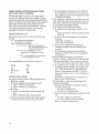
The maximum aggregate data rate for the multiplexer
channel ranges from 110 to 670 kb depending on the
number of selector subchannels installed. Selector subchannels 1-3 may each operate concurrently at up to
180 kb; selector sub channel 4 has a maximum data-rate
of 100 kb. Each selector subchannel in operation
diminishes the basic multiplexer channel's maximum datarate of 110 kb; the relationship to maximum data-rates
for concurrent selector subchannel operations is shown in
the following table:
I
Basic
Multiplexer
Channel
1l0kb
88kb
66kb
44kb
30kb
Selector Sub channels
1st
180kb
180kb
180kb
180kb
2nd
180kb
180kb
180kb
3rd
180kb
180kb
4th
100kb
Aggregate
Data Rate
1l0kb
268kb
426kb
584kb
670kb
Note: The 180 kb maximum data-rate for selector subchannels pertains to attachment of magnetic tape devices; timing
factors other than data-rates may preclude attachment of direct
access storage devices having lesser data-rates.
Channel-to-Channel Adapter Connection to 2870
The 2870 may be connected to another system channel
for channel-to-channel interconnection of two System/360
channels. The channel-to-channel adapter however, is
installed on the other channel, not on the 2870.
2870 Priority
When both 2860 and 2870 channels are installed, the
2870 is connected to the end of the channel cable. When
the 2870 operates concurrently with one or more 2860
channels, however, the 2860 channels 1 and 2 have priority
over the 2870 channels.
SYSTEM CONTROL PANEL
The system control panel, located at one end of the 2065
Processing Unit, provides the switches, the keys and the
lights necessary to operate, monitor and control the
Model 65. The need for operator manipulation of manual
controls is held to a minimum by the system design and
the governing supervisory program.
The operator control section of the system control
panel can be duplicated once to provide a remote operator
control panel that may be mounted on a 2150 Console or
a 2250 Display Unit Modell. An optional console
typewriter input/output function can be provided by a
1052 Printer-Keyboard mounted either adjacent to the
console table reading board or on a 2150 Console .
. A detailed description of operator functions provided
by the switches, keys and lights of the control panel is
located in the system control panel section of this manual.
INTERHUPTION TIMES
Interruption times vary for the class of interruption and
the type of instruction being executed at the time of the
interruption.
External Interruption
External interruption time is 3.15 usec; it extends from
the time the external interruption is discovered and
honored to the next instruction.
Supervisor Call Interruption
Supervisor Call Interruption time is 3.95 usec, including
instruction time; it extends from the time Supervisor Call
interruption is discovered and honored to the next instruction.
Program Interruption
Program interruption time is equal to or less than 3.15 usec;
it extends from the time the program interruption is discovered and honored to the next instruction.
Machine Check Interruption
Machine check interruption time is 50 usec, including scan
out and reset time; it extends from the time the machine
check interruption is discovered to the next instruction.
I/O Interruption
The I/O interruption time is 4.65 usec (average); it extends
from the time the CPU takes a pending interruption from
the channel to the storing of the old PSW and the CSW.
System Description
11
Relationship of Model 65 to Other Models of IBM System/360
MODEL-DEPENDENT FUNCTIONS
The compatibility rule of System/360 does not apply to a
number of detail functions for which neither the frequency
of occUrrence nor usefulness of results warrants identical
action on all models. These functions are concerned with
the handling of invalid programs and machine malfunctions,
and are explicitly identified in System/360 Principles of
Operation, Form A22-6821, in the section "Functions
that May Differ Among Models." Whenever model
dependency exists, the definition of System/360 allows
choice in implementation or specifies that the operation is
unpredictable. The intent is that the user should ignore
results that are defined as unpredictable and should not
base his program on any function where choice in implementation is permitted.
Considering any particular installation and operation,
the operation normally is not truly unpredictable; the
action may depend on the particular system components
or on the input data. The purpose of this section is to
describe how some of the model-dependent functions are
performed on the Model 65.
It should be noted, however, that writing a program on
the basis of information contained in this section is in
violation of the rules of compatibility of System/360. If
a program relies on a function that is model dependent, it
may not run on another model of System/360. Even if the
program takes into account the model-dependent operation
of all other models of System/360, difficulties may be
encountered if and when new models of System/360 are
introduced. Furthermore, a mandatory engineering change
may in some instances require a change in the execution
of a model-dependent function in a machine installed in a
customer's office, and hence may require changes in a program making use of such model-dependent information.
INSTRUCTION EXECUTION
The Diagnose instruction is used for compatibility feature
operation and for maintenance purposes. When the Model
12
65 is equipped with a compatibility feature, the 12 field of
the Diagnose instruction can be coded to allow entry into
Emulator mode. When 12 =02, the Diagnose instruction
becomes an Enter Emulator Mode instruction. Further
information on use of the Diagnose instruction with the
compatibility feature is described in the following publications: IBM System/360 Special Feature Description,
709/7040/7044/7090/7094// Compatibility Feature for
System/360Models 65 and 67, Form A27-2715;IBM
System/360 Special Feature Description, 7074 Compatibility Feature for System/360 Models 50 and 65, Form
A27-2717; and IBM System/360 Special Feature
Description, 7080 Compatibility Feature for System/360
Model 65, Form A27-2716.
MACHINE-CHECK INTERRUPTION
For a machine-check interruption, the old PSW is stored
at location 48 with a zero interruption code. The state of
the CPU is scanned out into the CPU diagnostic scan-out
area, which is 22 double words (176 bytes) in size and
starts at location 128; the channel scan-out area is three
doublewords in size, starting at location 304.
INSTRUCTION-LENGTH CODE
When the instruction-length code in the program old PSW
is zero, the exception was not necessarily caused by the
last instruction executed. Interruptions that cause a zero
instruction-length code to be set in the program old PSW
are referred to as imprecise program interruptions, and
the exceptions causing such interrupts are referred to as
imprecise exceptions. By contrast, a program interruption
associated with a non-zero instruction-length code, and
the corresponding exception, are referred to as precise.
In the Model 65, an imprecise program exception can occur
only when a protection check (store only) is encountered.
I
System Control Panel
Operational control of IBM System/360 Model 65 is
centralized in the system control panel on the 2065
Processing Unit (frontispiece). The control panel contains
indicators, switches, keys, and register displays for the
operator's use. The operator control section of the system
control panel can be duplicated once to provide a remote
operator control panel that may be mounted on a 2150
Console or a 2250 Display Unit Modell. An optional
console typewriter I/O function can be provided by an
additional 1052 Printer-Keyboard.
The control panel is used to:
1.
2.
3.
4.
Turn system control on and off.
Reset the system.
Initial Program load information (IPL).
Store, display, and alter information in storage,
registers, and program status word (PSW).
5. Provide operator-to-machine communication (in
conjunction with the 1052).
6. Permit operator intervention.
7. Perform customer engineering (CE) maintenance.
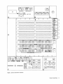
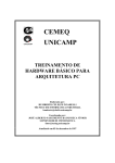
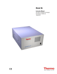
The system control panel (Figure 5) contains the
switches and indicators necessary to operate and control
the system. Switches and indicators are also provided
for operator intervention and for customer engineering
operations.
The operator control sections (sections G and C) are
located in the lower- and upper-right portions of the
system control panel. For monitor control operations,
an identical control section can be provided on an IBM
2150 Operator's Console. Operator control sections are
the same throughout the System/360 line, providing
operations with compatibility between machines. These
sections are described both in this section and in the IBM
System/360 Principles of Operation manual.
Operator intervention controls and indicators are
located in sections E and F of the system control panel.
These are also described both in this section and in the IBM
System/360 Principles of Operation manual. Appendix B
summarizes all system control panel controls and indicators.
The customer engineer uses all controls and indicators;
however, many of the controls and indicators located in
sections A, B, E, and F are intended primarily for customer
engineering use and are not functionally described in this
publication.
Through use of the control panel, the operator can
perform the following important system functions:
1. Reset the system.
2. Store and display information in storage, in registers,
and in the PSW.
3. Load initial program information.
These functions are described in the IBM System/360
Principles of Operation manual.
OPERATOR CONTROLS
The main functions provided by the operator controls are
the control and indication of power, initial program loading,
operator-to-machine communication (by external interruption), and indication of system status.
Operator controls and indicators are as follows:
Name
EMERGENCY PULL
POWER ON
POWER OFF
LOAD UNIT
LOAD
INTERRUPT
SYSTEM
MANUAL
WAIT
TEST
LOAD
Panel
C
G
G
G
G
G
G
G
G
G
G
Type
Pull switch
Pushbutton, backlighted
Pushbutton
Rotary switches (3)
Pushbutton
Pushbutton
Light
Light
Light
Light
Light
Notes:
1. Operator intervention controls are described later in
this section.
2. All pushbuttons have momentary action.
EMERGENCY PULL Switch
Pulling this switch turns off all power beyond the powerentry terminal on every unit that is part of the system or
that can be switched onto the system; therefore, the switch
controls the system proper and all off-line and shared
control units and 110 devices.
The switch latches in the out position and can be restored to its normal position by maintenance personnel
only.
When the EMERGENCY PULL switch is in the out position, the POWER ON pushbutton is ineffective.
POWE R ON Pushbutton
Pressing this pushbutton initiates the power-on sequence of
the system.
System Control Panel 13
As part of the power-on sequence, a system reset is performed in such a manner that the system performs no instructions or I/O operations until explicitly directed. The
contents of main storage are preserved.
The POWER ON pushbutton is backlighted (white light)
to indicate when the power-on sequence is completed.
Any abnormal power condition causes the light to change
from white to red. The pushbutton is effective only when
the EMERGENCY PULL switch is in the normal (in)
position.
SYSTEM Light
This light is on when the CPU cluster meter or customer
engineering meter is running.
MANUAL Light
This light is on while the CPU is in the stopped state.
Several manual controls are effective only while the CPU is
stopped (the MANUAL light is on). Press START to exit
from this state (to resume processing).
POWER OFF Pushbutton
WAIT Light
Pressing this pushbutton initiates the power-off sequence
of the system.
The contents of main storage (but not the controls in
storage associated with the protection feature) are preserved, provided the CPU is in the stopped state. The
pushbutton is effective while power is on the system.
There is a 5-second delay between depression of the button
and the removal of power.
This light is on while the CPU is in the wait state; in this
state, bit 14 of the current PSW is a 1 (see Appendix B for
PSW format). To exit from wait state (to resume instruction processing), an interruption (normally external or I/O
or an IPL must be provided.
INTERRUPT Pushbutton
Pressing this pushbutton requests an external interruption.
The interruption is taken when not masked off and when
the CPU is not stopped. Otherwise, the interruption
request remains pending. Bit 2S in the interruption-code
portion of the current PSW is made 1 to indicate that the
INTERRUPT pushbutton is the source of the external
interruption. (See Appendix B for the PSW format.) The
pushbutton is effective while power is on the system.
LOAD UNIT Switches
Three rotary switches provide the 11 rightmost I/O address
bits used for initial program loading. The leftmost rotary
switch has eight positions, labeled 0-7. These positions
are used for the channel address. The middle (l6-position)
rotary switch, labeled O-F hexadecimal, is for the control
unit address. The rightmost (I6-position) rotary switch is
for the device address. These switches may be set without
disturbing CPU operations. The actual IPL does not start
until the LOAD pushbutton is pressed.
LOAD Pushbutton
Pressing this pushbutton starts initial program load. The
control is effective while power is on in the system. Loading
is from the I/O unit specified in the three LOAD UNIT
switches. Pressing the LOAD pushbutton first causes a
system reset and then loads the fust 24 bytes of information from the load unit into the first 24 bytes of main
storage. Note that the LOAD pushbutton is normally
used when the CPU is in the stopped state.
14
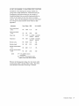
Note: The states indicated by the WAIT and MANUAL
lights are mutually independent. The wait state is programinitiated and is terminated by an IPL or an interruption,
whereas, the manual state is initiated and terminated by the
operator. The status of the SYSTEM light is a function of
the running condition of the cluster meter; the SYSTEM
light is on while the cluster meter is running. The following
table shows the possible configurations of the three lights
while power is on:
SYSTEM
Light
MANUAL
Light
WAIT
Light
Off
Off
Off
Off
Off
Off
On
On
Off
On
Off
On
On
On
On
On
Off
Off
On
On
Off
On
Off
On
* Abnormal
CPU
State
I/O
State
Wait
Stopped
Stopped,
Wait
Running
Wait
Stopped
Stopped,
Wait
Not working
Not working
Not working
*
Undetermined
Working
Working
Working
condition
LOAD Light
This light is on during initial program loading; it is turned
on when the LOAD pushbutton is pressed and is turned
off after loading of the new PSW is completed successfully.
TEST Light
This light is on when a manual control is not in its normal
position or when a maintenance function is being performed
for CPU, channels, or storage.
I
POWt:II CHECK
MAIIIIII
~Cr
STOll FIIAME
I
Z S 4
0
Loon/
M,...8111/METEII ilL
~
CHAII FIIAME
I 2 3
0000
000
M,...8111 CHAIIIIELIITOil
METEII
I
I
STOllE
FIlAME
[ I
=:::\ ;;::::.
I ]CHAII
:....-:::::: ~ FIIAME
~~
-g0:"--
4
[:
LOWEll
~ lIoa LOCATE
0
i~O~ii~5-ii'{)'il.:o~1
lIAISE
~J
CPU
A
10
§
~l
C
B
20
15
30
25
45
40
35
50
E
II
I
I
r
I
000000000000000000 000000000000000000
0
I
I
II
I
'.'II-U
.... 11-11
".,
LWTfIT
I,. 1ft,'" , HY CT."
.... ..
I
'18 '-'1
''''-11-
II
l.IIPm.
~
".
,._11-11
000000000000000000 000000000000000000
F
0
.. , 0
Sfll .... t
lMlf'Tnt
~1"1111
000000000000000000 000000000000000000
E
o:':tIC.CltS
IIR,I.C
'."-1""AI.
......
0
..•.. •.
I
0
11_11-"
I
000000000000000000 000000000000000000
G
I
0
I
I I
I lUll
I
(
, unCUL"
lIT. . . . . ,
I LIIf Jill
.......,-11
II
I
ISTM . . . ,
I
9
10
BYTE I
II 12
14
I ~~~ ~~ ~~ ~I
15
~ ~~~ ~~ ~~I ~~~~~~~~
K
DATA
V
.v rl::
BYTE 2
15
Y
4
~~~~~~~~
&
~rl::
ADOIIESS
~~I~~~~~~ ~~~~I~~~~
M
MAIN STOR ADORESS COMPARE
10
MH:AT
~~
.:l':'~
~'":'r ~
STORAGE
NOleATE
i!..~~::
20
15
STOIA;[
c:~~
SElECT
f. ~
WD~
~ ~: ~
=!:!I .~=L
D..UU
f
=:tl" *~
"Oroooo
I
0001
I4 g8:9
0 100
1010151417141
@
1010101513121
15
I
.,
0101
0 I I 0
0 I I I
f+m
18"
~
~
!: Yb
cf.....!...!....!..
F
121 &4 H
11024512251
1000111::'1 COMPAIIE
1°1234567
~
[j
31
so
&1
az n
I
4
~ ~~~ ~~~~I ~~~?~~~~ I HHUHI ~ ~ ~ ~ ~ ~ ~ ~I
L
.-,
:so
H-IS
51 57 58 5.
TEST MODE
~
24 25 21 27 21 29
~
Il.fUT
-31
BYTE
t ..... Ut •• HI,"".
..... ITt
JIC,I'Ni
' UOirllI'
000000000000000000 000000000000000000
J
1-)1
flC'I'll_TIIl
II
000000000000000000 000000000000000000
H
' _a-M,nn
.lm••• ,nCl,1IPT
IllIPTlSf
HHMH
30
25
lOCAL
2
I 1
[j
III~
•
0-11
ST~IE
F'
10
I I
11-21
45
40
35
Ie
50
!£rUT
IISI
*~
~ ~
I:D\i~I:~
RATE
1.5.
PROCESS
~mE
STEP-aCYClE
...--~mE
CYClE
STOI"E
IIIMlIIT
D
D
GJ EJ I
SYSTEM
RElET
I
CHECk
RESET
PI.
001
ftlUTAIitT
TRANSFER
OISPLAY
Ie
B- G
.ElTA.T
nT II
I
~
OUT
I
PONER
ON
I
I
PONER
OfF
I
I
LOAD UNIT
®
\
0 "
...'"
'"P:.::
",'"
n
8 b
\
"'~
0
n
...
'"p .:
...
8 b ..
0 0000
I Er"-··m'-Ell
ITEllIII'
LOAD
G
Figure 5. System Control Panel- Model 65.
System Control Panel
15
Any abnormal switch setting on the system control
panel or on any separate maintenance panel for the CPU,
storage, or channels that can affect the normal operation of
a program causes the TEST light to be on. (The TEST light
does not reflect the state of marginal voltage controls.)
The normal position for all rotary switches is straight
up; for all toggle switches, the normal position is straight
out. When not in their normal positions, the following
switches cause the TEST light to be on:
ADDRESS COMPARE STOP
DEFEAT INTERLEAVING
PULSE MODE
CPU CHECK
REPEATINSN
REPEAT ROS ADDRESS
CEMode Key
TEST MODE: ROS/PROC/FLT
RATE
DISABLE INTERVAL TIMER
STOP ON STORAGE CHECK
Note that certain functions under control of the Diagnose
instruction, certain circuit breaker conditions, and certain
thermal conditions may also turn on the TEST light.
OPERATOR INTERVENTION CONTROLS
Sections F and E of the system control panel contain the
controls required for the operator to intervene in normal
programmed system operations. These controls are intermixed with the customer engineering controls. Only the
operator intervention controls on these panels are described in this section.
Operator intervention controls provide the system reset
and the store and display functions.
START Pushbutton
This pushbutton provides a means of starting the CPU in
the Process, Instruction Step, Single Cycle, or Single Cycle
Storage Inhibit mode, depending on the position of the
RATE switch.
1. If this switch is pressed after a normal halt, instruction
processing continues as though no halt had occurred.
Pending interruptions are taken after execution of the
nrst instruction.
2. If the pushbutton is pressed after an abnormal halt or
system reset, the results will not necessarily be
predictable.
3. The type of operation executed by the START pushbutton depends on the position of the RATE switch
(described later in this section).
STOP Pushbutton
This pushbutton provides the capability of completely
terminating machine operations without destroying the
machine environment.
16
1. The CPU proceeds to the end of the machine instruction being executed at the time the STOP command is
recognized.
2. All waiting interruptions not masked off are executed.
3. All I/O operations in process are allowd to be completed.
4. The CPU is placed in the stopped state.
S. The operator can continue normal program operation
by pressing the START pushbutton, or he can execute
certain manual operations (e.g., an instruction-step
operation).
RATE Switch
This rotary switch, which selects the rate at which instructions are executed, has four positions: PROCESS,INSN
STEP (instruction step), SINGLE CYCLE, and SINGLE
CYCLE STORAGE INHIBIT.
Pressing the START pushbutton with the RATE switch
in the PROCESS position causes the system to operate at
the normal clock speed of 200ns.
With the RATE switch set to the INSN STEP position,
the system executes one complete machine instruction for
each depression of the START pushbutton. (The interval
timer is disabled during Instruction Step mode.)
1. Any machine instruction can be executed in this mode.
Interruptions are executed after the instruction is
completed.
2. The stop point is identical with that achieved by the
STOP pushbutton.
3. When I/O operations are started, they are completed
to the interruption point.
4. The TEST light is on when RATE switch is in the
INSN STEP position.
With the RATE switch set to the SINGLE CYCLE position, each depression of the START pushbutton advances
the CPU by one 200ns machine cycle.
1. When the instruction being single-cycled uses asynchronous devices, it single-cycles through all CPU functions
of the instruction to the initiation point of the asynchronous operation. The asynchronous operation starts
on the next depression of the START pushbutton and
runs to the completion point in a normal manner.
2. If the asynchronous device initiates an interruption
request during a single-cycle operation it is not automatically executed. The interruption is divided into
single operations. More than one depression of the
START pushbutton is required to complete the transfer
ofPSW's.
3. During CPU storage cycles, more than one clock pulse
is taken for each depression of the START pushbutton.
4. The TEST light is on when RATE switch is in the
SINGLE CYCLE position.
The SINGLE CYCLE INHIBIT position is for customer
engineering functions.
I
SYSTEM RESET Pushbutton
TIlls pushbutton resets the on-line channels, control units,
and CPU controls, including machine checks, to their
initial state.
1. The pushbutton is active in all modes of operation.
2. All check indicators are reset.
3. The data flow registers are not reset.
4. A system reset does not affect equipment in off-line
channel operations.
S. The CPU is placed in the stopped state.
6. Since a system reset can occur in the middle of an
operation, the contents of the PSW and of result
registers and storage locations are unpredictable.
CHECK RESET Pushbutton
This pushbutton provides a means of resetting all check
indIcators in the CPU to the non error state.
1. Pressing the pushbutton resets all CPU check triggers
and latches to the no-check state (it is a subset of the
SYSTEM RESET pushbutton).
2. TIlls reset clears all CPU logic check indicators on the
system control panel.
3. If the CPU is stopped because of a machine check,
processing continues when the check indicators are
reset. In this case, results are not predictable.
STORAGE SELECT Switch
TIlls toggle switch provides a means of selecting the storage unit that is to be addressed by the ADDRESS keys
when used with the DISPLAY or the STORE pushbutton.
1. The MAIN position selects the main storage for
addressing when storing or displaying.
2. The LOCAL position selects the local store for addressing when storing or displaying.
3. The MAIN BYTE position selects the main storage for
addressing when storing or displaying but causes only
the byte addressed by the three low-order ADDRESS
keys to be stored.
DATA Switches
These 64 toggle switches provide a means of manually
data into the location selected by the STORAGE
SELECT switch and the ADDRESS switches.
1. The 64 switches are arranged in hexadecimal groups
to permit data entry.
2. Correct parity is generated automatically.
3. Switches S3 through 63 are used as a count when the
pulse mode count function is being performed.
ent~ring
STOR E Pushbutton
This pushbutton provides a means of storing information
into any address in the storage specified by the STORAGE
SELECT toggle switch.
1. The contents of the DATA switches are placed in the
location specified by the ADDRESS switches and
the STORAGE SELECT switch.
2. Correct parity is generated automatically.
3. If the STORAGE SELECT switch is in the MAIN
position, the entire contents of the DATA keys are
stored in the main storage.
4. If the STORAGE SELECT switch is in the LOCAL position, the five low-order ADDRESS switches specify the
local store location in which the contents of the right
half of the configuration in the DATA switches will be
stored. ADDRESS switch 19, when in the 0 position,
permits storing in the general-purpose registers; when
in the I position, switch 19 permits storing into the
floating-point registers. The specific address is determined by the five low-order ADDRESS switches.
ADDRESS switches 19 and 20, when set to 1's, address
the working register (a local storage register not accessible under program control).
S. If the STORAGE SELECT switch is in the MAIN BYTE
position, the byte of data in the DATA switches
specified by the three low-order bits of the ADDRESS
switches is stored in main storage at the address specified
by the ADDRESS keys.
6. The machine must be in a stopped state for this pushbutton to function.
DISPLAY Pushbutton
ADDRESS Switches
These 24 toggle switches provide a means of manually
selecting an addressable location in storage.
1. The 24 switches are arranged in hexadecimal groups
to permit storage addressing.
2. Correct parity is generated automatically.
3. Switches 2 through 20 are used with the ADDRESS
COMPARE switch to select an address for an address
compare stop or an address compare sync.
4. Switches 0 through 11 are used for selection of ROS
address and for a ROS compare sync. The sync pulse is
provided whenever the ROS address compares successfully with the configuration placed in these switches.
This pushbutton is pressed to display information in the
location specified by the STORAGE SELECT switch and
the ADDRESS switches.
1. If the STORAGE SELECT switch is in the MAIN BYTE
or MAIN position, the information in main storage at
the address specified by the ADDRESS switches is
displayed in the ST and AB registers. (See "Roller
Indicators.")
2. If the STORAGE SELECT switch is in the LOCAL position, the information in the local store is displayed in
the T-register. (See "Roller Indicators.") The machine
must be in a stopped state for this pushbutton to
function.
System Control Panel
17
ADDRESS COMPARE STOP Switch
This toggle switch provides a machine stop on a CPU storage compare.
1. In the center (normal) position, a synchronizing pulse
(for CE use) is provided whenever the storage address
bus compares successfully with bits 2 through 20 of the
ADDRESS keys.
2. In the down (stop) position, the machine stops at the
end of the instruction in progress whenever the storage
address bus compares successfully with bits 2 through
20 of the ADDRESS keys.
3. The TEST light is on whenever this switch is in the
down position.
PSW REST ART Pushbutton
This pushbutton switch provides a method to restart programs by loading a new PSW from the contents of storage
locations 0-7.
1. With the machine in the stopped or reset state, pressing
this pushbutton causes a new PSW to be fetched from
storage locations 0-7.
2. The CPU continues processing after the new PSW is
fetched if the RATE switch is in the PROCESS position.
SET IC Pushbutton (Instruction Counter)
This pushbutton is pressed to enter an address into the
instruction address of the current PSW.
1. This pushbutton sets bits 40-63 of the current PSW
to the value specified in the ADDRESS switches.
The CPU is reset to the start of an I-fetch at that address.
The instruction at the specified location is then fetched
and loaded into the instruction buffer, and the instruction counter is updated. The machine then returns to
the stopped state.
2. The machine must be in the stopped state for this
pushbutton to function.
Note: The instruction address is displayed in the D-register when the CPU is in the stopped state. (See "Roller
Indicators".) The new address contained in the mstruction
counter is one or two doublewords more than the instruction address contained in the address switches.
2. With this switch in the STOP position, the check
triggers are set when a machine check is detected. The
CPU stops and no logout occurs. If the CHECK
RESET pushbutton is pressed, the operation is resumed,
but the results are not predictable.
3. With this switch in the DSAB position, the check triggers are set when a machine check is detected. Logout,
interruption, and termination do not occur. The
check triggers can be reset by pressing the CHECK
RESET pushbutton or by a system reset.
4. The TEST light is on whenever this switch is in the
STOP or the DSAB position.
LOG OUT Pushbutton
This pushbutton provides a means of logging the machine
status into storage.
1. Pressing this pushbutton causes the machine status
to be stored in fixed locations in main storage.
2. This pushbutton is inactive under a normal processing
condition. Logout is the process of storing the status
of most of the CPU indicators and registers in main
storage. The logout area occupies 44 words or 176
bytes of main storage, starting at byte 128.
STOP ON STORAGE CHECK Switch
This switch provides a means of inhibiting storage accesses
when a storage check occurs so that the indicators will not
be changed. Storage checks resulting from accesses by
channels and other processors also cause a stop. The
switchable indicators (rollers) are checked to determine the
error and the address of the failing main storage word.
This switch should be operated with the CPU CHECK
switch in the STOP position. The storage-stop state caused
by a storage check is different from the stopped state.
The TEST light is on whenever this switch is in the down
position.
STORAGE INDICATE Switch
Information from a maximum of eight storage arrays
(Model J 65; two 128K byte storage arrays per 2365) can
be displayed by the roller indicators. Depending on the
setting of this switch, information from storage arrays 1
through 4 or from storage arrays 5 through 8 is displayed.
CPU CHECK Switch
This toggle switch provides a means of controlling the
system when a machine check is encountered.
1. With this switch in the PROC position, the CPU stops
when a machine check is detected. Also, the machine
status is logged to storage and an interrupt trap is
initiated if the machine check mask in the PSW is a 1.
If the machine check mask in the PSW is a 0, the check
is ignored except that the check triggers are turned on.
18
ROLLER INDICATORS
Section E contains six rows of 36 indicator lights. Above
each row of lights is an opening, and behind each opening
is a roller that can be positioned to indicate the significance
of the related indicator lights for various operations. Each
roller is manually placed in one of six positions by a positioning knob at the right side of panel E (Figure 1). The
I
significance of each roller position is indicated by the
printing on the face of the panel located beside the related positioning knob.
In the display main storage operation, the contents of
the addressed main storage locations are displayed in the
ST and AB registers. For this operation, the ST register
is identified on roller 1, position 3 and roller 2, position 3.
The AB register is identified on roller 3, position 3 and
roller 4, position 3.
In the display local storage operation, the contents of
the addressed register are displayed in the T-register. The
T-register is identified on roller 2, position 3.
When the CPU is in the wait or stopped state, all but
two parts of the current PSW are identified on roller 4,
position 1. The two exception are: (1) the instruction
address, which is displayed in the D-register (roller 1,
position 2), and (2) the instruction length code (ILC),
which is displayed in E-register positions 0 and 1 (roller 5,
position 3).
CUSTOMER ENGINEERING CONTROL
The ROS (read-only storage) TRANSFER and the RESTART FLT I/O pushbuttons, as well as all lever switches
except STORAGE SELECT, are principally for custom~r
engineering use. All switches and lights and the meter m
sections A and B are for customer engineering use only.
KEY SWITCH AND METERS
The customer usage meter and CE meter are on section F
of the system control panel. The CE key switch determines
which of these meters is to be run while the system is in
operation, i.e., initiating, executing, or completing instructions, including I/O and assignable unit operations. The
SYSTEM light, located on section G, indicates when the
system is in operation. The TEST light is turned on when
the key switch is in the CE meter position. (Other
conditions that turn on this light are listed in the TEST
light description earlier in this section.)
System Control Panel
19
Instruction Times
INTRODUCTION
Two types of instruction times are listed in this section:
the average times for all instructions executed by the
Model 65, and the detailed times for all variable field length
(VFL) instructions executed by the Model 65. All
symbols used in these lists are defmed in the Legends
description, which precedes the lists. Standard IBM
System/360 instruction timing formula legends have been
used.
The times within each listing are provided for instruction execution when instructions and data are located in
IBM 2365 Processor Storage. Additional time must be
added if the instructions and data are located in IBM 2361
large capacity storage (LCS); the additional times are
given in the last part of this section.
Unless otherwise noted, all times in this section are in
microseconds. Complete information on each instruction
is presented in the publication IBM Syst~m/360 Principles
of Operation, Form A22-6821.
Timing Considerations
Unless otherwise noted, the following conditions were
used in the development of the instruction-time listings:
1. The time required for indexing by a base register is
included in the times given. For those instructions that
can be double.indexed (indicated by one or two
asterisks in the Instruction column on the list of average
instruction times, an additional 0.2 usec (two asterisks),
0.10 usec (Model G-one asterisk) or 0.15 usec (Models
II, I, J - one asterisk) must be added to the times given
in the table.
2. In all arithmetic operations, positive and negative
operands are equally probable.
3. Each bit location has equal probability of containing bit
values 0 or 1, and each bit location is independent of
other bit locations.
4. Addresses for unsuccessful branches are valid unprotected storage locations.
S. Decimal data may contain digit values 0-9 in each digit
position with equal probability. When either the multiplier of a Multiply Decimal instruction or the divisor of
a Divide Decimal instruction contains the digits 5 or 6
in each position, the resulting instruction time will be
slower than average (worst case). An incremental
decrease in instruction time is realized as the digits
descend from 5 to 0 or ascend from 6 to 9.
6. Instructions may start on even or odd halfwords with
equal probability.
20
7. Interruptions are not reflected in these timings.
8. All timings provided include both decoding and execution times for instructions.
Timing Assumptions
Unless otherwise noted, the following assumptions were
used in the development of the instruction-time listings:
1. For the Add Decimal (AP) and Subtract Decimal (SP)
instructions, the first operand (i.e., the destination
field) is assumed to be equal to or greater than the
length of the second operand (i.e., the source field).
2. In the Edit and Mark (EDMK) instruction, an address
is stored once; i.e., this instruction is used with a single
field, or a line with only one numeric field is employed
rather than a complete print line.
3. For a multiprocessing system, refer to the "Instruction
Timing" portion of Appendix A for additional timing
considera tions.
4. The instruction times for floating-point instructions
depend on both the number of hexadecimal digits that
are preshifted and post-shifted, and on the number of
times the result is recomplcmented. The floating-point
instruction times given in this section are a weighted
average of these variables.
5. For the Pack (PACK), Unpack (UNPK) and Move with
Offset (MVO) instructions, it is assumed that no overflow
field occurs.
6. In Models IH65 and J65, add 50 ns to instruction times
(RX, RS, SI, and SS formats) given for each reference
to third and fourth storage elements for cable delay
(see Figure 2).
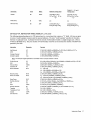
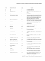
LEGENDS
Legends for Instructions with Multiple Timing Formulas
Legends Al to A4 are timing formulas for the Store Multiple
or Load Multiple instruction, depending upon quantity of
general registers and the position of doubleword boundaries:
AI: Use if the number of registers is 2, and if the
operand lies on doubleword boundaries.
A2: Use if the number of registers is> 2 and even,
and if the operand lies on doubleword boundaries.
A3: Use if the number of registers is even, and if the
operand does not lie on doubleword boundaries.
A4: Use if the number of registers is odd.
Legends E5 and E6 are timing formulas to use for the
Execute instruction, depending upon instruction length
code and varying conditions:
I
E5: Use if subject instruction is a successful branch.
E6: Use if subject instruction is not a successful branch.
Legends Vito V6 are timing formulas to use for the
Move instruction, depending upon the location of operand
fields:
VI: Use if first and second operand fields start and
end on doubleword boundaries.
V2: Use if first and second operand fields start at
corresponding byte addresses within doublewords,
but do not lie on double word boundaries.
V3: Use if frrst and second operand fields do not start
at corresponding byte addresses within doublewords or if N < 8.
V5: Use if Nl ~ 'N2
V6: Use if Nl > N2
Note: A byte address of a double word can have the value
0,1,2,3,4,5,6, or 7. A doubleword (8 bytes) must have
an address that is a multiple of the number 8, but the four
low-order bits of the binary address of a byte within a
doubleword can have any value 0 to 7.
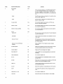
Legends for Instructions with Single Timing Formulas
B
E
ED
Fl
Gl
G3
GR
M
MK
N
N1
N2
N3
N6
Total number of bytes of the frrst operand
which are processed. Applies to instructions
with a single length field.
Time for the subject instruction which is
executed by the Execute instruction.
External Delay.
1 if the branch operation is successful.
o otherwise.
1 if an overflow interruption occurs (PSW
bit 36=1) or fixed point divide interruption
occurs.
o otherwise.
0 if operand to be converted is positive.
1 otherwise.
Number of general registers loaded or stored.
Greater of N 1 or N2.
Number of times the mark address is stored in
the Edit and Mark instruction.
Total number of bytes in the frrst operand for
those instruction with a single length field.
Total number of bytes in the frrst operand
( destination).
Total number of bytes in the second operand
(source).
Total number of bytes which overlap between
the first and second operands. N3 = 0 for
nonoverlapping fields, or for overlapping fields
where the address of the second operand is
greater than or equal to the first operand
address.
Number of bytes of the field which lie outside
of that part of the field bounded by doublewords.
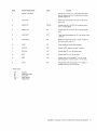
NWBBI = Number of word boundary crossovers for that
part of the first operand processed.
NWBB2 = Number of word boundary crossovers for that
part of the second operand processed.
NWBL 1 = Number of word boundary crossovers for the
frrst operand.
NWBL2 = Number of word boundary crossovers for the
second operand.
NWBLIL2 = Number of word boundary crossovers for
that part of the first operand which consists
of N2 bytes of high-order zeros.
~
Quotient found by dividing by 4 the number
of positions to be shifted.
QS
Smaller of Nl - 8 or Nl - N2.
r4
Remainder after dividing by 4 the number of
positions to be shifted.
S1
1 if r4 = 3, or if ~ = 0
2 if r4 = 3, and ~ = 0
o otherwise.
S2
-1 ifr4 = 0
1 ifr4 = 1, and ~ = 0
o otherwise.
S3
0 if r4 = 0, and ~ f 0
= 1 if r4 = 0, and ~ = 0
3 if r4 = 1
= 5 if r4 = 2 or 3
S4
0 ifr4 = 0
4 if ~ = 0 and r4 = 1, or if ~ f 0 and f4 = 2
3 if ~ = 0 and r4 = 2, or if ~ f 0 and r4 = 3
2 if ~ = 0 and r4 = 3
5 if ~ f 0 and r4 = 1
TI
1 if the result field is recomplemented (Le.,
changes sign).
o otherwise
T2
1 if the result field is zero.
o otherwise.
T3
1 ifN2 < 1/2 (NI + 1)
o otherwise.
T6
OifN2 ~ 4
1 otherwise
T7
OifNI ~ 8
1 otherwise.
0 if fields do not overlap.
T8
1 otherwise.
0 if any non-zero function byte is found.
T9
1 otherwise.
T 12
1 if R 1 field of the Execute instruction is not
zero.
o otherwise.
U1
Select out delay plus device delay.
U2
Device delay for HALT I/O sequence.
W
Total number of doublewords in the first
operand for those instructions with a single
length field.
Instruction Times
21
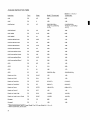
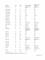
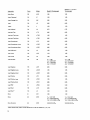
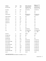
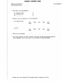
AVERAGE INSTRUCTION TIMES
Instruction
Form
Mnem
Model G Timing (usec)
Models H, I, IH, and J
Timing (usec)
Add
RR
AR
0.65
0.65
Add*
RX
A
1.50
1.40
Add Decimal
SS
AP
3.6+0.2M+0.2N 1+
0.1N2+T1 (2.0+0.4N1)
+1. 2T 2
3.4+0.2M+0.2N 1
+0.1N2+T1 (2.0+0.4N1)
+1. 2T 2
Add Halfword*
RX
AH
1.90
1.80
Add Logical
RR
ALR
0.65
0.65
Add Logical*
RX
AL
1.50
1.40
Add Normalized Long
RR
ADR
1.72
1.72
Add Normalized Long*
RX
AD
2.55
2.45
Add Normalized Short
RR
AER
1.68
1.68
Add Normalized Short·
RX
AE
2.53
2.43
Add Unnormalized Long
RR
AWR
1.65
1.65
Add Unnormalized Long*
RX
AW
2.50
2.40
Add Unnormalized Short
RR
AUR
1.64
1.64
Add Unnormalized Short*
RX
AU
2.48
2.38
AND
RR
NR
1.25
1.25
AND*
RX
N
2.10
2.00
AND
SI
NI
1.96
1.73
AND
SS
NC
3.0+0.5N+. 2N 3
2.8+0.5N+0. 2N 3
Branch and Link
RR
BALR
1.25
1.20
Branch and Link*
RX
BAL
1.25
1.20
Branch on Condition
RR
BCR
0.7+0.5F 1
0.7+0.4F1
Branch on Condition*
RX
BC
0.8+0.4F 1
0.8+0. 3F 1
Branch on Count
RR
BCTR
1.08+0.17F 1
0.98+0.17F 1
Branch on Count**
RX
BCT
1.25
1.15
Branch on Index High
RS
BXH
1.6-0.2F 1
1.6-0.2F 1
Branch on I ndex Low or Equal
RS
BXLE
1.6-0.2F 1
1.6-0.2F 1
Compare
RR
CR
0.65
0.65
Compare*
RX
C
1.50
1.40
*When double-indexed, add 0.10 usec (Model G) or 0.15 usec (Model H, I, IH, or J).
**When double-index, add 0.2 usec.
22
I
Instruction
Form
Mnem
Model G Timing (usec)
Models H, I, IH, and J
Timing (usec)
Compare Decimal
SS
CP
3.67+0.2M+0. 13N 1
+0. 1N 2
3.47+0.2M+0.13N 1
+0.1 N2
Compare Halfword*
RX
CH
1.90
1.80
Compare Logical
RR
CLR
0.65
0.65
Compare Logical*
RX
CL
1.50
1.40
Compare Logical
SI
CLI
1.50
1.40
Compare Logical
SS
CLC
3.1+0.4B
2.9+0.4B
Compare Long
RR
CDR
1.26
1.26
Compare Long*
RX
CD
2.10
2.00
Compare Short
RR
CER
1.24
1.24
Compare Short*
RX
CE
2.08
1.98
Convert to Binary*
RX
CVB
7.7+0. 2G3+0.2G 1
7.6+0.2G3+0.2G1
Convert to Decimal*
RX
CVD
8.98+0.4G3
8.65+0.4G3
Divide
RR
DR
8.45+0. 15G 1
8.45+0. 15G 1
Divide*
RX
D
8.80+0. 15G 1
8.70+0. 15G 1
Divide Decimal
SS
DP
6.15+4.6N 1-4. 7N 2
+2. 2N 2 (N1- N 2)+
0.6T6+1.2T7OS
5.95+4.5N 1-4.7N 2
+2.2N 2 (N1- N 2)+
0.6T 6+ 1. 2T 7 0S
Divide Long
RR
DDR
13.35
13.35
Divide Long*
RX
DD
14.20
14.10
Divide Short
RR
DER
6.55
6.55
Divide Short*
RX
DE
7.40
7.30
Edit
SS
ED
3.40+0. 7N+0.1 N2
3.20+0.63N+0.1 N2
Edit and Mark
SS
EDMK
3.40+0.63N+0.1 N2
+1.2MK
3.20+0.63N+0.1 N2
+1.2MK
Exclusive OR
RR
XR
1.25
1.25
Exclusive OR*
RX
X
2.10
2.00
Exclusive OR
SI
XI
1.96
1.73
Exclusive OR
SS
XC
3.0+0.5N+0. 2N 3
2.8+0.5N+0.2N 3
Execute*
RX
EX
E5 = 1.55+E
E6 = 2.8+E+0.4T 12
E5 = 1.45+E
E6 = 2.6+E+0.4T 12
Halt I/O
SI
HIO
1.5+U1+ U 2
1.4+U1+ U 2
Halve Long
RR
HDR
1.25
1.25
*When double-index, add 0.10 usec (Model G) or 0.15 usec (Model H, I, IH, or J)
Instruction Times
23
I nstruetion
Form
Mnem
Model G Timing (usee)
Models H, I, IH, and J
Timing (usee)
Halve Short
RR
HER
1.05
1.05
Insert Character*
RX
IC
1.50
1.40
I nsert Storage Key
RR
ISK
2.85
2.85
Load
RR
LR
0.65
0.65
Load*
RX
L
1.30
1.20
Load Address*
RX
LA
0.75
0.75
Load and Test
RR
LTR
0.65
0.65
Load and Test Long
RR
LTDR
1.05
1.05
Load and Test Short
RR
LTER
0.85
0.85
Load Complement
RR
LCR
0.65
0.65
Load Complement Long
RR
LCDR
1.05
1.05
Load Complement Short
RR
LCER
0.85
0.85
Load Halfword*
RX
LH
1.50
1.40
Load Long
RR
LDR
1.23
1.05
Load Long*
RX
LD
1.50
. 1.40
Load Multiple
RS
LM
A1=1.50
A2 = 0.9+0.4G R
A3 = 1.3+0.4G R
A4 = 1.1+0.4GR
A1 = 1.40
A2 = 0.8+0.3GR
A3 = 1.2+0.3GR
A4 = 1.0+0.3G R
Load Negative
RR
LNR
0.95
0.95
Load Negative Long
RR
LNDR
1.05
1.05
Load Negative Short
RR
LNER
0.85
0.85
Load Positive
RR
LPR
0.95
0.95
Load Positive Long
RR
LPDR
1.05
1.05
Load Positive Short
RR
LPER
0.85
0.85
Load PSW
SI
LPSW
2.40
2.20
Load Short
RR
LER
0.65
0.65
Load Short*
RX
LE
1.30
1.20
Move
SI
MVI
1.56
1.33
Move
SS
MVO
V1 = 2.2+1.6W
V2 = 3.3+0.2N+0.2N 6
V3 = 3.13+0.38N+0.2N 3
V 1 = 2.0+1.4W
V2 = 3.1+0.2N+0.2N 6
V3 = 2.93+0.38N+0.2N 3
Move Numerics
SS
MVN
3.0+0.5N+0. 2N 3
2.8+0.5N+0. 2N 3
*When double-index, add 0.10 usec (Model G) or 0.15 usec (Model H, I, IH, or J).
24
Instruction
Form
Mnem
Model G Timing (usec)
Models H, I, IH and J
Timing (usec)
Move with Offset
SS
MVO
3.13+0.27Nl+0.3N2
+0.4N3, If Nl ~ N2
2.93+0.27N 1+0.3N2
+0.4N3, If Nl ~ N2
Move Zones
SS
MVZ
Multiply
RR
MR
4.45
4.45
Multiply*
RX
M
4.90
4.80
Multiply Decimal
SS
MP
3.97+3.5N 1-2.9N2
+1.0N2(Nl-N 2)
3. 77+3.4N 1-2.9N2
+1.0N2(Nl- N 2)
Multiply Halfword*
RX
MH
5.10
5.00
Multiply Long
RR
MDR
7.25
7.25
Multiply Long*
RX
MD
7.70
7.60
Multiply Short
RR
MER
4.05
4.05
Multiply Short*
RX
ME
4.50
4.40
OR
RR
OR
1.25
1.25
OR*
RX
0
2.10
2.00
OR
SI
01
1.96
1.73
OR
SS
OC
3.0+0.5N+0.2N 3
2.8+0.5N+0.2N 3
Pack
SS
PACK
3.07+0.27N 1+0.2N 2,
N2+ 1
IfNl>-2-
2.87+0.27N 1+0.2N 2,
N2+ 1
IfNl > - 2 -
Read Direct
SI
ROD
2.80+ED
2.70+ED
Set Program Mask
RR
SPM
0.85
0.85
Set Storage Key
RR
SSK
1.8
1.8
Set System Mask
SI
SSM
1.90
1.80
Shift Left Double
RS
SLDA
0.9+0·4q4+ 0 . 25 3
0.9+0.4q4+ 0 . 25 3
Shift Left Double Logical
RS
SLDL
0.9+0.4q4+ 0 . 2S 3
0.9+0.4q4+ 0 .2S 3
Shift Left Single
RS
SLA
0.7+0.2Q4+0.2S1
0.7+0.2Q4+0.2S1
Shift Left Single Logical
RS
SLL
0.7+0. 2Q4+0. 2S 1
0.7+0.2Q4+0.2S1
Shift Right Double
RS
SRDA
0.9+0.4Q4+0.2S 4
0.9+0.4Q4+ 0 . 2S 4
Shift Right Double Logical
RS
SRDL
0.9+0.4Q4+0.2S4
0.9+0.4Q4+0.2S 4
Shift Right Single
RS
SRA
0.9+0.2Q4+0.2S2
0.9+0.2Q4+0.2S2
Shift Right Single Logical
RS
SRL
0.9+0.2Q4+0.2S2
0.9+0.2Q4+0.2S2
Start I/O
SI
SIO
1.50+Ul
l.4O+Ul
.3.0+0.5N+0.2N 3
2.8+0.5N+0. 2N 3
*When double-indexed, add 0.10 usec (Model G) or 0.15 (Model H, I, IH, or J)
Instruction Times
25
Instruction
Form
Mnem
Model G Timing (usee)
Models H, I, IH, and J
Timing (usee)
Store*
RX
ST
1.16
0.93
Store Character*
RX
STC
1.56
1.33
Store Halfword*
RX
STH
1.96
1.73
Store Long*
RX
STD
1.16
0.93
Store Multiple
RS
STM
A1
A2
A3
A4
A1
A2
A3
A4
Store Short*
RX
STE
1.16
0.93
Subtract
RR
SR
0.65
0.65
Subtract*
RX
S
1.50
1.40
Subtract Decimal
SS
SP
3.6+0.2M+0.2N 1+
0.1 N2+T 1 (2.0+0.4N1)
+1. 2T 2
3.4+0.2M+0. 2N 1+
0.1 N2+T 1(2.0+0.4N1)
+1. 2T 2
Subtract Halfword*
RX
SH
1.90
1.80
Subtract Logical
RR
SLR
0.65
0.65
Subtract Logical*
RX
SL
1.50
1.40
Subtract Normalized Long
RR
SDR
1.72
1.72
Subtract Normalized Long*
RX
SO
2.55
2.45
Subtract Normalized Short
RR
SER
1.68
1.68
Subtract Normalized Short*
RX
SE
2.53
2.43 .
Subtract Unnormalized Long
RR
SWR
1.65
1.65
Subtract Unnormalized Long*
RX
SW
2.50
2.40
Subtract Unnormalized Short
RR
SUR
1.64
1.64
Subtract Unnormalized Short*
RX
SU
2.48
2.38
Supervisor Call
RR
SVC
4.15
3.75
Test and Set
SI
TS
1.90
1.80
Test Channel
SI
TCH
1.50+U1
1.4O+U1
Test I/O
SI
TID
1.50+U1
1.4O+U1
Test Under Mask
SI
TM
1.70
1.60
Translate
SS
TR
2.14+1.88N
1.94+1.78N
Translate and Test
SS
TRT
4.3+1.3B-1.0T9
4.1+1.2B-1.0T 9
=1.56
=0.76+0.4GR
=1.56+0.4GR
=1.16+0.4GR
*When double-indexed, add 0.10 usee (Model G) or 0.15 usee (Model H, I, IH, or J)
26
=1.33
=0.53+0.2GR
=1.33+0.2GR
=0.93+0.2G R
Instruction
Form
Mnem
Model G Timing (usec)
Models H, I I H, and J
Timing (usec)
Unpack
SS
UNPK
3.OtO.4N1+0.1N2+
0.2T3,if N1+1 ~ N2
2.8+0.4N 1+0.1 N 2+
0. 2T 3,if N1+1 ~ N2
I
2
2
Write Direct
SI
WRD
2.3
2.2
Zero and Add
SS
ZAP
3.7OtO.2M+0. 1N 1+
0.1 N2+0.72T8+1.2T2
3.SOtO.2M+0. 1N 1+
0.1N2+0.72T8+1.2T2
DETAILED VFL INSTRUCTION TIMES, (MODELS H, I, IH, and J)
The following timing formulas are for VFL instructions (i.e., instructions that contain an "L" field). All times are given
in terms of word boundary crossovers and the operand addresses. The term "word boundary" specifies the boundary
between two physical words. A physical word is the amount of information fetched in a single storage cycle. (This is
64 bits for all Model 65's.) Thus, the number of word boundary crossovers is one less than the number of doublewords
spanned by the field.
Instruction
Mnemonic
Formula
Add Decimal
AP
3.7S+0.2M+1.6NWBL1+0.8NWBL2+T 1(2.2+2N 1+1.6NWBL1 )+1.2T2
AND
NC
3.16+0.2N+1.6NWBL1+0.8NWBL2+0.2N3
Compare Decimal
CP
3.7S+0.2M+1.00NWBL1+0.8NWBL2
Compare Logical
CLC
3.16+0.2B+0.8NWBB1+0.8NWBB2
Note: The Compare Logical operation is terminated when an unequal condition is found.
Divide Decimal
DP
6.2+4.4N1-4.8N2+2.20N2(N1 -N2)+0.8NWBL1+0.8NWBL2+0.6T6+1.2T7OS
Edit
ED
3.S7+0.43N+1.6NWBL1+0.8NWBL2
Edit and Mark
EDMK
3.S6+0.43N+1.6NWBL1+1.2NWBL2+1.2MK
Exclusive OR
XC
3.16+0.2N+1.6NWBL1+0.8NWBL2+0.2N3
Move Characters
MVC
V1 : 2.Ot1.4W
V2 : 3.36+0.8NWBL1+0.8NWBL2+0.1N
V3 : 3.16+0.6NWBL1+0.8NWBL2+0.2N3+0.2N
Move Numerics
MVN
3.16+0.2N+1.6NWBL1+0.8NWBL2+0.2N3
Move with Offset
MVO
Vs : 3.2+0.4N1+0.6NWBL1+0.8NWBL2+0.4N3
Move Zones
MVZ
3.16+0.2N+1.6NWBL1+0.8NWBL2+0.2N3
Multiply Decimal
MP
4.12+3.4N1 -3.2N2+1.0N2(N1 -N2)+0.8NWBL2+1.6NWBL1 L2
OR
OC
3.16+0.2N+1.6NWBL1+0.8NWBL2+0.2N3
Pack
PACK
3.11+0.2N1+0.1 N2+0.6NWBL1+0.8NWBL2
Subtract Decimal
SP
3.7S+0.2M+1.6NWBL1+0.8NWBL2+T 1(2.2+0.6NWBL1 )+1. 2T2
Translate
TR
2.4+1.6N+1.4NWBL 1
Translate and Test
TRT
3.6+1.0N+1.8NWBB1 -1.0Tg
Unpack
UNPK
3.16+0.2N 1+1.6NWBL1+1.6NWBL2+0.2T3
Zero and Add
ZAP
3.7S+0.2M+0.8NWBL1+0.8NWBL2+·072T3+1.2T2
V6 : 3.2+0.4N2+0.2(N1 -N2)+0.6NWBL1+0.8NWBL2+0.4N3
Instruction Times
27
TIMING ADDENDA FOR OPERATIONS WITH IBM
2361 LARGE CAPACITY STORAGE
Whenever the Model 65 references 2361 large capacity
storage (LCS), additional time must be added to the previously listed instruction times (average and detailed VFL).
Because of overlap and of interleaving where data, addresses,
and location of instructions affect performances, only
approximate (average) times can be described. The times
to be added are calculated as shown in the following
paragraphs; all times are in microseconds.
Instruction Fetch from LCS
When the instruction word is in LCS, add the following
time (B):
B == 2.75+ 1/2(8.00-A)+C if interleaved,
== 2.7 5+8.0(}'A if not interleaved,
where: (1) B must be ~ 2.75 usec.
(2) A ~ 3.5 usec == Difference in time between
two LCS storage references made
within 8 usec of each other.
(3) C == 0.25 usec if the difference in time
between two LCS references is 3.50 usec,
or
C == 0.13 usec if the difference in time between
two LCS references is 3.75 usec
The average added instruction times per format are:
Format
RR
RX, RS, SI
SS
B/4
B/2
3B/4
Operand Fetches and Stores
For operand fetches and stores, add the applicable time:
1. RX Format: Add B
2. RS Format (Multiple Load and Multiple Store):
a. Add B + 3.00 (n-l) if interleaved
b. Add B + 7.00 (n-l) if not interleaved
3. SI Format:
a. Add B (Test Under Mask, Compare Logical, and
Move)
b. Add B + 800 (AND, OR, or Exclusive OR)
4. SS Format (Compare Decimal and Compare Logical):
a. If one 64-bit word is fetched from LCS, add B
28
b. If both operands are fetched from LCS, add 5.00 +
B if interleaved, or add 7.00 + B if not interleaved.
Also, add B for each referenced operand that crosses
a double word boundary.
5. SS Format (Pack, Unpack, Move with Offset, Zero and
Add, Add Decimal, Subtract Decimal, Move Numerics,
Move Zones, AND, OR, and, where both operands are
not on doubleword boundaries, Move):
a. If a source fetch is made to LCS, add B.
b. If a destination fetch (and store) is made to LCS,
add:
(6.00-0.25) (number of bytes processed in 64-bit
word) + B.
c. If both a source and destination fetch are made to
LCS, add:
10.00 + B if interleaved, or
12.00 + B if not interleaved.
d. For the source operand across double word
boundaries, add B for each such additional LCS
reference.
e. For the destination operand across doubleword
boundaries, add 8.00 + B for each such additional
LCS reference.
6. SS Format (Decimal Multiply, Decimal Divide,
Translate, Translate and Test, Edit, and Edit and Mask;
fields of approximately 8 bytes or more are assumed):
a. If only a source fetch is made to LCS, add 2.75 usec.
b. If a destination fetch is made to LCS, add 2.75 usec
for Multiply, Divide, Translate, and Translate and
Test. Also add 10.00 usec for each multiplicand,
divisor, or translated byte, and add 2.75 usec for
each referenced operand that crosses a doubleword
boundary.
c. If both source and destination are located in LCS,
add 2.75 usec to item 3b above.
7. SS Format (Move, with both operands aligned and
doubleword boundaries):
a. If either source reference or destination reference
(not both) is LCS, add:
B + 3.00 (n-I) if interleaved
B + 6.00 (n-l) if non-interleaved
b. If both the source and destination reference are LCS,
add:
B + 6.00 + 10.00 (n-l) if interleaved
B + 7.00 + 14.00 (n-I) if non-interleaved
Where n = number of doublewords.
EFFECT OF CHANGE TO FLOATING-POINT FEATURE
Installation of the floating-point change modifies the
average time of eight instructions. Instruction times for
floating-point instructions depend on the number of
hexadecimal digits that are preshifted and postshifted, as
well as on the number of times the result is recomplemented. Each of the floating-point instruction times listed
is an average of actual execution times which are datadependent.
Form Mnem G65
---
Instruction
H, I, IH, J65
Add Unnormalized
Long
RR
AWR
1.75
1.75
Add Unnormalized
Long*
RX
AW
2.60
2.50
Halve Long
RR
HDR
1.2+0ANC 1.2+0ANC
+0.6 UF
+0.6 UF
Halve Short
RR
HER
1.2+0ANC 1.2+0ANC
+0.6 UF
+0.6 UF
Mu Itiply Long
RR
MDR
7.65
7.65
Mu Itiply Long*
RX
MD
8.10
8.00
Subtract Unnormalized
Long
RR
SWR
1.75
1.75
Subtract Unnormalized
Long*
RX
SW
2.60
2.50
where
UF = 1 if underflow occurs
= 0 otherwise
NC = number of normalization cycles
*Add 0.15 usec when double indexed.
Without the floating-point change, the times given earlier
in this section under "Average Times" apply. The above
times should be used when this change is installed.
Instruction Times
29
Appendix A. Multiprocessing System
INTRODUCTION
The Model 65 mUltiprocessing system comprises two 2065
CPU's and from two to four 2365-13 processor storage units;
this provides a system main storage capacity of 524, 288
(524K), 786,432 (786K), or 1,048,576 (1 ,048K) bytes,
which can be allocated in increments of 262,144 (262K)
bytes. The model of CPU's used in a multiprocessing
system is determined by the number of storage units in the
system, as follows:
CPU Models
Number of
2365-13's
Used
--Two
Two 2065I's
Three
Two 20651H's
Four
Two 2065J's
A multisystem feature and a direct control feature are
required on each CPU. An IBM 2361 Core Storage cannot
be attached in a multiprocessing system.
The multisystem features provide shared-storage,
shared-I/O, and floating-storage addressing capabilities to
the system. One configuration control panel is added to
the system. This panel contains manual controls for
storage and I/O control unit allocation, prefixing, mode
selection, and floating addressing. In addition, the feature
provides CPU mode control (modification of the direct
control features) and modifies the Set System Mask instruction. Each shared storage feature consists primarily of a
double BCU-storage interface. A priority scheme determines which BCU is to have access to the storage unit
and ensures that neither BCU is allowed two successive
references to a particular storage unit if the other BCU is
waiting for access.
In a basic Model 65 system, the CPU and all 2365-2
storage units are attached to a series of frames called a
wall. When processor storage is shared, both CPU's and all
storage units are arranged on a continuous wall (Figure 6).
Note that the configuration control panel is located on the
front of the center frame.
Input/Output
Up to seven channels (one 2870 and six 2860's) can be
attached to each CPU. All I/O units attachable to the
basic Model 65 system are attachable in the mUltiprocessing
system. However, the total number of shared I/O units in
a multiprocessing system cannot exceed the total number
of units attachable in a basic Model 65 system.
TIle two-channel switch feature of the control units
and the channel-to-channel adapter feature of the 2860
selector channels may interconnect the two systems for
30
shared I/O units. A remote switch attachment feature
is required on all I/O units having the two-channel switch
feature. These remote switches comprise the I/O allocation switches on the configuration control panel. To
maximize data throughout, a 2820 Storage Control, if
installed, should attach to the highest-priority channel.
Modes
Three operating modes are selectable at the configuration
control panel: Multisystem, Mod 65, and Partitioned.
TIle basic difference between these modes is in the CPUto-CPU communications.
In Multisystem mode, direct CPU-to-CPU communication is enabled via the multisystem direct control interface.
Also. the Set System Mask instruction causes an interruption in this mode.
Mod 65 mode enables CPU-to-CPU communications via
the basic direct control interface if the DISABLE DIRECT
CONTROL switch is in the center (enable) position. If
this switch is in the down (disable) position, a Read
or Write Direct instruction will cause an operation
exception. The Set System Mask instruction is executed
in this mode as described in IBM System/360 Principles of
Operation. Note that the normal direct control signal and
data lines mayor may not be connected between the two
CPU's in the system; depending on the system configuration,
these lines could be connected for direct control with an
external device.
In Partitioned mode, multisystem direct communications between CPU's is disabled. However, direct control
timing signals 4-7 are enabled (bits 12-15 in the 12 field of
Read and Write Direct are used) if the ENABLE DIRECT
CONTROL switch is in the center position; if the switch is
in the down position, Read and Write Direct are no-op'ed.
Normal Set System Mask operations are enabled in this
mode.
In all three modes, the multisystem feature enables
operation of the I/O and storage allocation switches, the
floating address switches, and the prefix switches.
Compatibility Features
All compatibility features (emulators) available for the
basic Model 65 can be installed. For emulation on a
Model 65 within the multiprocessing system, those
portions of the system required for emulation must be
partitioned out of the system environment; i.e., the 2065
with the compatibility feature, the appropriate amount of
storage, and the required I/O units must be partitioned as
2365
Mod 13
(5Ig-1)
2365
Mod 13
(5Ig-2)
I
Config
ClrI Pnl
I
2065
Mod I
(CPU-2l
2065
Mod I
(CPU-I)
2365
Mod 13
( 51g-1)
2365
Mod 13
(5Ig-2)
I
Config
Ctrl Pnl
2365
Mod 13
(5Ig-3)
I
2065
Mod IH
(CPU-2)
2065
Mod IH
(CPU-I)
2365
Mod 13
(5Ig-4)
2365
Mod 13
(5Ig-2)
2365
Mod 13
(5Ig-3)
2365
Mod 13
( 51g-1)
I
Config
Ctrl Pnl
I
2065
Mod J
(CPU-2)
2065
Mod J
(CPU-I)
Figure 6. Multiprocessing System Outline Configurations
Appendix A. Multiprocessing System
31
a separate system. Access time is minimized by partioning into the emulating system storage units that are
physically closest to the CPU.
Power Control
Additional power control functions are added by the
multisystem feature for safety and for convenience of
the operator. The POWER ON pushbutton on the system
control panel of either CPU turns on power for that CPU
and for all shared and nonshared units controlled by that
CPU. The POWER OFF pushbutton removes power from
that CPU and from all nonshared units controlled by that
CPU; also, power is removed from all shared units if power
has been turned off at the other CPU.
in Multisystem mode to generate direct control signals,
bits 8-11 are ignored.
Bits 12-15 of both direct control instructions are
unchanged and remain under control of the ENABLE
DIRECT CONTROL switch on the 2065 operator's panels.
Program interruptions will not occur on direct control
instructions if the ENABLE DIRECT CONTROL switch
is in the down (disable) position and Multisystem or
Partitioned mode is active.
In addition to the multisystem signals generated by the
Write Direct instruction, one signal (Malfunction Alert) is
machine-generated. All multisystem signals are described
in the following paragraphs.
Malfunction Alert
Metering
The 2365-13 Storage Units have customer usage meters.
The meter records usage when the storage unit is conditioned for operation and is receiving the signal that
either CPU is recording time .. The storage unit is conditioned from each CPU by the Enable position of the
appropriate Storage Allocation switch on the configuration
control panel. Metering in the 2065 is unchanged.
MULTISYSTEM FEATURE
Multisystem Direct Control
The multisystem feature modifies the basic direct control
feature to provide predefmed signals for CPU-to-CPU
communication in Multisystem mode only.
The modification adds one machine- and four programgenerated signals to the basic direct control feature interface.
Direct control signals 0-3 are not used in Multisystem
mode. Instead, bits 8-11 in the 12 field of the Write
Direct instruction are redefined to provide the new multisystem signals as follows:
12 Field
Bit
8,9
External
Interrupt Bit
=00
= 01
= 10
=11
10
11
12-15
=1
27
28-31
Name of Signal
Received*
System Reset
When a SysteIJl Reset signal is received, the storage
selection reference already granted priority by the BCU
of the receiving CPU is allowed to finish. New priority
assignments are blocked for a period of 32 to 48ms,
after which the receiving CPU is reset, as are all storage
units, channels, I/O control units, and devices allocated
to and on-line for that CPU. At the completion of this
reset, the receiving CPU is placed in the stopped state
(MANUAL indicator lit).
----
No signal
System Reset
External Start
Log I/O Interrupts
- -(Reserved)
System Call
Direct Control signals 4-7
*Signals received by other CPU if both CPU's are in Multisystem
mode.
If either CPU in the multiprocessing system is not in
Multisystem mode, bits 8-11 of the Write Direct instruction are effectively ignored.
The Read Direct instruction is not used to generate
multisystem signals; however, if this instruction is used
32
This signal is generated by a CPU when one of the
following conditions occurs:
1. A machine check is detected and the machine check
mask bit is a 1.
2. CPU power is turned off.
3. A system hang-up occurs and the machine check mask
bit is a 1.
The Malfunction Alert can externally interrupt the
receiving CPU, setting bit 26 in the external interruption
old PSW. The receiving CPU is interrupted if its external
interruption mask bit is ai, regardless of the setting of
the Direct Control switch. The failing CPU immediately
stops processing if its machine check mask bit is a 1.
External Start
Either CPU can be started (or restarted) in the same
manner as by the depression ofPSW RESTART by
receiving an External Start signal from the other CPU.
This signal does not reset the receiving CPU. The external
start operation begins immediately if the receiving CPU
is in the Wait or Stopped state; otherwise, the start
operation begins when execution of the current operation
is ended. If an external system reset operation is in progress, the external start is executed when the reset is
finished.
The external start operation initiates retrieval of the
initial-program-Ioading PSW from effective location zero
(the permanent storage area address is determined by the
prefIx and storage allocation switches on the configuration
control panel). Instruction execution starts from the
instruction addressed by the fetched PSW, ending the
external start. No I/O operations are initiated during
external starting, and the old PSW is not stored.
Log I/O Interruptions
If any I/O interruptions are pending in the receiving CPU,
this signal causes a CSW to be stored into location 6410
and causes the channel and I/O device addresses to be
stored into locations 5810 and 5910 in the old PSW.
Normal I/O interruption action and priority are observed.
The> I/O interruption mask bits are ignored.
Since no attempt is made to synchronize the log operation with CPU activity, the receiving CPU should be in the
Wait state with all channel interruptions masked off, or
results may be inconsistent. Any activity except I/O is
overridden. No external interrupts are caused in the
receiving processor. Following a Log I/O Interrupt operation no other signal should be issued between CPU's
except another Log I/O Interrupt or System Reset.
A period of 5usec should be allowed between the
initiation of Log I/O Interrupt and the interrogation of
results in core storage. Another Log I/O Interrupt signal
should not be issued until the previous Log I/O Interrupt
operation has completed logging of the interrupt. A
logout will not occur unless an interruption has occurred
or is pending. The system must be reset before further
action can be initiated.
System Call
This signal causes an external interruption in the receiving
CPU if that CPU is in Multisystem mode and is enabled for
external interruptions with the external interruption mask
bit set to 1. Bit 27 of the external interruption old PSW
is set to 1.
Mod/65 mode becomes effective immediately. Each
switch can select one of three possible modes: Multisystem,
Partitioned, or Mod/65. For a normal multisystem
environment to exist, both Mode switches should be in the
Multisystem position. The setting of these switches does
not affect the function of other switches on the configuration control panel.
Storage Allocation Switches
A Storage Allocation switch for each CPU is associated
with each 2365-13 Storage Unit. The storage unit is
accessible to the CPU to which the switch refers only
when the switch is in the Enable position. If both
switches associated with a particular storage unit are set to
Disable, the storage unit is logically removed from the
entire system, regardless of the setting of either Processor
Mode switch.
Allocation of storage is in increments of 262,144
bytes. At least one storage unit must be allocated to a
CPU for it to operate as an independent system.
Both CPU's can share any or all storage units in any
CPU mode. Active storage can be assigned as a contiguous
block, and any storage unit can be logically removed from
the system.
I/O Control Unit Allocation Switches
Two groups of I/O Control Unit Allocation switches are
provided on the configuration control panel, one group
per CPU. All dual-channel interface I/O control units in
the multiprocessing system will have one allocation switch
per CPU. With these switches, an I/O control unit can be
allocated to either or both CPU's or can be partitioned
out of the system. A change in the status of an allocation
switch becomes effective when that CPU is in the stopped
or wait state.
Configuration Control Panel
Processor mode, prefixing, floating addressing, storage
allocation, and I/O control unit allocation for both CPU's
are all controllable from the configuration control panel.
A Processor Mode switch and a Prefix switch are provided
for each CPU. A Floating Addres$ switch controls the
address range of each storage unit. With each Floating
Address switch are two Storage Allocation switches, one
associated with each CPU.
Processor Mode Switch
The Processor Mode switch for each CPU determines the
mode in which that particular CPU is to operate. Changes
in this switch that involve Multisystem mode are sampled
only when the CPU is stopped. A change in mode involving
Prefix Switches
A Prefix toggle switch for each CPU is located on the
configuration control panel. Each switch has two positions: Enable and Disable. A change in the status of a
Prefix switch becomes effective only when the associated
CPU is restarted (via LOAD pushbutton or External
Start signal). Once prefixing is enabled, all CPU and
channel references to locations within the lowest 4,096
bytes of storage allocated to that CPU are relocated to
corresponding locations within the highest 4,096 bytes.
Also, CPU storage references to the highest 4,096 bytes
are relocated to the lowest 4,096 bytes; this reverse
prefixing is not performed for channel references.
Appendix A. Multiprocessing System
33
Floating Address and Storage Allocation Switches, Valid
Addressing Indicators
One Floating Address switch is provided per 2365-13.
Each switch can assign anyone of the four possible blocks
of addresses to the associated 2365-13:
Switch Label
Address Block
o to 262K
o to 262,143
262K to 524K
524Kto 786K
786K to 1048K
262, 144, to 524, 287
524,288 to 786, 431
786, 432 to 1,048,575
Thus, any 2365-13 in the system can be assigned any block
of these addresses.
Two Storage Allocation switches, one per CPU, are
associated with each Floating Address switch. Each
Storage Allocation switch enables or disables operation
of the associated CPU with one 2365-13. The blocks of
addresses assigned to the 2365-13's allocated to each CPU
should be contiguous; nonprefixed storage references to
units in the power-down or disabled condition will result
in an Invalid Address exception.
Duplicate addressing can exist if two Floating Address
switches are set identically and both associated storage
units are allocated to one or both CPU's. Two Valid
Addressing indicators, one per CPU, are located on the
configuration panel. When an indicator is lit, duplicate
addressing does not exist for the associated CPU. When
an indicator is off, duplicate addressing does exist, and
~ll memory requests from'the associated CPU are blocked
until the situation is resolved. The Floating Address
switches are not interlocked by CPU mode. Varying these
switches for enabled storage units while either CPU is
running may produce unpredictable results or machine
checks.
2365 PROCESSOR STORAGE MODEL 13
Each 2365-13 is basically the same as a 2365-2 except
that it provides a double BCU/storage interface. A priority
scheme determines which CPU will have access to the storage unit and ensures that neither CPU will be allowed two
successive references to a particular storage unit if the
other CPU is waiting for access. Each shared storage unit
has a customer usage meter.
If a CPU "hangs up" in Multisystem mode (Le., fails
to complete any instruction) for a period of 102-1 08ms,
a machine check is forced. The CPU is restrictively reset
to allow a logout to be attempted. The logout contains
a bit indicating that a system hang-up condition has
occurred. A malfunction alert is issued to the other
processor. Excessive duration of the Read Direct instruction may result in a hang-up condition being sensed. To
sense a hang-up condition, the interval timer must be active.
INSTRUCTION TIMING
If prefixing is enabled for a CPU, add 200ns for each
storage reference to a permanent storage area (upper
4,096 bytes and lower 4,096 bytes of storage allocated
to that CPU).
The extra cable length and priority circuits cause a
performance degradation on a shared storage system.
This occurs on every storage reference, regardless of the
CPU mode of operation. The time added to each storage
reference will not exceed the following figures:
Time per Reference (in ns)
Set System Mask Instruction
A Set System Mask instruction decoded in a CPU that is
in Multisystem mode causes a multisystem program
interruption if no other program interruptions are present.
The instruction is suppressed, and an interruption code
of 0012 (hexadecimal) is stored in the program old PSW.
This instruction operates as defined in IBM System/360
Principles of Operation when the CPU is in Partitioned
or Mod/65 mode.
34
CPU1
CPU2
30
65
2
65
30
3
30
100
4
100
30
Placement of the CPU's and storage units is shown in
Figure 6.
Appendix B. Summary of System Control Panel Controls and Indicators
Panel
Switch/l ndicator Name
Type*
A
All
For customer engineer use.
B
All
For customer engineer use.
C
EMERGENCY PULL
PS
Function
When pulled, this switch initiates emergency off in the
system.
For expansion.
D
E
Roller Switches and Indicators
E
DATA 0-31, DATA 32-63
TGL
These 64 switches, in hexadecimal groups, permit manual
entry of data. Correct parity is generated automatically.
E
ADDRESS
TGL
These 24 switches, in hexadecimal groups, select an addressable location in storage. Correct parity is generated automatically.
E
STOR CHK
IND
I ndicates an error in the storage units.
E
PROC CHK
IND
I ndicates an error in the CPU.
F
TEST MODE
REPEAT
TGL
For customer engineer use; should be in center position
for normal CPU operation.
TGL
For customer engineer uses; the PROC position does not
affect CPU operation and is the normal position of this
switch.
ROS/PROC/FL T
There are six 6-position roller switches and 36 indicators
associated with each switch. The roller indicators are
tested between positions of the switch. Position 6 of
roller 6 is used to test the remaining indicators on the
system control panel and on the 2150 console.
F
STORAGE INDICATE
TGL
Selects the storage arrays (1 thorugh 4 or 5 through 8)
that will have information displayed by roller switch
i nd icators.
F
FREQUENCY ALTERATION
TGL
For customer engineer use; effective only when the
CE key switch is in the CE position.
F
DEFEAT INTERLEAVING
TGL
For customer engineer use; PROC is the normal position.
F
STOP ON STORAGE CHECK
TGL
For customer engineer use; should be in center position
for normal operation.
F
DISABLE INTERVAL TIMER
TGL
For customer engineer use; should be in center position
for normal operation.
F
STORAGE SELECT
MAIN
TGL
F
Normal position; selects main storage for storing or
displaying data.
LOCAL
Selects local storage for storing or displaying data.
MAIN BYTE
Same as normal position except that byte selected is
the only byte affected by a manual store operation.
ADDRESS COMPARE STOP
TGL
Stops processing when storage address agrees with bits
2 through 20 of ADDRESS switches. Should be in
center position for normal operation.
Appendix B. Summary of System Control Panel Controls and Indicators
35
Panel
Switch/Indicator Name
Type*
F
CPU CHECK
PROC
TGL
Function
This is the normal position. If the PSW machine mask is
a 1, the CPU stops on detection of a CPU check, and
the status is logged into main storage. If the mask is 0,
the result is the same as if the switch is in the DSAB position.
DSAB
The CPU does not stop on detection of a machine check,
but the check trigger is set.
STOP
The CPU stops on detection of a machine check, but
there is no log-in of data.
F
PULSE MODE
TGL
For customer engineer use; should be in PROC position for normal CPU operation.
F
REPEATINSN
TGL
For customer engineer use; should be in PROC position
for normal CPU operations.
F
REPEAT ROS ADDRESS
TGL
For customer engineer use; should be in center position
for normal operation.
F
RATE
INSN STEP
RTY
CPU executes on machine instruction for each depression
of START pushbutton.
PROCESS
Does not affect CPU operation; CPU operates at normal
clock speed.
SINGLE CYCLE
CPU advances by minimum clock amount for each depression of START pushbutton; all CPU operations are
as in PROC position.
SI NG LE CYCLE STORAGE
INHIBIT
Same as SI NG LE CYCLE position without storage
references.
F
SYSTEM RESET
PB
Resets on-line channels, control units, and CPU controls
(including machine checks) to their initial state.
F
CHECK RESET
PB
Resets all CPU and storage check triggers.
F
PSW RESTART
PB
Loads a PSW from main storage address zero and starts
processing.
F
ROS TRANSFER
PB
For customer engineer use.
F
SETIC
PB
Enters an address from ADDRESS switches into active
(current) PSW.
F
STORE
PB
Enters data into storage location specified by STORAGE
SELECT switch and ADDRESS switches.
F
DISPLAY
PB
Displays data specified by STORAGE SELECT switch
and ADDRESS switches.
F
START
PB
Starts CPU operating in mode selected by RATE switch.
F
STOP
PB
Terminates CPU operation without changing environment.
F
RESTART FLT I/O
PB
For customer engineer use.
F
LOG OUT
PB
Stores CPU status in fixed locations in main storage.
36
Panel
Switch/I ndicator Name
Type*
F
Elapsed Time Meters
Indicate CPU running time. The process meter shows
customer elapsed time; the CE meter shows customer
engineer elapsed time.
F
Key Switch
Determines which elapsed time meter will be used to
record time.
G
POWER ON
PB/IND
I nitiates power on in the CPU and in selected system
units. It is backlighted.
G
POWER OFF
PB
I nitiates power off in the CPU and in selected system
units.
G
LOAD UNIT
RTY
These three switches select the I/O units used by a load
operation.
G
INTERRUPT
PB
Causes an external interruption in system and sets bit
25 of interruption code to a 1.
G
LOAD
PB
G
SYSTEM
IND
Indicates a CPU elapsed time meter is running.
G
MANUAL
IND
Indicates that CPU is in the stopped state.
G
WAIT
IND
Indicates that CPU is in the wait state.
G
TEST
IND
I ndicates that a switch on panel F is not in normal
operating position or that a channel is in test mode.
G
LOAD
IND
I ridicates that a CPU load operation is in progress. A
successful load turns off the indicator.
Function
Resets system and starts a load operation.
* Abbreviations:
IND
PB
PS
RTY
TGL
Indicator
Pushbutton Switch
Pu II Switch
Rotary Switch
Toggle Switch
Appendix B. Summary of System Control Panel Controls and Indicators
37
Index
ADDRESS COMPARE STOP Pushbutton
ADDRESS Switches 17
Arithmetic-Logic Unit, 2065 8
Attachment Capability of Model 65 6
Average Instruction Times 22
18
Channels 10
Channel-to-Channel Adapter 10
CHECK RESET Pushbutton 17
Checking 10
Compatibility Features 5, 6, 12, 30
Configuration Control Panel (Multisystem Feature)
Configurations:
Outline 7, 31
System 6
Configurator 6
Control Panel:
Configuration 33
System 11, 13, 35
Core Storage (2361) 7
CPU CHECK Switch 18
Customer Engineering Controls 19
Data Flow in Model 65 9
DA TA Switches 17
Detailed VFL Instruction Times 27
Diagnose Instruction (Compatibility Feature)
DISPLAY Pushbutton 17
Effect of Floating Point Change (Timing)
EMERGENCY PULL Switch 13
External Interruption 11
External Start (Multisystem Signal) 32
LCS (Large Capacity Storage) 5
Legends, Timing 20
LOAD Light 14
LOAD Pushbutton 14
LOAD UNIT Switches 14
Local Store, 2065 8
Log I/O Interruptions (Multisystem Signal)
LOG OUT Pushbutton 18
33
12
29
Key Switch, System Control Panel
38
Power Control (Multisystem Feature)
POWER OFF Pushbutton 14
POWER ON Pushbutton 13
Prefix Switches 33
Processing Unit (2065) 8
Processor Mode Switch 33
Processor Storage (2365) 5
Program Interruption 11
PSW RESTART Pushbutton 18
8
Imprecise Program Interruption 12
Indicators, Roller 18
Instruction:
Average Times 23
Detailed VFL Times 27
Diagnose 12
Length Code 12
Timing Assumptions and Considerations 20
Timing Addenda for Operations with 2361 LCS
Timing, Multisystem Feature 34
Instruction Fetch from LCS (Timing) 28
Interleaving, Storage 7, 8
INTERRUPT Pushbutton 14
Interruption Times 11
I/O Control Unit Allocation Switches 33
I/O Interruption 11
19
32
Operand Fetches and Stores (LCS Timing) 28
Operator Controls, System Control Panel 13
Operator Intervention Controls, System Control Panel
Features for Model 65 5
Floating Address Switches 33
Floating-Point Registers, 2065 8
Four-Way Interleaving 8
General Registers, 2065
Machine Check Interruption 11, 12
Malfunction Alert (Multisystem Signal)
MANUAL Light 14
Metering 19,32
Model-Dependent Functions 12
Modes (Multiprocessing System) 30
Multiplexer Channel (2870) 10
Multiprocessing System:
Compatibility Features 30
Input/Output 30
Instruction Timing 34
Introduction 30
Metering 32
Modes 30
Multisystem Feature 32
Outline Configurations 31
Power Control 32
2365 Model 13 5, 6, 34
Multisytem Feature:
Configuration Control Panel 33
Direct Control 32
Set System Mask Instruction 34
33
28
16
32
RATE Switch 16
Read Only Storage, 2065 8
Registers, General and Floating Point 8
Relationship of Model 65 to Other System/360 Models
Roller Indicators 18
Selector Channel (2860) 10
SET IC Pushbutton 18
Set System Mask Instruction (Multisystem Mode)
Size of Processor Storage per 2065 Model 5
START Pushbutton 10
STOP ON STORAGE CHECK Switch 18
STOP Pushbutton 16
34
12
Storage:
Control Unit (2065) 10
Core (2361) 5
Local 8
Processor:
2365 Models 1 and 2 5, 6
2365 Model 13 5, 6, 34
Read Only 8
Storage Allocation Switches 33
STORAGE INDICATE Switch 18
STORAGE SELECT Switch 17
STORE Pushbutton 17
Summary of System Control Panel Controls and Indicators
Supervisor Call Interruption 11
System Call (Multisystem Signal) 33
System Control Panel:
Description 11, 13
Figure 15
Summary 35
System Description 5
SYSTEM Light 14
System Reset (Multisystem Signal) 32
SYSTEM RESET Pushbutton 17
System Statistics 9
TEST Light 14
Times, Interruption
11
Timing, Instruction:
Assumptions 20
Average 22
Considerations 20
Detailed VFL 27
Floating-Point Change Effect
Introduction 20
Legends 20
Multiprocessing System 34
2361 LCS Addenda 28
Two-Way Interleaving 8
35
Universal Instruction Sct
8
Valid Addressing Indicators 33
VFL Instructions, Detailed Times
WAIT Light
29
27
14
2065 Processing Unit 8
2361 Core Storage (LCS):
Description 7
Timing 27
2365 Processor Storage:
Models 1 and 2 5, 6
Model 13 5, 6, 34
2860 Selector Channel 10
2870 Multiplexer Channel 10
Index
39
READER'S COMMENT FORM
Form A22-6884-3
IBM System/360 Model 65
Functional Characteristics
• How did you use this publication?
o
o
o
As a reference source
As a classroom text
As ................. .
• Based on your own experience, rate this publication
As a reference source:
Very
Good
Good
Fair
Poor
Very
Poor
Very
Good
Good
Fair
Poor
Very
Poor
As a text:
• What is your occupation? .................................................................................................................. .
• We would appreciate your other comments; please give specific page and line references
where appropriate. If you wish a reply, be sure to include your name and address .
• Thank you for your cooperation. No postage necessary if mailed in the U.S.A.
A22-6884-3
YOUR COMMENTS PLEASE •••
This SRL manual is part of a library that serves as a reference source for systems analysts,
programmers and operators of IBM systems. Your answers to the questions on the back of this
form, together with your comments, will help us produce better publications for your use. Each
reply will be carefully reviewed by the persons responsible for writing and publishing this
material. All comments and suggestions become the property of IBM.
Please note: Requests for copies of publications and for assistance in utilizing your IBM system should be directed to your IBM representative or to the IBM sales office serving you
locality.
fold
fold
......................................................................................................... ............ .
~
FIRST CLASS
PERMIT NO. 116
KINGSTON, N.Y.
BUSINESS
REPLY
MAIL
NO POSTAGE STAMP NECESSARY IF MAILED IN THE UNITED STATES
POSTAGE WILL BE PAID BY ...
IBM CORPORATION
NEIGHBORHOOD ROAD
KINGSTON, N.Y. 12401
ATTENTION: PRODUCT PUBLICATIONS, DEPT. 520
BUILDING 960
11
••••••••
1
II.
II
••
I.
II'
••••••••
I'
II
•••••••••••••••••••••••••
fold
International Business Machines Corporation
Data Processing Division
112 East Post Road, White Plains, N.Y.I06ot
[USA Only]
IBM World Trade Corporation
821 United Nations Plaza, New York, New York 10017
[ International]
I
•••
II
••••••••••••
II
•••••••
I'
•••••••
II
II
••••••••••••••••••
fold
:
A22-6884-3
"'tI
"'I
S·
[
S·
c
en
~
International Business Machines Corporation
Data Processing Division
112 East Post Road, White Plains, N.Y.I06ot
[USA Only]
IBM World Trade Corporation
821 United Nations Plaza, New York, New York 10017
f International]