1
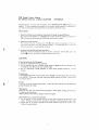
OPTONICA
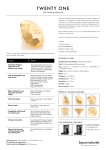
RX-1
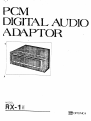
PCM Digital Audio Adaptor
The RX-1 unveils a completely new audio era with a wide range
of features and unique, innovative ideas.
A Dream Unit for Adventurous
Audiophiles
S h a r p ' s a d v a n c e d d i g i t a l t e c h n o l o g y is b a c k e d u p b y i n n o v a t i v e
videotape.
T h i s e l i m i n a t e s noise w h i c h c o u l d v e r y o f t e n be
m i x e d w i t h t h e m u s i c signals a t t h e t i m e o f r e c o r d i n g .
Adaptable to Any Type of Video Cassette Recorder
T h i s has been c o m b i n e d w i t h its
Having adopted O p t i m u m C o n t r o l f u n c t i o n , the RX-1 permits
sophisticated audio system expertise, well demonstrated in t h e
y o u t o search f o r t h e ideal m a t c h i n g p o i n t , best s u i t e d t o a n y
semiconductor technology.
t y p e o f v i d e o cassette r e c o r d e r , V H S o r B e t a . T h i s means t h a t
O P T O N I C A series.
N o w , O P T O N I C A is a n n o u n c i n g a n e w a u d i o e r a w i t h t h e i n
t r o d u c t i o n o f a dream u n i t - PCM digital audio adaptor R X - 1 .
Throughout
its c o n t i n u o u s ,
relentless
efforts
in t h i s
field,
O P T O N I C A has d e v e l o p e d t h e v e r s a t i l e , c o m p a c t P C M a d a p t o r
w h i c h c a n easily be c o n n e c t e d t o a n y h o m e v i d e o .
its impressive
breakthrough
in d r o p - o u t p r o o f i n g
the
ingenious
u n i t promises y o u spectacular
sound
quality
anytime, anywhere.
T h e a d a p t a b i l i t y level is c o n v e n i e n t l y d i s p l a y e d o n L E D i n d i
cators f o r y o u r q u i c k , accurate reference.
Featuring
capability,
t h e R X - 1 is t h e ideal s o l u t i o n t o " a n a l o g " a u d i o barriers t h a t
OPTONICA's Unique Drop-Out Proof System with
99.995% Perfection
c r i t i c a l a u d i o p h i l e s have l o n g been c o n f r o n t e d w i t h .
O P T O N I C A , b y f u l l y utilizing a sophisticated m e m o r y func
T h e P C M (Pulse C o d e M o d u l a t i o n ) s y s t e m sets a u d i o t e c h n o l
tion,
ogy o n a c o m p l e t e l y
accurate r e p r o d u c t i o n o f the original s o u n d .
analog audio.
new course, well b e y o n d
conventional
I t is t h e s y s t e m w h i c h c o n v e r t s a n a l o g signals
i n t o d i g i t a l signals f o r s t o r i n g t h e d a t a o n t h e v i d e o t a p e .
sound
into
signals are m i c r o s c o p i c a l l y d i v i d e d a n d t h e n
either
First,
encoded
1 (presence) o r 0 (absence) a n d r e c o r d e d
onto
has d e v e l o p e d
a superb
drop-out
system f o r d u t i f u l ,
Necessary d a t a
f o r d r o p - o u t p r o o f i n g are i n p u t a t t h e t i m e o f r e c o r d i n g .
Then
a t t h e t i m e o f p l a v i n g , c o r r e c t i o n is d o n e t o near p e r f e c t i o n .
T h e r e s u l t is a s t u n n i n g 9 9 . 9 9 5 % c o r r e c t i o n c a p a b i l i t y .
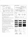
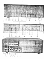
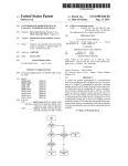
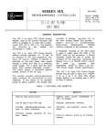
The way to record or reproduce on PCM
Blocks of the PCM unit
Digital output
Clock
generator
I nput
Recording
PCM unit
Video cassette recorder
Digital output
Reproduction
-|
z_
Memories
O *<§
Memories
[*
Error
correction
D/Aconverter
Low pass
filter
Reproduction
Speakers
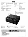
Compact and Light, Culmination of Modern Design
ing
Video cassette recorder
PLL
Error
Data check
° 006 O
O 000 O T * 00
Amplifier-
Redundancy
Audio
Audio output
PCM unit
A/Dconverter
Recording
H
Video cassette
recorder
Sample
and hold
Outputs
Microphones
Low pass
filter
TV
generator
Data formats
U n l i k e t h e general c o n c e p t t h a t PCM a d a p t o r s are b u l k y and
h e a v y , O P T O N I C A ' s R X - 1 is as c o m p a c t as a stereo a m p l i f i e r ,
15.5
kg.
Sharp's i n n o v a t i v e
Digital
semiconductor
Signals
t e c h n o l o g y has changed t h e w h o l e c o n c e p t .
Video
signal
Sample
and hold
Recorded
tape
Reproduction
Stunning 90dB Dynamic Range
VCR
D i g i t a l r e c o r d i n g s y s t e m means v e r y l o w d i s t o r t i o n a n d noise,
r e s u l t i n g in a s t u n n i n g 9 0 d B d y n a m i c r a n g e , t h a n k s t o 1 4 - b i t
Recorded
tape
Reproduced
wave
Data
(Error)
[£> o i o o i io] C)
D/A
only
Memories
weighing
Recording
Correction
A u d i o signals
quantizing.
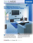
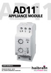
Extra High Fidelity Recording and Playback
Because t h e a u d i o signals are c o n v e r t e d i n t o pulse codes f o r
Playback waveform of 10 kHz
Cassette t a p e d e c k
O p e n reel t a p e d e c k
P C M system
r e c o r d i n g and p l a y b a c k , t h e s o u n d signals are n o t a f f e c t e d b y
r o t a r y mechanisms characteristic t o analog systems. T h e result
is
an
extremely
high
fidelity
in
recording
and
playback,
b e y o n d any possibilities o f the analog system.
Accurate, Easy-to-Read LED Level Meter
Playback waveform of silent portion (50 dB or 300 times
Cassette t a p e d e c k
O p e n reel t a p e d e c k
magnification on the scope)
P C M system
2 8 L E D level m e t e r o n o n e c h a n n e l p e r m i t s precise r e c o r d i n g
levels.
Easy to Connect to Various Kinds of Equipment
In a d d i t i o n t o P I N j a c k s , t h e u n i t i n c l u d e s c a n n o n c o n n e c t o r s
a n d M t y p e c o n n e c t i n g j a c k s , f o r easy c o n n e c t i o n o f t h e R X - 1
w i t h various kinds o f e q u i p m e n t .
Harmonic Distortion
Cassette t a p e d e c k
O p e n reel t a p e d e c k
P C M system
Wow and flutter
Cassette t a p e d e c k
O p e n reel t a p e d e c k
P C M system
Special Control for Precise Adaptability of PCM
Adaptor to Videotape.
Jack for Digital Direct Dubbing.
Other features
*
Mike mixing.
*
*
Headphone jack.
G o l d plated PIN iacks.
RX-1
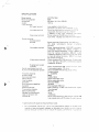
Specifications
Power Source:
AC220V, 50Hz [ A C 100V, 5 0 / 6 0 H z ] *
Wow & flutter:
Below measurability
Dimensions:
4 3 0 ( W ) x 141 ( H ) x 3 6 0 ( D ) m m
Harmonic distortion:
0 . 0 3 % (1 k H z )
Weight:
1 5 . 5 kg
D y n a m i c range:
90 dB
Recording format:
PCM
Transmission channels:
2 channels
r e c o r d i n g in
PAL
Reproducing frequency
standard
range:
T V signals [ N T S C s t a n d a r d ]
DC - 20 kHz
Others:
Line i n p u t jack
Line o u t p u t jack
Sampling frequency:
Number of
44.100 kHz [44.056 kHz]
Headphone jack
V i d e o i n p u t / o u t p u t jack
quantizing bit:
Data transmission rate:
Error correction
capability:
Crosstalk:
14-bit
'
2.625 Mbps [2.643 Mbps]
External synchronized
99.995%
*
M o r e t h a n 6 0 d B (1 k H z , 1 0 k H z )
Below measurability
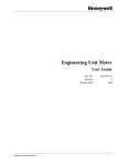
Power Switch
©
©
Headphone J ack
Power Indicator
o
Playback Indicator
©
Record Indicator
©
©
©
©
input/out
p u t jack
Level v a r i a t i o n :
o
D i g i t a l signal i n p u t / o u t p u t j a c k
D u b b i n g jack
Note: Information in [ j parentheses is for NTSC
standard.
The manufacturer reserves the right to vary specifica
tions, design, or use alternative materials as my be
deemed necessary or desirable at any time, any such
change or variation being of a kind as not to reduce
quality, performance or appearance.
PCM Tape Indicator
LED Level Indicator
©
Line Output Level Control
Anti-Digital Dubbing Indicator
MIC Input Jack
©
Line Input Level Control
Mode (Record/Play) Switch
©
©
Error Correction Signal
©
Indicators
Error Monitor Switch
Optimum Indicators
Headphone (Volume) Control
MIC Input Level Control
O p t i m u m Control
Bezugsquellennachweis
SHARP ELECTRONICS (EUROPE) GmbH.
SonninstraBe 3, 2000 Hamburg 1, F.R. Germany
Tel: (040) 28511 Telex: 2161867 HEEG D
Telegram: SHARPEUROPA HAMBURG
SHARP CORPORATION
OSAKA, JAPAN
CABLE ADDRESS: LABOMET OSAKA
TELEX: 63428 LABOMET A-D
'79 © S H A R P CORP. (8F2E) Printed in Japan
PCM
DIGITAL AUDIO
ADAPTOR
M O D E L
RX-1H
OPTONICA
OPTONICA
PCM DIGITAL AUDIO ADAPTOR
RX-1 H
CONTENTS
Contents
1
Features . . .
. . .
Caution
2
Controls and F u n c t i o n s
3 —4
Playback
.
.5
O p t i m u m Control
.6
Recording
Dubbing
2
6
x
.... . . . . . . . . . . . . . . . . . . . . . .
Connections
7
. 8 -
13
Specifications.
14
Troubleshooting
15
Note:
Audio-visual
material
may
consist
of c o p y r i g h t e d w o r k s w h i c h must not
w i t h o u t the a u t h o r i t y o f t h e o w n e r o f the c o p y r i g h t .
Please refer to r e l e v a n t l a w in y o u r c o u n t r y .
recorded
PCM Digital Audio Adaptor
RX-1KPCM DIGITAL AUDIO ADAPTOR
Congratulations!
adaptor.
OPTONICA
Y o u are n o w t h e o w n e r o f t h e O P T O N I C A R X - l H P C M d i g i t a l audso
T o f u l l y a p p r e c i a t e t h e b e n e f i t o f this q u a l i t y a u d i o p r o d u c t , i t is advised t h a t
y o u read a n d t h o r o u g h l y u n d e r s t a n d this o p e r a t i o n a l m a n u a l b e f o r e using.
FEATURES
1 . Meets E I A J ( E l e c t r o n i c s I n d u s t r i e s A s s o c i a t i o n o f J a p a n ) s t a n d a r d ( 8 2 5 l i n e ) .
T h i s d i g i t a l a u d i o a d a p t o r is m a n u f a c t u r e d t o m e e t t h e E I A J s t a n d a r d arranged
f
or
6 2 5 line areas a n d c a n be used o n V H S , B e t a , a n d U - m a t i c f o r m a t s .
2. O p t i m u m c o n t r o l f u n c t i o n
This c o n t r o l
function
maintains
the
R X - iHat
the o p t i m u m
level w h e n used w i t h a n y v i d e o cassette r e c o r d e r .
playback
performance
It c o m p e n s a t e s f o r a m i n o r per
f o r m a n c e d e v i a t i o n i n v i d e o cassette r e c o r d e r s .
3. E q u i p p e d w i t h p r o f e s s i o n a l t y p e c o n n e c t o r s
B r o a d c a s t s t a n d a r d c o n n e c t o r s s u c h as c a n n o n
connectors
and PL-259 type
video
c o n n e c i ® s are used in a d d i t i o n t o p o p u l a r p h o n o c o n n e c t o r s .
CAUTION
A H i n t on Setting up the E q u i p m e n t
1. P o s i t i o n all e q u i p m e n t f o r easy o p e r a t i o n .
2 . D o n o t o p e r a t e t h e u n i t i n h u m i d , d u s t y areas o r e x p o s e t h e u n i t t o e x t r e m e h e a t .
A t e m p e r a t u r e o f 3 0 ° C o r b e l o w is r e c o m m e n d e d .
3 . Use
an
appropriate
voltage
regulator
i n areas w h e r e v o l t a g e f l u c t u a t i o n
is above
average.
Power Source
T h e r e c o m m e n d e d p o w e r s o u r c e f o r t h e u n i t is A C 2 2 0 V .
with AC220V.
D o n o t o p e r a t e the u n i t e x c e p t
O t h e r w i s e , e l e c t r i c a l f a i l u r e s a n d o t h e r hazards w i l l r e s u l t , i n c l u d i n g f i r e
and e l e c t r i c shocks.
Service
T h e r e are n o user-serviceable p a r t s inside,
I n case o f f a i l u r e , t a k e t h e u n i t t o t h e nearest
a u t h o r i z e d dealer f o r r e p a i r .
Maintenance
Clean t h e u n i t w i t h s o f t c l o t h a n d m i l d d e t e r g e n t .
Never apply a l c o h o l , paint t h i n n e r ,
o r other h a r m f u l chemicals.
These d i s t i l l a t e s w i l l smear t h e casing o r r e m o v e t h e p a i n t .
D e w P r o b l e m o n a v i d e o cassette r e c o r d e r
1. D o n o t o p e r a t e a v i d e o cassette r e c o r d e r i n areas w h e r e m o i s t u r e c o n d e n s a t i o n m i g h t
occur.
Moisture c o n d e n s a t i o n may o c c u r inside the u n i t after heating a c o l d r o o m .
2 . Please refer t o an o w n e r ' s m a n u a l o f t h e v i d e o cassette r e c o r d e r f o r f u r t h e r
mation on dew problems.
infor
CONTROLS AND FUNCTIONS
1. Power s w i t c h
Push i n the s w i t c h t o " o n " p o s i t i o n , and push it i n again t o " o f f " p o s i t i o n .
2. Headphone jack
Accepts any headphone w i t h 3-ohm impedance.
3. P o w e r i n d i c a t o r
L i g h t s u p when the p o w e r is " o n " .
4. Playback indicator
L i g h t s u p w h e n m o d e s w i t c h 1 2 is i n " p l a y " p o s i t i o n .
5. R e c o r d i n d i c a t o r
L i g h t s u p w h e n * m o d e s w i t c h 12 is in " r e c o r d " p o s i t i o n .
8. P C M T a p e i n d i c a t o r
T h e l a m p i n d i c a t e s t h e P C M T a p e ( s i m i l a r t o a v i d e o cassette tape) is b e i n g p l a y e d
back.
7. A n t i - D i g i t a l d u b b i n g i n d i c a t o r
S o m e P C M Tapes have a n t i - d u b b i n g signals t h a t i n t e r f e r e w i t h d i g i t a l d u b b i n g .
The
i n d i c a t o r s h o w s t h e e x i s t e n c e o f such signals o n t h e t a p e , a n d d u b b i n g is t h e r e f o r e
inoperative,
8. f r r r o r c o r r e c t i o n signal i n d i c a t o r s
These s h o w t h e level o f signal c o r r e c t i o n b e i n g m a d e o n t h e p r e r e c o r d e d P C M t.tp<:s.
A " s i n g l e " l a m p w i l l l i g h t up w h e n signal c o r r e c t i o n is m a d e o n c e .
If t w o <«*jna!
c o r r e c t i o n s are b e i n g m a d e , b o t h the " s i n g l e " a n d " d o u b l e " l a m p s .v--!i l i g h t
. .)
9. O p t i m u m i n d i c a t o r s
The
f e w e r t h e i n d i c a t o r s are o n , t h e b e t t e r t h e p l a y b a c k c o n d i t i o n w h e n u s i n g a
PCM
Tape.
When
several
indicators
are
on,
turn
the o p t i m u m
control
knob
clockwise or counter-clockwise to o b t a i n the best c o n d i t i o n .
10.
L E Q level i n d i c a t o r s
R e c o r d i n g o r p l a y b a c k levels o n each c h a n n e l are m o n i t o r e d .
f r o m the conventional method.
Level s e t t i n g d i f f e r s
I t is r e c o m m e n d e d t h a t t h e average i n p u t level be set
a r o u n d \ — 9 d B ; never let t h e " o v e r " i n d i c a t o r l i g h t u p .
11.
M I C i n p u t jack
A c c e p t s l o w i m p e d a n c e m i c r o p h o n e s in r i g h t a n d l e f t c h a n n e l s .
12. Mode (Record/Play) switch
Select e i t h e r R e c o r d o r Play m o d e w i t h this s w i t c h .
13. E r r o r m o n i t o r s w i t c h ( T w o - w a y m o n i t o r s w i t c h )
Push
it
to
"source"
position
formance by headphones.
for
monitoring
both
recording and playback
per
" C h e c k " p o s i t i o n is f o r m o n i t o r i n g and c h e c k i n g t r a c k i n g ,
o p t i m u m c o n t r o l level, o r d r o p o u t s w h e n using a v i d e o cassette r e c o r d e r .
14.
Headphone volume control
Controls output
r e c o r d i n g level.
15.
level
for headphones.
Variable
volume
c o n t r o l does n o t
affect
L i n e o u t p u t level c o n t r o l
C o n t r o l s playback o u t p u t of the taped source.
when
using an a m p l i f i e r .
Level
o u t p u t level c o n t r o l o p e r a t i o n .
indicators
Set t h e c o n t r o l k n o b t o m a x i m u m
show
the
f i x e d o u t p u t , regardless o f
16.
L i n e i n p u t level c o n t r o l
C o n t r o l s i n p u t level f r o m a h o m e s t e r e o s y s t e m o r a t a p e d e c k .
17.
M I C i n p u t level c o n t r o l
C o n t r o l s i n p u t level f r o m m i c r o p h o n e s .
18.
Optimum control
M a i n t a i n s t h e d i g i t a l a d a p t o r at o p t i m u m p l a y b a c k c o n d i t i o n w h e n used w• t h a n y
v i d e o cassette r e c o r d e r .
It c o m p e n s a t e s a m i n o r p e r f o r m a n c e d e v i a t i o n
in
-/ki^o
cassette r e c o r d e r s .
19.
Line i n p u t t e r m i n a l ( p h o n o jack)
C o n n e c t s R e c o r d o u t o r L i n e o u t t e r m i n a l s o f an a m p l i f i e r .
Never use this t e r m i n a l
and Line i n p u t terminal (21) (cannon t y p e connector) simultaneously
20.
1
Line o u t p u t t e r m i n a l ( p h o n o jack)
C o n n e c t s Tape* p l a y b a c k o r L i n e i n t e r m i n a l s o f an a m p l i f i e r .
21.
Line i n p u t terminal (cannon X L R - 3 - 3 1 type unbalanced connector)
Use t h i s t e r m i n a l f o r c o n n e c t i n g a m i c r o p h o n e m i x e r o r o t h e r p r o f e s s i o n a l
equipment.
N e v e r use t h i s i n p u t t e r m i n a l a n d L i n e i n p u t t e r m i n a l (19)
audio
( p h o n o jack)
simultaneously!
T h e n u m b e r t h r e e p i n is a h o t w i r e .
22.
Line o u t p u t terminal (cannon X L R - 3 - 3 2 t y p e unbalanced connector)
Use this t e r m i n a l f o r c o n n e c t i n g L i n e o u t p u t o f p r o f e s s i o n a l t y p e a m p l i f i e r s .
23.
Digital i n p u t / o u t p u t
Use
this
terminal
terminal
for
connecting
another
RX-lHdigital
adaptor's
input,'outout
t e r m i n a l w h e n d i g i t a l d u b b i n g is p e r f o r m e d b y u s i n g t w o R X - l l i j i g i t a i j t t a p t o r s a n d
t w o v i d e o cassette r e c o r d e r s .
24.
Video input terminal
Use
this t e r m i n a l
recorder.
f o r connecting the video o u t p u t terminal o f
a video
cassette
N e v e r use t h i s v i d e o i n p u t t e r m i n a l a n d P L - 2 5 9 t y p e v i d e o i n p u t t e r m i n a l
( 2 6 ) a t t h e same t i m e !
25.
Video output terminal
Use t h i s t e r m i n a l f o r c o n n e c t i n g t h e v i d e o i n p u t t e r m i n a l o f a v i d e o cassette r e c o r d e r .
N e v e r use t h i s t e r m i n a l a n d t h e P L - 2 5 9 t y p e
video o u t p u t
terminal
(27) simul
taneously!
26.
Video input terminal (PL-259 type connector)
Use t h i s t e r m i n a l f o r c o n n e c t i n g t h e P L - 2 5 9 t y p e v i d e o o u t p u t t e r m i n a l o f a v i d e o
cassette r e c o r d e r .
N e v e r use t h i s t e r m i n a l a n d an a d d i t i o n a l v i d e o i n p u t
terminal
(24) s i m u l t a n e o u s l y !
27.
Video o u t p u t terminal (PL-259 type connector)
Use t h i s t e r m i n a l f o r c o n n e c t i n g t h e P L - 2 5 9 t y p e v i d e o i n p u t t e r m i n a l o f a v i d e o
cassette r e c o r d e r .
N e v e r use t h i s t e r m i n a l a n d an a d d i t i o n a l v i d e o o u t p u t
terminal
(25) simultaneously!
28.
Dubbing output terminal
Use t h i s t e r m i n a l w h e n d u b b i n g is p e r f o r m e d b y using t h i s d i g i t a l a d a p t o r j n d
v i d e o cassette r e c o r d e r s .
two
Connect it t o the video i n p u t t e r m i n a l of the recording
v i d e o cassette r e c o r d e r .
29.
External sync o u t p u t terminal ( p h o n o jack)
C o n n e c t t o t h e e x t e r n a l sync i n p u t t e r m i n a l o f a v i d e o cassette r e c o r d e r .
30.
External sync o u t p u t terminal (PL-259 t y p e )
C o n n e c t t o t h e P L 2 5 9 t y p e e x t e r n a l s y n c i n p u t t e r m i n a l o f a video cassette r e c o r d e r .
4 -
PLAYBACK
R e f e r t o t h e o w n e r ' s m a n u a l f o r t h e o p e r a t i o n o f a v i d e o cassette r e c o r d e r .
v
1. M a k e c o n n e c t i o n s as i l l u s t r a t e d : see d i a g r a m [2]—[3J2. Push " o n " t h e p o w e r s w i t c h { 1 ) .
3. S w i t c h t h e m o d e selector t o " p l a y " p o s i t i o n .
4.
L o a d a P C M t a p e i n t o a video cassette r e c o r d e r .
5. S e t t h e v i d e o cassette r e c o r d e r ' s t r a c k i n g c o n t r o l k n o b t o a u t o p o s i t i o n , or t o the
c e n t e r p o s i t i o n i f m a n u a l l y set.
6. C o n n e c t a h e a d p h o n e t o t h e h e a d p h o n e j a c k
7. P l a y b a c k
t h e v i d e o cassette r e c o r d e r
(2).
a n d set t h e e r r o r m o n i t o r s w i t c h
(two-way
monitor switch) t o " c h e c k " position.
8. A d j u s t o p t i m u m c o n t r o l b y m o n i t o r i n g o p t i m u m i n d i c a t o r s .
9. O b t a i n m a x i m u m t r a c k i n g c o n t r o l b y l i s t e n i n g t o t h e c h e c k i n g signals.
10. N o w , t h e tape Can be p l a y e d b a c k a n y t i m e .
•
D u r i n g o p t i m u m c o n t r o l o r t r a c k i n g c o n t r o l , t u r n d o w n t h e a m p l i f i e r v o l u m e a n d set
the m o n i t o r switch t o the " m o n i t o r " p o s i t i o n .
•
O n c e t h e i n i t i a l o p t i m u m c o n t r o l a n d t r a c k i n g c o n t r o l is a d j u s t e d , t h e r e is n o f u r t h e r
a d j u s t m e n t necesHry as l o n g as t h e v i d e o cassette r e c o r d e r is used.
•
A l w a y s use a r e l i a b l e v i d e o cassette r e c o r d e r i n e x c e l l e n t w o r k i n g c o n d i t i o n in o r d e r
to obtain m a x i m u m performance
f r o m the digital adaptor.
A l w a y s keep t h e v i d e o
heads c l e a n .
•
W h e n using a p r e r e c o r d e d P C M t a p e , m a k e sure i t c o m p l i e s w i t h t h e P C M r e c o r d i n g
standard.
Error Monitor Switch (Two-way Monitor Switch)
Source Position
•
R e c o r d i n g a n d p l a y b a c k c o n d i t i o n s are m o n i t o r e d b y h e a d p h o n e s w h e n t h e s w i t c h is
in " s o u r c e " p o s i t i o n .
•
When the switch
is i n " c h e c k " p o s i t i o n , t h e h e a d p h o n e s p i c k u p t h e i n t e r m i t t e n t
signal s o u n d t o i n d i c a t e w h e t h e r t h e o p t i m u m c o n t r o l o r t r a c k i n g c o n t r o l is p r o p e r l y
set. T h e b e t t e r t h e c o n d i t i o n , t h e less a u d i b l e t h e signal b e c o m e s .
U s u a l l y , set t h e t r a c k i n g c o n t r o l t o " a u t o " p o s i t i o n .
W h e n t h e signal s o u n d b e c o m e s
q u i c k a n d c l e a r l y a u d i b l e , t h e p l a y b a c k c o n d i t i o n is poor. Proceed t o set t h e t r a c k i n g
c o n t r o l manually t o obtain the o p t i m u m playback c o n d i t i o n .
F o r m a n u a l settings,
follow the instructions below:
t . L i s t e n c a r e f u l l y t o t h e signal s o u n d . C o u n t a n u m b e r o f signals a u d i b l e w i t h i n a p e r i o d
o f five seconds.
signal i n t e r v a l .
T u r n i n g o f a t r a c k i n g c o n t r o l k n o b w i l l e i t h e r increase or decrease
Set t h e k n o b w h e r e t h e least a m o u n t of signal is a u d i b i e w i t h i n a
p e r i o d o f f i v e seconds. R e p e a t this several t i m e s t o o b t a i n m a x i m u m t r a c k i n g c o n t r o l .
W h e n t h e t r a c k i n g c o n t r o l k n o b is t u r n e d , t r a c k i n g is m o m e n t a r i l y d i s t u r b e d .
When
making a n a d j u s t m e n t , w a i t until t h e t r a c k i n g is s t a b i l i z e d and n o c o n t i n u o u s signal
s o u n d is heard.
•
•
T h e signal s o u n d is o n l y r e p r o d u c e d b y t h e h e a d p h o n e t e r m i n a l (2) a n d i t w o n ' t be
r e p r o d u c e d t h r o u g h t h e speakers.
E v e r y t i m e a v i d e o cassette r e c o r d e r / v i d e o cassette tape is c h a n g e d , b e sure t o m a k e
tracking control and o p t i m u m control adjustments.
•
W h e n recording, push back the switch t o the " s o u r c e " position.
OPTIMUM CONTROL
T h i s c o n t r o l m a i n t a i n s t h e o p t i m u m p e r f o r m a n c e f r o m t h e d i g i t a l a d a p t o r even w h e n the
v i d e o cassette r e c o r d e r deviates f r o m n o r m a l p e r f o r m a n c e figures.
1. F i r s t , set t h i s k n o b t o t h e n o t c h e d " m i d d l e " p o s i t i o n .
2. O p t i m u m i n d i c a t o r s w i l l l i g h t u p w h e n a P C M Tape is p l a y e d b a c k .
i n d i c a t o r s w i l l l i g h t u p i f t h e p l a y b a c k c o n d i t i o n is f a v o u r a b l e ,
Less t h a n :-vo
r
w ^ e n he
;
c o n d i t i o n is p o o r , several i n d i c a t o r s w i l l l i g h t u p t o s h o w t h a t the o p t - m u m c o r : r e ;
requires readjustment.
}
A d j u s t t h e k n o b so t h a t t h e fewest tamps w
be si! - i - v r / i t r c
•
R e a d j u s t the k n o b each t i m e a v i d e o cassette r e c o r d e r / c a s s e t t e t a p e is c h a n g e d .
•
Since the p e r f o r m a n c e c h a r a c t e r i s t i c s o f each v i d e o cassette r e c o r d e r m a y
arv
m a y be cases w h e n t w o t o t h r e e i n d i c a t o r s l i g h t u p even if the play sack c o r d . : cr. 3
very g o o d .
A l l o p t i m u m i n d i c a t o r s m a y l i g h t u p r i g h t a f t e r a video cassette ' e c j r c : - : ' s
h o o k e d t o the digital adaptor.
Just playback
T h i s does n o t i n d i c a t e the m a c h i n e in m a l f u n c f ~--r-. -3.
t n e P C M T a p e , a n d w a i t u n t i l t h e P C M Tape i n d i c a t o r is o n
c^fcre
making any adjustment.
RECORDING
R e f e r t o t h e o w n e r ' s m a n u a l f o r the o p e r a t i o n o f a v i d e o cassette r e c o r d e r .
1. M a k e c o n n e c t i o n s as i l l u s t r a t e d : see d i a g r a m [ T j - [ 2 ] .
2. Push " o n " t h e p o w e r s w i t c h ( 1 ) .
3. S w i t c h m o d e s e l e c t o r ( 1 2 ) t o " r e c o r d " p o s i t i o n .
4 . A d j u s t t o p r o p e r r e c o r d i n g level b y t u r n i n g t h e L i n e i n p u t c o n t r o l ( 1 6 ) k n o b o r M I C
i n p u t c o n t r o l ( 1 7 ) k n o b . Set the level i n d i c a t o r ( 1 0 ) f o r visual c h e c k i n g o f i n p u t level.
5. L o a d t h e v i d e o t a p e .
Clear the t a p e c o u n t e r t o zero o n t h e v i d e o cassette r e c o r d e r ,
Press t h e r e c o r d b u t t o n .
•
Since i t takes several seconds f o r t h e v i d e o cassette r e c o r d e r t o be s t a b i l i z e d , .73<t
several seconds b e f o r e s t a r t i n g t o r e c o r d .
•
W h e n t h e m i c r o p h o n e is n o t used, t u r n t h e M I C i n p u t c o n t r o l k n o b t o " 0 " p o s i t i o n .
A l w a y s use r e l i a b l e v i d e o cassette r e c o r d e r s i n an e x c e l l e n t w o r k i n g c o n d i t i o n s t o
obtain m a x i m u m recording performance f r o m the digital adaptor.
A l w a y s keep the
v i d e o heads c l e a n .
•
•
W h e n r e c o r d i n g , P C M T a p e ( o p t i o n a l l y a v a i l a b l e ) is r e c o m m e n d e d .
W h e n r e c o r d i n g is c o m p l e t e d , let t h e v i d e o cassette r e c o r d e r r u n f o r several seconds
b e f o r e disengaging t h e r e c o r d b u t t o n .
•
W h e n r e c o r d i n g r i g h t a f t e r t h e p r e v i o u s l y r e c o r d e d p r o g r a m m e s , let the v i d e o cassette
r e c o r d e r r u n in p l a y b a c k m o d e f o r several seconds b e f o r e pressing t h e r e c o r d b u t t o n .
P r o p e r R e c o r d i n g Level
Set t h e average r e c o r d i n g level at a b o u t — 9 d 3 .
1. C h e c k the level i n d i c a t o r s a n d a d j u s t the L i n e i n p u t c o n t r o l ( 1 8 ) or M I C i n p u t c o n t r o l
( 1 7 ) t o set the average r e c o r d i n g level as close as possible t o - 9 d 3 f o r 3
normal recording.
2. S e t t i n g o f the average r e c o r d i n g level at m o r e t h a n — 9 d B p r o d u c e s g o o d P C M r e c o r d
!
ing results. B u t N E V E R a l l o w the " O v e r " level i n d i c a t o r t o l i g h t u p
3. V a r y the average r e c o r d i n g level b e l o w o r over —9dB d e p e n d i n g o n the t y p e o f r e c o r d
ing.
•
Set peak r e c o r d i n g level b e l o w t h e " O V E R " l e v e l , b u t d o n o t set it t o o l o w ; o t h e r w i s e
a p o o r S / N r a t i o w i l l result.
DUBBING
T h e r e are b a s i c a l l y t h r e e m e t h o d s - o f d u b b i n g using t h i s d i g i t a l a u d i o a d a p t o r .
D u b b i n g Can Be P e r f o r m e d Using T V Signals
1. Push " o n " t h e p o w e r s w i t c h .
2. S w i t c h the m o d e s e l e c t o r t o p l a y p o s i t i o n ?
3. P a y b a c k the v i d e o cassette r e c o r d e r , (refer t o P L A Y B A C K s e c t i o n )
4 . Set t o r e c o r d m o d e o n t h e v i d e o cassette r e c o r d e r , (refer to P L A Y B A C K s e c t i o n )
5. D u b b i n g is n o w in process.
•
A d j u s t i n g P l a y b a c k o u t p u t c o n t r o l ( 1 5 ) , L i n e i n p u t c o n t r o l ( 1 6 ) , or M I C i n p u t c o n t r o l
( 1 7 ) does n o t a f f e c t r e c e o r d i n g level.
Analog Dubbing
1. Push o n the p o w e r s w i t c h ( 1 ) .
2
Switch
the
nlode
selector
(12)
to
"play"
position
on
the
playback
digital
audio adaptor.
3. S w i t c h
the m o d e selector (12) t o " r e c o r d " p o s i t i o n o n the recording digital
audio
adaptor.
4 . P l a y b a c k t h e s o u r c e ( p l a y b a c k ) v i d e o cassette r e c o r d e r , ( r e f e r t o P L A Y B A C K s e c t i o n )
5
Set t h e r e c o r d m o d e o n t h e r e c o r d i n g v i d e o cassette r e c o r d e r , (refer t o
PLAYBACK
section)
6. N o w d u b b i n g is i n process.
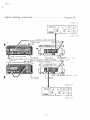
Digital D u b b i n g
1 . R e f e r t o d i a g r a m 16] f o r c o n n e c t i o n s .
2 . O p e r a t i o n p r o c e d u r e is i d e n t i c a l t o t h e a n a l o g d u b b i n g .
*
T h e r e m a y be c e r t a i n cases w h e n u s i n g the T V signal w i l l n o t p r o d u c e g o o d d u b b i n g
results.
T h i s is because t h e r e are m i n o r p e r f o r m a n c e d e v i a t i o n s a m o n g v i d e o cassette
recorders
a n d v i d e o cassette t a p e s .
If this is t h e case, p e r f o r m
d u b b i n g as e x p l a i n e d earlier.
7
analog or
digital
or live r e c o r d i n g s
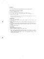
Diagram 1
s
R e c o r d i n g from a r e c o r d album. F M b r o a d c a s t o r tape r e c o r d e r ,
and p l a y b a c k
:
:
D
i
a
g
r
a
m
2
Line
input
Cannon
c o n nee t o r
Microphone
output
in i x e r
cable
Amplifier
Line input
Lino out pu t
Video input
Coaxial cables provided V i d e o
Video output
output
Video i n p u t
RX-IH
VTR
PQ.ver
;jourco
V I DhlO
IN
VI. Dh;0 OUT
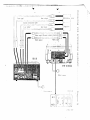
Diagram 3;
. P o w e r s o u roe
VC-6300
Connecting with professional equipment:
Line
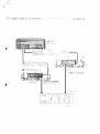
T V s i g n a l dubbing c o n n e c t i o n :
-
Diagram 4
Analog dubbing c o n n e c t i o n :
Diagram 5"
D i g i t a l dubbing
connection:
D i a g r a m _6j
SPECIFICATIONS
Power source:
A C 220V, 50Hz
Power c o n s u m p t i o n :
38 W
Dimensions:
4 3 0 (W) x 141 (H) x 3 6 0 (D)
Weight:
15,5 kg
Input terminals:
MIC input terminal:
L o w impedance microphone;
M i n i m u m i n p u t l e v e l , 3 m V ( — 4 8 d B m ) or k>ss.
Line input t e r m i n a l :
Phone c o n n e c t o r / c a n n o n connector X L R - 3 - 3 1
u n b a l a n c e d ; M i n i m u m i n p u t level, i G O m V
'(—18dBm)
Video input terminal:
or
less; I n p u t
impedance, 47k
ohms.
Phono connector/PL-259 type connector,
I n p u t l e v e l , 1.0 1 0 . 2 V p - p { 7 5 o h m s t e r m i n a t i o n ! .
Output terminals:
Dubbing output
terminal:
*
P h o n o c o n n e c t o r ; O u t p u t level, 1 . 0 1 0 . 2 V p - p
(75
ohms
termination);
Output
impedance,
75 ohms.
Line o u t p u t t e r m i n a l :
Phone
connector/cannon
unbalanced;
more
for
more
for
Output
phono
XLR3-32
level,
5G0mV
connectors,
cannon
1.23V
connectors;
impedance; Matching
loaded
connector,
(-4dSm)
(t-4dBm}
600-ohm
or
or
loaded
i m p e d a n c e , 10k o h m s
or more for p h o n o connector,
600
ohms
or m o r e
for cannon connectors.
Video output terminal:
P h o n o c o n n e c t o r / P L - 2 5 9 c o n n e c t o r . O u t p u t level,*
1.0 t
0.2
Vp-p
(75 ohms
termination}; Output
impedance, 75 ohms.
External sync o u t p u t
terminal:
Phono connector/PL-259
connectors; T T L
Digital i n p u t / o u t p u t t e r m i n a l :
D - t y p e s u b c o n n e c t o r ; T T L level.
A u x i l i a r y V i d e o Cassette r e c o r d e r :
S h a r p V C - 6 3 0 0 { V H S f o r m a t ) ; Seta f o r m a t ;
Frequency response:
2 — 20,000Hz
level.
U-matic format.
•
D y n a m i c range:
90dB
Harmonic distortion:
0 . 0 3 % (1kHz)
Wow & flutter;
B e l o w measurable value.
Level v a r i a t i o n :
B e l o w measurable value.
Crosstalk:
More than 60dB.
Error correction capability:
99.995%
Standard:
El A J standard ( 5 2 5 line)
Recording f o r m a t :
PCM recording
Transmission channels:
T w o channels.
Sampling frequency:
44.1kHz
Number of quantizing bit:
14-bit
Data transmission rate:
2.525Mops-
Accessories:
in 6 2 5
line standard T V
signals.
Phono type connecting cable; Phono type/PL-259
Type c o a x i a l c a b l e x 2 ( 7 5 o h m s } ; O w n e r ' s m a n u a l .
* S p e c i f i c a t i o n s are s u b j e c t t o change w i t h o u t n o t i c e .
*
T h e m a n u f a c t u r e r reserves t h e r i g h t t o v a r y s p e c i f i c a t i o n s , d e s i g n , o r use a l t e r n a t i v e
m a t e r i a l s as m a y b e d e e m e d necessary o r desirable at any t i m e , any such change o r
v a r i a t i o n b e i n g o f a k i n d as n o t t o r e d u c e t h e q u a l i t y , p e r f o r m a n c e or
appearance.