1
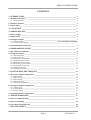
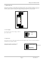
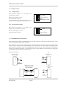
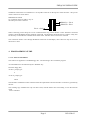
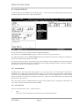
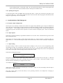
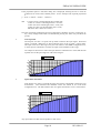
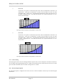
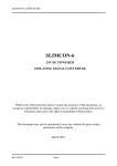
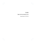
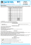
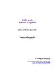
FREQCON USERS GUIDE
FREQCON
FREQUENCY TO ANALOGUE
CONVERTER
Whilst every effort has been taken to ensure the accuracy of this document, we accept no responsibility for
damage, injury, loss or expense resulting from errors or omissions, and reserve the right of amendment without
notice.
Industrial Interface Research Ltd 2002
This document is issued by Industrial Interface Research Ltd and may not be reproduced in any way without the
prior written permission of the company.
IIG-9509-03
Page 1
FREQCON USERS GUIDE
CONTENTS
1. INTRODUCTION_________________________________________________________ 4
1.1 Hardware Features ____________________________________________________________ 4
1.1.1 Isolation Details ____________________________________________________________________ 4
1.2 Software Features______________________________________________________________ 4
1.3 Smart LED ___________________________________________________________________ 5
2. UNPACKING ____________________________________________________________ 5
3. WIRING DETAILS _______________________________________________________ 6
3.1 Power Supply _________________________________________________________________ 6
3.2 Input Sensor __________________________________________________________________ 6
3.3 Analogue Output ______________________________________________________________ 7
3.3.1 Voltage Output _____________________________________________Error! Bookmark not defined.
3.3.2 Current Source Output _______________________________________________________________ 7
3.4 Communication Connection _____________________________________________________ 7
4. PROGRAMMING GUIDE__________________________________________________ 8
4.1 PC Software Installation ________________________________________________________ 8
4.2 Using the Software _____________________________________________________________ 9
4.2.1 The Main Menu ____________________________________________________________________ 9
4.2.2 File Operations _____________________________________________________________________ 9
4.2.3 Editing the Configuration ____________________________________________________________ 10
4.2.4 Programming the Freqcon ___________________________________________________________ 10
4.2.5 Reading from the Freqcon ___________________________________________________________ 11
4.2.6 Monitoring Current Values___________________________________________________________ 11
4.2.7 Printing the Configuration ___________________________________________________________ 11
4.2.8 Additional Features ________________________________________________________________ 11
4.2.9 Quitting the Program _______________________________________________________________ 12
5. CONFIGURING THE FREQCON __________________________________________ 12
5.1 Frequency Input Configuration _________________________________________________ 12
5.1.1 Input Options _____________________________________________________________________
5.1.2 Input Scaling______________________________________________________________________
5.1.3 Input Ranging _____________________________________________________________________
5.1.4 Input Processing ___________________________________________________________________
5.1.5 Advanced Input Options_____________________________________________________________
12
12
13
13
15
5.2 Analogue Output Configuration _________________________________________________ 16
5.2.1 Output Types _____________________________________________________________________ 16
5.2.2 Output Modes _____________________________________________________________________ 16
5.2.3 Output Scaling ____________________________________________________________________ 17
5.3 Communications Configuration _________________________________________________ 17
6. TROUBLESHOOTING ___________________________________________________ 17
6.1 Unit is Completely Dead _______________________________________________________ 17
6.2 Incorrect Reading_____________________________________________________________ 18
6.3 Unit Won’t Respond to PC _____________________________________________________ 18
7. SPECIFICATIONS ______________________________________________________ 18
Page 2
IIG-9509-03
FREQCON USERS GUIDE
7.1 Frequency Input_______________________________________________________________18
7.1.1 Input Types and Specification_________________________________________________________ 19
7.1.2 Temperature Stability _______________________________________________________________ 19
7.2 Analogue Output ______________________________________________________________19
7.2.1 Maximum Output Values ____________________________________________________________ 19
7.2.2 Temperature Stability _______________________________________________________________ 19
7.3 Time Response ________________________________________________________________19
7.4 Communications Channel_______________________________________________________20
7.5 Isolation _____________________________________________________________________20
7.6 Power Requirements ___________________________________________________________20
7.7 Dimensions ___________________________________________________________________20
7.8 Mountings____________________________________________________________________20
IIG-9509-03
Page 3
FREQCON USERS GUIDE
1. INTRODUCTION
1.1 Hardware Features
The FREQCON is an Intelligent Analogue to Frequency Converter. It supports a wide range of signal inputs,
from hall effect transducer signals to ±24V signals. It also produces 2 types of analogue output, voltage and mA
source.
The instrument has a choice of either an RS232 or an RS485 communication port. If the RS485 option is fitted,
the unit can be multi-dropped allowing up to 32 units to share the same communications line.
The instrument is packaged in a very compact enclosure which can be mounted on standard DIN-rail.
1.1.1 Isolation Details
The Freqcon has full 3 port isolation of 500V between the Input Stage, Processing/Comms, Output Stage and
PSU. This is illustrated below:
RS232 /RS485
Communications
Universal
Input
Stage
Configurable
Output
Stage
µP
Input Supply
µP Supply
Output Supply
24 V Input
1.2 Software Features
The unit can be totally configured with very easy to use PC software, and there is no need to set links or switches
within the unit.
The instrument can re-scale the input signal, average it, or linearise it. This value can then be re-transmitted on
the output, clipped or inverted. The maximum and minimum values of the signal are stored and can be accessed
through the communications channel or transmitted on the analogue output.
The system communicates using the standard Modbus ASCII protocol, allowing it to communicate with a range
of SCADA packages.
Page 4
IIG-9509-03
FREQCON USERS GUIDE
1.3 Smart LED
The unit has a Smart LED status indicator, which has four modes of operation.
•
One flash every 2 seconds
This indicates that the unit is healthy and functioning normally.
•
Quick Flashing
An error has occurred.
This could simply be a power glitch. If it is, the unit will still be functioning correctly.
However if the unit is powered down for 5 seconds and then the power is re-applied, and the quick
flashing continues, the unit has developed a fault.
•
LED On Continuously
The Unit is malfunctioning.
•
LED Off Continuously
Either the power supply is not connected properly or the unit is faulty.
2. UNPACKING
The instrument should be carefully inspected for signs of damage which may have occurred in transit. In the
unlikely case that damage has been sustained, please retain all packaging for our inspection and contact your
supplier immediately.
The instrument comes with the following items as standard:
1
Freqcon Smart Frequency to Analogue Converter
If Communications Cable is Ordered:
1
PC Communications Cable terminated with 25 Way D-Type Connector
If PC software ordered:
1
3.5” Floppy Disc containing Smart PC Software.
If Full User Manual Ordered:
1
IIG-9509-03
A4 Bound User Manual.
Page 5
FREQCON USERS GUIDE
3. WIRING DETAILS
The Freqcon is housed in a compact DIN rail mounting enclosure, with 12 terminals, arranged in 4 rows of 3
terminals. Two rows are at the top of the front panel and 2 rows are at the bottom. The sensor input terminals are
on the second from bottom row and the power supply and analogue outputs are on the top terminals.
1
4
5
6
7
8
9
10
2
3
11
12
3.1 Power Supply
The connection for the Power Supply is made to
pins 1 and 2 as shown.
Gnd
+24V
1
2
3
3.2 Input Sensor
The Freqcon can accept a wide range of signal levels for the frequency input. However, the same terminals are
used whatever type of signal is applied.
The Frequency Signal is connected to pin 9.
The Signal Ground is connected to pin 7.
9
Frequency Signal
8
7
Page 6
Signal Ground
IIG-9509-03
FREQCON USERS GUIDE
3.3 Analogue Output
3.3.1 Voltage Output
The Freqcon can produce a 0 to 10V output. The
connections are shown.
The 0 to 10V signal is on Pin 5.
The Output Gnd is on Pin 4.
A Wire Link MUST be placed between pins 5 and
6, otherwise the voltage output will remain at 0V.
4
Gnd
5
0-10Volt
6
Wire Link
3.3.2 Current Source Output
The Freqcon can produce a 0 to 20mA output
signal. The connections are as shown.
4
Gnd
5
The 0 to 20mA signal is on Pin 6.
The Output Gnd is on Pin 4.
6
0-20mA
3.4 Communication Connection
The Communication signals are terminated on a 10 way IDC connector on the top face of the enclosure. There
are 2 types of signal available RS232 or RS485.
The standard unit is able to produce RS232 signals. However the signals from this connector are not RS232 and
must be used in conjunction with the standard Freqcon Communications cable which produces the RS232 signals
ready for direct connection to a PC. The Communications cable has a 10 way IDC connector at one end and a 25
way D-Type connector at the other. It may also be necessary to use an adapter to convert the 25 way D-type into
a 9 way D-type for connection to some serial ports.
This is illustrated here:
PC
25 Way D-Type
Male
Unicon Cable
25 Way D-Type
Female
Tx
Rx
2
3
Tx
7
Gnd
Rx
Gnd
2
2
Rx
3
3
Tx
5
Gnd
IIG-9509-03
Gnd
Gnd
Page 7
7
PC
9 Way D-Type
Male
Adapter 25 to 9 Way
2 and 3 Swapped
Male to Female
7
2
3
2
3
5
FREQCON USERS GUIDE
The RS485 connections are terminated on a 10 way IDC connector on the top face of the enclosure. The pin out
of this connector is shown below:
IMPORTANT NOTE:
No connection must be made to any of
the other pins on this connector.
1
2
RS485 A - Pin 4
RS485 B - Pin 6
Pin 9 - Gnd
When connecting several Freqcons on one communications loop, all the RS485 A lines should be connected
together, and all the RS485 B lines should be connected. The Gnd lines should be used as a shield. It may also
be necessary to terminate the communications cable with a 120 ohm resistor across lines A and B.
The connection made to a PC through the RS485 connection is half-duplex, that is data can only travel in one
direction at a time.
4. PROGRAMMING GUIDE
4.1 PC Software Installation
The software is supplied on a standard floppy disc. The first thing to do is install the program.
All commands below are followed by the <ENTER> key.
Insert the floppy disc,
At the C: prompt type:
a:
At the A: prompt type:
install
The automatic installation routine will then install the required files onto the hard disc in a directory specified by
the user.
This working copy should be the only one that is used, with the master disc stored safely, in case the software
needs
to be re-installed.
Page 8
IIG-9509-03
FREQCON USERS GUIDE
4.2 Using the Software
To run the software type FREQCON at the DOS prompt. A title screen will be displayed and pressing any key
will then display the main screen. This is shown below:
The top line shows the version number and the configuration filename.
The bottom line is the HELP LINE which gives advice on what the current option means.
The 2nd from bottom line is the STATUS LINE which gives information on the active COM port, the address to
be used for communicating, and the current date.
The screen is split left to right. The left side of the screen holds the current configuration for the input, and the
right side of the screen holds the current configuration for the analogue and digital outputs. These are divided by
the Main Menu which is in the middle of the screen.
4.2.1 The Main Menu
The Main Menu is the central point of the program. It is very easy to use. The current option on the menu is
highlighted. Any other option can be selected by using the up or down cursor keys to select the required option
or by pressing the highlighted capital letter in the required option. Once the highlight bar is on the required
option, the function is activated by pressing the <Enter> key. There are several other menus in the software and
they all work in the same way.
If the user needs to return to the Main Menu at any point in the program, then by pressing the <ESCAPE> key
one or more times the main menu will become available.
4.2.2 File Operations
There are 3 File operations, ‘New’, ‘Open’ and ‘Save’.
•
New
Clears the current configuration and sets all the items to their default values.
IIG-9509-03
Page 9
FREQCON USERS GUIDE
•
Open
Prompts the user to enter a filename from which to load a configuration.
•
Save
Prompts the user to enter a filename so that the current configuration can be saved to disk.
The current filename is shown in the upper right hand corner of the display. After the filename an asterisk ‘*’
may appear; this signifies that the configuration has been modified and not saved to disk. The configuration file
will always be saved with an extension of ‘.FN1’, even if another extension is specified in the ‘Save’ dialog box.
4.2.3 Editing the Configuration
Firstly, there are 2 views for the configuration. When the program is executed the display will show empty
boxes on the screen except for the Input box in the top left of the configuration screen. However, by selecting
the ‘show All’ option from the Main Menu, the contents of all the boxes will become visible. At the same time,
the ‘show All’ option on the Main Menu will be replaced by the ‘hide All’ option which performs the reverse
operation.
The ‘Configure’ option on the Main Menu enters the configuration mode. Here the menu will disappear, and a
highlight will appear on the Input Tag Number configuration item. This highlight bar can be moved around the
screen by using the cursor keys. Some configuration items are only available when certain options have been
selected. If they are unavailable then they will disappear from the screen and it will be impossible to move the
highlight bar to that item.
Once the highlight bar is on the required item, pressing <Enter> will allow that item to be edited. There are
several ways that this could happen.
Firstly if the item is a number this number can be edited using the numeric keys. The number will be checked to
see if it is within the allowed range and a message will appear if it isn’t. If the <ESC> key is pressed the number
will not be changed, and the editing will be aborted.
Secondly a new menu will appear which gives each of the options available for that item. The required option is
selected from this menu using the up and down cursor keys. Some menus lead to a further menu with more
detailed options. Pressing the <ESC> key will always abort the menu operation.
Thirdly, some items can be either on or off, and if they are on a number must be entered. For example the Rate
Limit item can be switched off, or it can be a value. If this item is selected a menu appears to select whether it
should be activated or not, and if it is the current value for the Rate Limit will appear and can be edited just like a
standard value. Again the <ESC> key can be pressed to abort the operation.
Once all the configuration items are edited as required, the user should press the <ESC> key to return to the
Main Menu. It might be advisable at this point to save the configuration to disk.
4.2.4 Programming the Freqcon
Once the configuration has been set as required, it can be programmed into a Freqcon simply by selecting the
Program option from the Main Menu. A dialog box will appear showing the progress. If an error occurs this
will be shown in the dialog box. Pressing the <ESC> key will abort the programming, however any changes
which have already been sent to the Freqcon will still take effect.
Page 10
IIG-9509-03
FREQCON USERS GUIDE
4.2.5 Reading from the Freqcon
If a Freqcon has been connected to the PC, its’ configuration can be read by selecting the ‘Read’ command from
the Main Menu. A dialog box will appear showing the progress, and indicating if any errors have occurred.
Once the reading has finished the display will be updated to show the configuration. This could then be saved to
disk or re-edited if required.
4.2.6 Monitoring Current Values
It is possible to monitor the Current ‘live’ data direct from an attached Freqcon. This is achieved by selecting the
‘Monitor’ option from the Main Menu. A window will appear on the screen showing the current values of the
Input and Output of the Freqcon. The values are updated once every 2 secs and is indicated by a flashing * to
the right of the input value. Pressing the <ESC> key will exit from the monitoring window.
4.2.7 Printing the Configuration
The current configuration can be printed simply by selecting the ‘Print’ option from the Main Menu. The user is
asked if the output should be sent direct to a printer or to a disc file for printing later. The printer must be able to
print 80 columns, and to accept the data as plain text. No formatting commands are sent to the printer, so it
should be possible to use most types and makes of printer.
4.2.8 Additional Features
There are several items available which are not selected direct from the Main Menu. All these functions are
selected by pressing the <ALT> key together with another key. As soon as the <ALT> key is pressed a reminder
of the available options is shown on the Help line at the bottom of the screen. The functions are:
•
Setting the Active COM port
This is done by pressing the <ALT> key together with the ‘P’ key. This will display a dialog box to
allow selection of the required COM port. The program supports the standard ports 1 to 4. When the
program is terminated the currently selected COM port will be stored and used automatically the next
time that the program is executed. So for most users this will only have to be set once.
•
Setting the Current Address of a connected Freqcon.
This is achieved by pressing the <ALT> key together with the ‘A’ key. This tells the program what
address to use to communicate with a Freqcon. Freqcons can have their address set to any number from
1 to 254, however the default value is address 1. This function will probably be necessary only if
several Freqcons are used in a multi-dropped RS485 configuration.
•
Resetting the Peak and Valley values on a Freqcon.
This is done by pressing <ALT> and ‘R’ at the same time. When used a dialog box will appear on the
screen informing the user that the Freqcon is being reset. This function resets the Peak hold and Valley
hold values to the current input value.
•
Setting the Remote control values on a Freqcon.
Pressing <ALT> and ‘C’ together will run this function. It is possible to configure a Freqcon to have a
fixed value on its’ analogue output. Before using this facility it will be necessary to read the current
configuration from the Freqcon by using the ‘Read’ command from the Main Menu. If the connected
Freqcon has any of the Remote Control outputs configured a dialog box will appear, otherwise a
message will inform the user that the Freqcon is not configured for Remote Control. The dialog box
will only show the options which can be controlled, and new values are entered by typing a new value
IIG-9509-03
Page 11
FREQCON USERS GUIDE
for the analogue output. Pressing the <ESC> key will quit from this function, but first the program asks
if the current remote values should be stored in the Freqcon as default values.
4.2.9 Quitting the Program
To quit the program, select the ‘Quit’ option from the main menu. A quick way to select the quit option is just
to press the <ESC> key. If the current configuration has not been saved to disk, the program will inform the user
and give an opportunity to save it if required.
5. CONFIGURING THE FREQCON
5.1 Frequency Input Configuration
The Freqcon is an extremely versatile device which can support many different types of input. In addition the
input value can be altered using averaging techniques, linearisation methods, and the rate of change of the input
can be limited.
The Frequency input can also be set into an autoranging mode, whereby the hardware is
configured to give the unit the best time response for a wide variation in frequency input. This is all described
below.
5.1.1 Input Options
The Freqcon can have an Identity Tag Number entered for User records. This is entered in the Tag section of the
Input Configuration box.
The Freqcon can scale the input to reflect actual signal values, e.g. a flow in kg/sec, a pressure in Bar or a
temperature in °C. The units describing the input can be entered in the Units section of the Input Configuration
box.
5.1.2 Input Scaling
The input scaling is used to convert the input sensor readings in volts, mA etc. into an engineering value
representing the input, for example Bar, temperature, flow rate, etc. It is also used to limit the range of the
values. The Low value of the sensor input on the left must be less than the High value, however the engineering
scale values on the right can have the high value less than the low value.
The Scales are displayed as below:
Low
High
0.0 Hz
10.0 Hz
=
=
0.0 %
100.0 %
The figures to the left show the input range which produce the scaled value shown on the right. i.e. 0Hz will
produce an engineering value of 0%, and 10Hz will produce a value of 100%. If the input is higher or lower
than the values on the left they are clipped to those values.
An example of inversion is :
Low
High
0.0 Hz
100.0 Hz
=
=
20.0 kg/s
0.0 kg/s
which gives a reading of 20.0 kg/s when the input is less than or equal to 0.0 Hz, and 0.0kg/s when the input is
greater than or equal to 100.0 Hz.
The result of this scaling is then fed directly to the processing functions, for example the Averaging or
Linearisation functions.
Page 12
IIG-9509-03
FREQCON USERS GUIDE
5.1.3 Input Ranging
The input signal is internally divided down to a manageable frequency range, which ensures that the the highest
accuracy is achieved. This ranging can be fixed, or allowed to Auto-Range. If the scales are set for a high
maximum frequency, then with the Fixed Range option selected, the hardware will switch in the required
frequency divider, and this will remain fixed. However, if the frequency were to go low, the signal would still
be divided and the time response of the unit would be reduced.
If the alternative option, Auto Ranging is selected, then the internal divider will adapt according to the applied
input frequency, thus keeping the response time to a minimum. There are a few considerations with
AutoRanging. Firstly, when a new range is being selected, there will be no reading of the frequency input for 2
seconds. Also, if the input frequency increases by more than a factor of 50 in less than a couple of seconds, the
autoranging may fail, and the reading will reduce to the minimum value. The input will recover when the signal
frequency decreases again.
5.1.4 Input Processing
The Input Processing Configuration box allows the user to configure averaging technique, linearisation and rate
limiting.
5.1.4.1 Averaging
There are 3 options for averaging of the input signal
•
None
The averaging can be switched off.
•
Time Average
The input can be averaged over a period of time which can be set from 0.2 secs to 3000 secs.
If this option is selected, another option becomes available: QuickStep. This is an option
which allows the input to follow a quick step response if the change between 2 values is
greater than the QuickStep value. The QuickStep option can be either switched off, or set to
value. For example if the QuickStep value were set to 10°C, then if the input value suddenly
changed by a value greater than 10, then the averaging would have no effect and the input
would follow the step change, otherwise the signal would be averaged over the set time period.
The QuickStep value has the same effect if the step is increasing or decreasing.
•
Digital Filter
The input can be fed into a Digital Filter which provides filtering of frequencies greater than
about 1Hz, whilst still retaining a fairly quick response time.
5.1.4.2 Linearisation
There are 6 options available for linearisation of the input signal.
•
None
There is no linearisation of the input signal.
•
Polynomial
A polynomial equation is used to linearise the input signal. The polynomial can use any
combination of the following powers:
x0, √x, x, 1/x, 1/x2, x2, x3, x4, x5, x6, x7, x8.
IIG-9509-03
Page 13
FREQCON USERS GUIDE
If the polynomial option is selected a dialog box is displayed, allowing the user to enter the
coefficients for each of the available powers. So for example if the required polynomial
is:
y = 10.95 - 2.3045√x + 0.546x + 1.023e-5x6
then
a value of 10.95 is entered against the Constant item,
a value of -2.3045 is entered against the x^0.5 item,
a value of 0.546 is entered against the x^1 item, and
a value of 1.023e-5 is entered against the x^6 item,
and all the other values are set to 0.0.
Once the polynomial coefficients have been entered they should be saved by pressing the ‘S’
key. If any changes made need to be abandoned, pressing the <ESC> key will abort the
process.
•
Look Up Table
The Freqcon can store a 21 point look up table to linearise the input signal. When this
option is selected a dialog box is shown allowing entry of the 21 input / output values.
The input values are in the range set by the scale values in the ‘Scale’ configuration box,
so if the input is scaled from 0 to 100%, the input values should be in this range.
An example is shown below where the input has been scaled from 0 to 100% and the look
up table converts the percentage into a flow rate in kg/sec.
O u tp u t k g / s
4
3.5
3
2.5
2
1.5
1
0.5
0
•
0
10
20
30
40
50
60
70
80
90
100
Square Root Extraction
If the Square root option is selected the input value will be transformed to the Square root
characteristic. The maximum and minimum values will remain as set in the Scale
configuration box. The effect that this has on a signal scaled from 0 to 10 is shown below.
Squa re Root
10
8
6
4
2
0
0
1
2
3
4
5
6
7
8
9
10
Any input values less than 0.0 will produce a value of 0.0
Page 14
IIG-9509-03
FREQCON USERS GUIDE
•
Power 3/2
If the Power 3/2 option is selected the input value will be transformed to the Power 3/2
characteristic. This type of linearisation is useful for the calculation of flow rate from
rectangular and ‘V’ notch weirs. The maximum and minimum values will remain as set in
the Scale configuration box. The effect that this has on a signal scaled from 0 to 10 is
shown on the next page.
Power 3/2
10
8
6
4
2
0
0
1
2
3
4
5
6
7
8
9
10
Any input values less than 0.0 will produce a value of 0.0
•
Power 5/2
If the Power 5/2 option is selected the input value will be transformed to the Power 5/2
characteristic. This type of linearisation is useful for the calculation of flow rate from
rectangular and ‘V’ notch weirs. The maximum and minimum values will remain as set in
the Scale configuration box. The effect that this has on a signal scaled from 0 to 10 is
shown below.
Power 5/2
10
8
6
4
2
0
0
1
2
3
4
5
6
7
8
9
10
Any input values less than 0.0 will produce a value of 0.0
5.1.4.3 Rate Limiting
The input signal can have its rate of change limited to a preset value. So for example if a rate limit of 0.5 Bar/sec
was set and the input signal changed from 5 to 10 Bar, the rate limited value would increase at the rate of 0.5 Bar
per second and would thus take 10 seconds to change from 5 to 10 Bar.
5.1.5 Advanced Input Options
The Advanced Options Configuration box allows the user to alter the Address of the Freqcon for multi-dropped
installations.
IIG-9509-03
Page 15
FREQCON USERS GUIDE
•
Comms Address
This option allows the Address of the Freqcon to be changed. Enter the required address from 1 to 254.
This is mainly used in systems where several Freqcons are being connected on one RS485
communications lead, and each unit must have a unique address. If the address of the Freqcon is
changed, it will be necessary to tell the program what address to use to talk to the unit. This is
described in more detail in the Section ‘Communications Configuration’ below.
5.2 Analogue Output Configuration
The analogue output of the Freqcon can also be configured in several different ways and in 4 different modes of
operation. The output can produce a voltage output from 0 to 10V, or a current output from 0 to 20mA. The
output value can be a re-transmission of the input signal taking into account any averaging, linearisation or rate
limiting that has been applied, it can also output the minimum or maximum recorded inputs, or be preset to a
fixed output value. These options are explained below.
5.2.1 Output Types
The Output Type Menu is used to select either a Voltage output, or a Current Source output
•
Voltage
There are 3 voltage options available, 2 preset types, 0 to 10V and 1 to 5V, and there is an option to set
a custom voltage output range. If the custom voltage is selected the minimum and maximum outputs
are set by using the Low and High scale values to the right of the ‘ = ‘ signs. The Low figure must be
less than the high value.
•
Current Source
There are 3 current source options available, 2 preset types, 0 to 20mA and 4 to 20mA, and there is an
option to set a custom current source output range. If the custom option is selected the minimum and
maximum outputs are set by using the Low and High scale values to the right of the ‘ = ‘ signs. The
Low figure must be less than the high value.
5.2.2 Output Modes
There are 4 modes that the analogue output can be set to; Re-Transmit, Valley Hold, Peak Hold and Remote
Control.
•
Re-Transmit Input Value
This option takes the value from the input and sets the output value according to the scaling selected. If
any processing has been performed on the input value this will be included in the value passed to the
output stage. It is possible to limit the range of the output signal and even invert it. This is described in
Section ‘Output Scaling’ below.
•
Valley Hold
This option monitors the value from the input and stores the minimum recorded value and sets the
output value according to the scaling selected. If any processing has been performed on the input value
this will be included in the value passed to the output stage. It is possible to limit the range of the
output signal and even invert it. This is described in Section ‘Output Scaling’ below.
•
Peak Hold
This option monitors the value from the input and stores the maximum recorded value and sets the
output value according to the scaling selected. If any processing has been performed on the input value
this will be included in the value passed to the output stage. It is possible to limit the range of the
output signal and even invert it. This is described in Section ‘Output Scaling’ below.
Page 16
IIG-9509-03
FREQCON USERS GUIDE
5.2.3 Output Scaling
The output scaling is used to map the input values onto the output range and to set the maximum and minimum
output values. In many cases this process will have been handled automatically by the software.
The Scales are displayed as below:
Low
High
0.0 %
100.0 %
=
=
0.0 V
10.0 V
The figures to the left set the input values which produce the output value shown on the right. I.e. 0% will
produce 0V on the output, and 100% will produce 10V on the output.
Another example is:
Low
High
0.0 Hz
16.0 Hz
=
=
1.0 V
5.0 V
which outputs 1V when the input is at 0.0 Bar and 5V when the input is at 16.0 Hz
An example of inversion is :
Low
High
100.0 l/s
0.0 l/s
=
=
0.0 mA
20.0 mA
which outputs 0.0 mA when the input is at 100.0 l/s and 20.0 mA when the input is at 100.0 l/s.
5.3 Communications Configuration
The unit can be configured at manufacture to use either an RS232 or an RS485 communications link. If the
RS485 link is installed, it is possible to connect up to 32 units on one communications line, however every unit
must be configured to have a unique address.
There is a slight complexity associated with setting the Comms Address, as the PC software needs to know both
the current address and the new address. In this way it will address the Freqcon with the current address and
send the command to set the new address. The Freqcon responds that the command has been executed and from
that moment will only respond to the new address.
To perform this operation on the PC software the current address of the Freqcon is set using the ‘<ALT> A’
command. The current address is shown on the Status Line near the bottom of the screen. The new address is
then set in the Advanced Options configuration box. This configuration must then be programmed into the
Freqcon. It is then necessary to change the PC software current address using ‘<ALT> A’ again if you wish to
communicate with the Freqcon.
6. TROUBLESHOOTING
6.1 Unit is Completely Dead
•
•
Check that Power Supply is Connected correctly.
Check that Supply is correct voltage.
IIG-9509-03
Page 17
FREQCON USERS GUIDE
6.2 Incorrect Reading
•
•
•
•
•
•
•
•
•
Check that Sensor is wired correctly.
Check that Input Scaling is as required.
Check that Linearisation has not been set incorrectly.
Reading may respond very slowly if Rate Limited.
Reading may respond very slowly if averaged over a long time period.
The reading may be incorrect if large frequency changes occur quickly with the AutoRange option
selected.
The reading may be incorrect if the Fixed Range option is selected and too high a frequency has been
connected.
Check that the applied frequency signal is within the set ranges, voltage limits and frequency limits for
the Freqcon.
If unit is multi-dropped - check that PC is addressing correct unit.
6.3 Unit Won’t Respond to PC
•
•
•
•
•
•
Check that PC is using correct COM port - see Status Line
Check that PC is using correct address - see Status Line
Check that Comms Cable is securely fastened to PC and Freqcon
Check that Freqcon is correctly powered.
Check that the Frequency applied is not too high.
Check Freqcon Status LED
If 1 flash every 2 seconds
Unit is OK.
If quick flashing
Error has occurred. This could simply be a power glitch. Power down wait for 5
seconds and re-apply power. If quick flashing continues contact your supplier.
If LED is ON continuously
Unit is malfunctioning - contact your supplier.
If LED is OFF continuously
Either the power supply is not connected properly or unit is faulty.
7. SPECIFICATIONS
Operating Temperature 0 to 40 °C
Specifications @ 20°C
7.1 Frequency Input
The Frequency Input is divided by an optimal amount and sampled with a resolution of 1.33333µSec.
Maximum Frequency:
Accuracy:
1MHz.
Better than ±0.08% of reading.
Page 18
IIG-9509-03
FREQCON USERS GUIDE
7.1.1 Input Types and Specification
1.
Volt Free Contact
2.
Open Collector with following Characteristics:
•
•
•
3.
Current Sink capability:
1mA minimum
‘On’ voltage at 1mA sink current: 0.25V maximum
Off state voltage rating:
6V minimum
Logic with following characteristics: (Includes 5V, 12V and 24V logic)
•
•
Logic 0 Voltage:
Logic 1 Voltage:
0.25V maximum,
- 30V minimum
1V minimum,
+30V maximum
4.
Inductive Pick up with 1V minimum peak output voltage
5.
DC coupled bipolar waveform generator with following characteristics:
•
•
Peak Output Voltage: 1V minimum,
Current Sink capability:
1mA minimum
+30V maximum
7.1.2 Temperature Stability
80ppm / °C over operating range.
7.2 Analogue Output
Output
Voltage
mA Source
Range
0 - 10V
0 - 20mA
Resolution %
0.03%
0.03%
Resolution
3.0mV
6.0µA
Accuracy
0.06%
0.06%
7.2.1 Maximum Output Values
Maximum Voltage Output
Maximum Current Output
10.8 V
±3% into a minimum of 500Kohm
22.0 mA ±3%
into a maximum of 1Kohm
7.2.2 Temperature Stability
80ppm / °C over operating range.
7.3 Time Response
The time response of the unit will vary depending on the configuration and whether communications are in
progress with the unit, but is substantially quicker than most intelligent transmitters.
For example with a 0-100Hz step input with 4-20mA output, no processing options selected, and no
communications in progress, the maximum response time would be 300msec for 90% response.
IIG-9509-03
Page 19
FREQCON USERS GUIDE
7.4 Communications Channel
1 RS232 channel
1 RS485 Channel Factory Fitted Option
Baud Rate:
Parity:
Start Bits:
Stop Bits:
Protocol:
9600
Even
1
1
ModBus ASCII Protocol
7.5 Isolation
Unit has full 3 port Isolation to 500V between Input Power Supply, Input, Outputs and Processor and
Communication Channels.
The unit can also withstand transients of 2.5kV for 50 µsecs.
7.6 Power Requirements
16 to 32V dc at up to 150mA @ 24Vdc (Maximum load Conditions)
7.7 Dimensions
105mm x 76mm x 22.5mm (H x D x W)
7.8 Mountings
Mounting
DIN Rail TS35
Orientation
Any
Connections
Screw Clamp with pressure plate
Conductor Size 0.5 to 4.0 mm
Insulation Stripping
12 mm
Weight
Approx. 150g
Page 20
IIG-9509-03