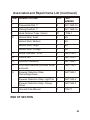
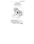
1
TECHNICAL MANUAL
OPERATOR’S MANUAL FOR
ADVANCED COMBAT HELMET (ACH)
ã 2006 Gentex Corporation
WARNING SUMMARY
This warning summary contains general safety warnings and
hazardous materials warnings that must be understood and
applied during operation and maintenance of this equipment.
Failure to observe these precautions could result in serious
injury or death to personnel.
WARNING
All seven (7) helmet pads must be worn at all times. Failure
to observe this precaution could result in serious injury or
death because all seven (7) pads provide maximum impact
protection.
WARNING
The hardware (nut) inside the helmet—where the chinstrap
retention system webbing attaches to the helmet shell in four
places—must be covered by padding during airborne and
other high risk operations such as air assault and
rappelling/mountaineering. The pads must be placed flush
with the rim (edge) of the helmet and completely cover the
hardware—See illustration Pad Placement over Hardware
(Front) and Pad Placement over Hardware (Rear). Failure to
observe this precaution could result in serious injury or death
to personnel because a hard point could contact the wearer’s
head.
WARNING
If you experience fit problems, tightness/looseness, or
helmet profile is too high or too low, refer to Sizing and
Fitting Troubleshooting guidelines.
a
WARNING
When donning the helmet for the first time in a cold
environment, it is necessary to wear the helmet for a few
minutes or otherwise warm the pads, such as by placing in
pockets, so that the pads will conform to the shape of your
head. As the pads warm up and conform to the shape of
your head, it may be necessary to re-tighten the chinstrap
retention system.
WARNING
If you pull too tightly on any strap —or if you don’t position
helmet on head and hold in place with one hand on top of
helmet for initial adjustment— the helmet may become
uncomfortable and tilted on your head and chin cup may
become un-centered.
WARNING
For first aid treatments, refer to FM 21-11.
b
TABLE OF CONTENTS
Page
WARNING SUMMARY . . . . . . . . . . . . . . . . . . . . . . a
HOW TO USE THIS MANUAL . . . . . . . . . . . . . . . . . . iii
GENERAL INFORMATION . . . . . . . . . . . . . . . . . . . iv
CHAPTER 1 - DESCRIPTION AND THEORY OF
OPERATION
Equipment Description and Data . . . . . . . . . . . . . . . . . 1
Theory of Operation . . . . . . . . . . . . . . . . . . . . . . . 10
CHAPTER 2 - OPERATOR INSTRUCTIONS
Sizing and Fitting Instructions . . . . .
Pad Configurations . . . . . . . . . .
Pad Suspension Adjustment . . . . .
Sizing and Fitting Troubleshooting . .
Donning and Doffing . . . . . . . . .
Replacing Retention System . . . . .
Attaching Helmet Cover . . . . . . . .
Installing Front Bracket Assembly Kit .
Installing Eyewear Retention Strap . .
Configuration for Airborne Operations
.
.
.
.
.
.
.
.
.
.
.
.
.
.
.
.
.
.
.
.
.
.
.
.
.
.
.
.
.
.
.
.
.
.
.
.
.
.
.
.
.
.
.
.
.
.
.
.
.
.
.
.
.
.
.
.
.
.
.
.
.
.
.
.
.
.
.
.
.
.
.
.
.
.
.
.
.
.
.
.
.
.
.
.
.
.
.
.
.
.
.
.
.
.
.
.
.
.
.
.
.
.
.
.
.
.
.
.
.
.
.
.
.
.
.
.
.
.
.
.
.
.
.
.
.
.
.
.
.
.
11
15
17
20
26
30
32
35
39
42
.
.
.
.
.
.
.
.
.
.
.
.
.
.
.
.
.
.
.
.
45
47
48
49
CHAPTER 3 - MAINTENANCE PROCEDURES
Replacing the Hardware . . . . . . . . . . . .
Replacing the Pad Suspension . . . . . . . . .
Cleaning Instructions . . . . . . . . . . . . . .
Preventive Maintenance Checks and Services .
.
.
.
.
.
.
.
.
.
.
.
.
i
TABLE OF CONTENTS (Continued)
CHAPTER 4 - SUPPORTING INFORMATION
References . . . . . . . . . . . . .
Components of End Item and
Basic Issue Items Lists . . . . .
Expendable and Durable Items List .
Tool Identification List . . . . . . . .
Associated and Repair Items List . .
ii
. . . . . . . . . . . . . . 53
.
.
.
.
.
.
.
.
.
.
.
.
.
.
.
.
.
.
.
.
.
.
.
.
.
.
.
.
.
.
.
.
.
.
.
.
.
.
.
.
.
.
.
.
.
.
.
.
.
.
.
.
.
.
.
.
54
57
59
61
HOW TO USE THIS MANUAL
OVERVIEW
This manual contains operating instructions and maintenance
procedures for the Advanced Combat Helmet (ACH).
This manual is divided into the following major sections:
Front Cover. Provides information about the equipment covered
by the TM.
Warning Summary. Provides a summary of all warnings that
apply throughout the manual.
Table of Contents. Lists chapters and page numbers in order of
appearance.
Chapter 1, Description and Theory of Operation. Provides
descriptions, equipment data, and theory of operation information.
Chapter 2, Operator Instructions. Provides sizing information,
donning information, and operating instructions in both usual and
unusual conditions.
Chapter 3, Maintenance Procedures. Provides cleaning and
repair instructions and maintenance procedures.
Chapter 4, Supporting Information. Provides reference
information, Components of End Item (COEI)/Basic Issue Items
(BII) Lists, Associated and Repair Items List, and Expendable and
Durable Items List.
iii
ADVANCED COMBAT HELMET
GENERAL INFORMATION
SCOPE
This manual covers the basic fitting and use instructions for the
Advanced Combat Helmet (ACH), hereafter referred to as the
ACH or the helmet.
LIST OF ABBREVIATIONS/ACRONYMS
Components of End Item (COEI)
Basic Issue Items (BII)
Advanced Combat Helmet (ACH)
END OF SECTION
iv
CHAPTER 1
DESCRIPTION AND THEORY OF OPERATION
FOR
ADVANCED COMBAT HELMET (ACH)
ADVANCED COMBAT HELMET
EQUIPMENT DESCRIPTION AND DATA
EQUIPMENT CHARACTERISTICS, CAPABILITIES, AND
FEATURES
The ACH is a helmet system that provides ballistic and impact
protection. This system is compatible with the current night vision
goggles (NVGs), communications packages, and nuclear,
biological, and chemical (NBC) defense equipment and body
armor.
The ACH provides ballistic protection within the full spectrum of
operational environments.
The ACH allows maximum sensory and situational awareness for
the operator. This includes an unobstructed field of view and
increased ambient hearing capabilities.
The ACH’s chinstrap retention system and pad suspension
system provides unsurpassed balance, stability, and comfort. This
system provides for proper size, fit, and ventilation.
The ACH’s pad suspension system provides impact protection
throughout all operational scenarios, including static-line airborne
operations.
1
DESCRIPTION OF MAJOR COMPONENTS
The Advanced Combat Helmet is made up of the following major
components, which are illustrated below:
• helmet shell
• pad suspension system
• retention system with hardware
• helmet cover
• eyewear retention strap (not shown)
PAD
SUSPENSION
SYSTEM
HELMET
COVER
HELMET
SHELL
RETENTION
SYSTEM WITH
HARDWARE
Major Components
2
HELMET
SHELL
HOOK DISKS
Helmet Shell
3
CROWN PAD
(1 IN HELMET)
OBLONG/OVAL PAD
(4 IN HELMET)
TRAPEZOIDAL PAD
(2 IN HELMET)
Pad Suspension System
4
ELASTIC
BAND
ELASTIC
BAND
HARDWARE
CHINCUP
NAPE PAD
BUCKLE
Retention System
5
RETENTION
SYSTEM
(INSIDE
HELMET)
HOLE IN
HELMET SHELL
CONICAL
NUT
(INSIDE
HELMET)
BALLISTIC
SCREW
(OUTSIDE
HELMET)
Hardware
6
COVER
RETAINING
TAB
COMMUNICATIONS
FLAP
Helmet Cover
7
SNAP (SOCKET)
SNAP (STUD)
HOLE FOR MOUNTING
TO HELMET SHELL
Eyewear Retention Strap
8
The following are used in certain operations:
• chemical protective cover
• helmet band
END OF SECTION
9
ADVANCED COMBAT HELMET
THEORY OF OPERATION
This section discusses theory of operation and protective qualities
of the ACH.
This ACH is designed to provide the soldier with ballistic and
impact protection. It is compatible with night vision,
communications, and Nuclear, Biological and Chemical (NBC)
equipment. The small ACH (without the cover) weighs under 3
pounds, the medium weighs 3 pounds, the large weighs 3.3
pounds, and the X-Large weighs 3.8 pounds.
The edge cut of the shell has been reduced when compared to
the Helmet, Ground Troops and Parachutists. This enables better
situational awareness through improved field of vision and
hearing.
The shell provides ballistic protection. The pads act as a
suspension system providing sizing and fitting. In conjunction with
the shell, the pad suspension system provides impact protection.
In conjunction with the chinstrap retention system, the pad
suspension system provides stability.
The chinstrap retention system is a four-point design, attaching to
the shell at four locations. In conjunction with the pad suspension
system, the retention system with the H-shaped nape pad
provides improved stability.
END OF SECTION
10
CHAPTER 2
OPERATOR INSTRUCTIONS
FOR
ADVANCED COMBAT HELMET (ACH)
OPERATION UNDER USUAL CONDITIONS
SIZING AND FITTING INSTRUCTIONS
This section provides instructions for choosing the proper size
ACH.
ACH Shell Sizing
Head Measuring Procedure
Use tape measure and caliper to make the following
measurements.
See Chapter 4, Expendable and Durable Items List, for
appropriate NSNs.
Step 1. Subject must be seated in upright position.
Step 2. Measure head length. Measurement is best made with a
caliper and a ruler. If caliper is not available, an approximate
measurement can be made using a tape measure aligned with the
front and back of head as shown. Record the size measured.
Arrows denote
the proper
alignment of the
caliper or tape
measure.
Measuring Head Length
11
Step 3. Measure head width. Measurement is best made with a
caliper and a ruler. If no caliper is available, an approximate
measurement can be made using a tape measure aligned with
each side of head as shown. Record the size measured.
Step 4. Measure head circumference. Record the size measured.
Arrows denote the
proper alignment of the
caliper or tape measure.
Measuring Head Width
TAPE
MEASURE
Subject sits erect with
head level. Measure
circumference by
passing tape measure
just above the bony
eyebrow ridges of the
forehead and above both
ears. The tape measure
must be pulled tight.
Measuring Head Circumference
12
Step 5. Using the chart below, select the helmet size based on the
largest of the 3 measurements. If a measurement falls on the
dividing line between the two sizes, select the larger size. This is
the proper shell size for the soldier measured.
NOTE
If any measurement falls on the dividing line between sizes, select
the larger size.
Head/Shell Sizing Chart
HELMET
SIZE
PAD
SET
Head Circ.
Head Length
Head Width
English Metric English Metric English Metric
inches mm inches mm inches mm
X-Large
3/4 inch
25.0
636.0
8.6
219.0
6.9
174.0
1 inch
24.3
616.0
8.4
214.0
6.5
164.0
Large
3/4 inch
23.3
591.0
8.1
206.0
6.3
159.0
Medium
3/4 inch
22.5
571.0
7.8
197.0
6.1
154.0
Small
3/4 inch
21.7
551.0
7.4
189.0
5.9
149.0
1 inch
20.5
521.0
7.1
180.0
5.5
139.0
13
ACH Pad Sizing
To select pad size:
1. Assemble helmet in standard pad configuration (see Pad
Configuration in Chapter 2). If other equipment is to be used
with the helmet, such as headset/microphone, evaluate
size with that equipment (if possible).
2. Try on helmet and evaluate fit. Proper fit is achieved when the
helmet does not sit too high (crown pad does not contact head
or too much of forehead is exposed) or too low (too low on
brow or not compatible with eyewear, etc.) and is not too tight
or too loose (see Sizing and Fitting Troubleshooting in
Chapter 2). Shake head rapidly from side to side to check for
stability. Helmet should not rotate from side to side when head
is shaken. While evaluating fit, be sure to have the chinstrap
retention system cinched down.
END OF SECTION
14
OPERATION UNDER USUAL CONDITIONS
PAD CONFIGURATIONS
This section provides instructions for different pad configurations.
Standard Pad Configuration
WARNING
All seven (7) helmet pads must be worn at all times. Failure
to observe this precaution could result in serious injury or
death because all seven (7) pads provide maximum impact
protection.
Below is the standard pad configuration, with the pads placed
vertically. The pads may also be placed in other directions as
described on the next page. See Configuration for Airborne
Operations in Chapter 2 for additional information on pad
placement.)
TRAPEZOIDAL PAD
OBLONG/OVAL
PAD
OBLONG/OVAL
PAD
CROWN
PAD
OBLONG/OVAL
PAD
OBLONG/OVAL
PAD
TRAPEZOIDAL PAD
Standard Pad Configuration
15
Pads can be placed in vertical or horizontal directions (as shown
below) or a combination or at an angle between horizontal and
vertical (diagonal).
It is best to cover hardware with pads in all situations. However,
hardware MUST be covered with pads in high-risk situations.
PADS PLACED
VERTICALLY
PADS PLACED
HORIZONTALLY
Vertical and Horizontal Pad Placement
16
OPERATION UNDER USUAL CONDITIONS
PAD SUSPENSION ADJUSTMENT
This section provides information about the adjusting the pad
suspension system. This unique suspension system is fully
adjustable. The system has the following requirements and
restrictions:
WARNING
The hardware (nut) inside the helmet—where the retention
system webbing attaches to the helmet shell (in four
places)—must be covered by padding during airborne and
other high-risk operations such as air assault and
rappelling/mountaineering. The oblong/oval pad must be
placed flush with the rim (edge) of the helmet and completely
cover the hardware—See illustration Pad Placement over
Hardware (Front) and Pad Placement over Hardware (Rear).
Failure to observe this precaution could result in serious
injury or death to personnel because a hard point could
contact the wearer’s head.
OBLONG/OVAL
PAD
HARDWARE
(NUT)
UNDER PAD
Pad Placement Over Front Hardware (Two Places)
17
OBLONG/OVAL
PAD
HARDWARE
(NUT)
Pad Placement Over Rear Hardware (Two Places)
WARNING
All seven (7) helmet pads must be worn at all times. Failure to
observe this precaution could result in serious injury or death
because all seven (7) pads provide maximum impact protection.
WARNING
If you experience fit problems, tightness/looseness, or helmet
profile is too high or too low, refer to Sizing and Fitting
Troubleshooting guidelines.
NOTE
When donning the helmet for the first time in a cold environment,
it is necessary to wear the helmet for a few minutes or otherwise
warm the pads, such as by placing in pockets, so that the pads
will conform to the shape of your head. As the pads warm up and
conform to the shape of your head, it may be necessary to
re-tighten the chinstrap retention system.
18
NOTE
If you experience hot spots or discomfort, try rearranging the
pad system to accommodate a more comfortable fit. If
discomfort persists, try resizing your shell. (See Sizing and
Fitting Instructions or Sizing and Fitting Troubleshooting,
Chapter 2.)
The direction of the side oblong/oval pads may be changed to
maximize comfort. These pads may be routed vertically from bolt
to crown. This configuration maximizes airflow for better
temperature regulation. These pads may be routed horizontally to
make a seal around the user’s head. This configuration is better
suited for cold weather environments. (See Pad Configurations in
Chapter 2.)
END OF SECTION
19
OPERATION UNDER USUAL CONDITIONS
SIZING AND FITTING TROUBLESHOOTING
This section provides sizing and fitting troubleshooting
techniques.
1. If helmet is too tight:
• Try arranging side pads in a horizontal configuration or
diagonal direction (see pad configuration illustrations in
Chapter 2).
• If rearranging the pads does not alleviate the tightness, try the
next smaller pad size.
Helmet Too Tight
20
2. If too loose (Shake head from side to side while eyes are
closed. If helmet slides on head, it is too loose.)
• Try a larger (thicker) pad set.
• Select the next smaller shell size.
Helmet Too Loose
21
3. If too high: (i.e., too much forehead exposed, crown and does
not touch top of head, or wearer does not see edge of rim):
• Try smaller (thinner) sized pad set.
• Try rearranging pads (horizontal or diagonal—see pad
configuration illustrations in Chapter 2.)
• Try a larger shell size.
It is extremely important that the helmet not be sized and fitted to
sit too high on the head. Here are some things to look for:
If too much of forehead is exposed (approximately more than
½-inch above eyebrow), then the helmet is too high.
TOO MUCH
FOREHEAD EXPOSED
Helmet Too High (Too Much Forehead Exposed)
22
If crown pad does not hit head (wearer cannot feel pad), then
helmet may be too high.
SPACE BETWEEN PAD
AND HEAD
Helmet Too High (Crown Pad Not Touching Head)
23
When fitting, have subject look upward by moving eyes, but
without moving head. If subject cannot see rim of helmet, helmet
may be too high.
WEARER
CANNOT
SEE RIM
Helmet Too High (Looking Past Rim)
24
4. If too low: (i.e. helmet too low on brow, helmet not compatible
with eyewear, or has other similar compatibility issues)
• Try larger (thicker) pad set.
• Try rearranging pads (horizontal or diagonal—see pad
configuration illustrations in Chapter 2.)
Try a smaller helmet shell.
RIM INTERFERES
WITH VISION
AND EYEWEAR
Helmet too low
END OF SECTION
25
OPERATION UNDER USUAL CONDITIONS
DONNING AND DOFFING
This section provides instructions for donning and doffing the
helmet, including adjusting the chinstrap to optimize fit and
comfort.
Donning: To don (put on) the helmet:
Step 1. Check number and placement of pads— (see pad
illustrations in Chapter 2).
Step 2. Prior to donning helmet, loosen all adjustment straps
(ends of chin cup, 2 ladder-locks in front, 2 ladder-locks in back,
and the nape pad). Unbuckle chinstrap buckle.
LADDER
LOCK
LADDER
LOCK
LADDER
LOCK
ENDS OF
CHIN CUP
LADDER
LOCK
NAPE PAD
BUCKLE
Helmet Adjustment Points
26
Step 3. Position helmet on head and buckle chinstrap. Hold
helmet in place with one hand on top of helmet for initial
adjustment.
Positioning Helmet on Head
WARNING
If you pull too tightly on any strap during Steps 4 and 5—or if
you don’t position helmet on head and hold in place with one
hand on top of helmet for initial adjustment as instructed in
Step 3—the helmet may become uncomfortable and tilted on
your head and chin cup may become un-centered.
Step 4. Partially tighten 2 back adjustment straps (one side at a
time).
Tightening Back Adjustment Straps
27
Step 5. Partially tighten 2 front straps (one side at a time) by
moving the slides up.
Tightening Front Straps
Step 6. With both hands, fully tighten front and back adjustment
straps.
Tightening Front and Back Straps
28
Step 7. The nape pad can be can be slid up and down along the
rear legs of the chinstrap. It can be positioned according to
personal comfort. When tightened (see figure below) against the
nape by pulling on end of webbing, the nape pad adds additional
stability to the helmet such as when wearing NVGs. Keep the
nape pad away from the ladder-locks while adjusting the chinstrap
to prevent jamming.
Releasing Buckle
Doffing: To doff (remove) the helmet:
To doff the helmet, press the sides of the center section of the
buckle on the chinstrap retention system inward. Once the buckle
releases, remove the helmet.
END OF SECTION
29
OPERATION UNDER USUAL CONDITIONS
REPLACING RETENTION SYSTEM
This section provides instructions for replacing the ACH’s
retention system.
1. Unthread the chinstrap retention system webbing from the
ladder-lock.
2. Lay the helmet on its crown with the front of the helmet away
from you (buckle is located on right side of helmet.) Drape the
replacement retention system over the helmet with the
nape-strap pad facing down on the back/rear of the helmet (see
Chinstrap Retention Orientation illustration below).
3. Insert and thread the four legs of the retention system into their
corresponding ladder locks. (See Routing of Retention System
Webbing through Ladder Lock illustration on the next page.)
For illustration of entire assembled helmet with retention and
hardware—please refer to Chapter 1. Take care to ensure that
webbing is not twisted.
4. Slide elastic band over loose ends of webbing.
BUCKLE
Retention System Orientation
30
Routing of Retention System Webbing Through Ladder Lock
END OF SECTION
31
OPERATION UNDER USUAL CONDITIONS
ATTACHING HELMET COVER
This section provides instructions for attaching the camouflage
helmet cover to your ACH.
There are two covers available for the ACH: a reversible
woodland/desert cover and a white (Artic) cover.
FRONT OF HELMET
Helmet Cover
(Outside, Back)
Helmet
Cover
(Inside)
BUTTONHOLES
HOOK AND LOOP
RETAINING TABS
COMMUNICATIONS
FLAP
Helmet Cover
1. Remove the suspension pads from the inside of the helmet
shell.
2. Remove the chinstrap retention system webbing (see
Chapter 2).
3. Select the camouflage pattern to be worn and orient the cover
so that the desired pattern is on the outside if using the
reversible cover.
4. Align the label (found on rear of helmet cover) with the rear of
the helmet shell.
32
5. Pull the cover over the back and sides of helmet shell.
6. Thread each ladder-lock through the corresponding buttonhole
in the cover.
7. Pull the cover retaining tabs down and attach tabs to hook
disks inside helmet shell. Ensure tight smooth fit of cover by
pulling the retaining tabs until tight.
8. Place suspension pads back into shell. (See Page 15.)
9. Replace retention system webbing. (See Page 30 for
instructions for replacing the retention.)
RETENTION STRAP
THREADED
THROUGH COVER
(4 PLACES)
COVER
RETAINING
TABS
HOOK DISK
Helmet Cover Installed
33
The communications flap is used to store cables from the headset
microphone that is sometimes used with the helmet.
The flap can also be used to secure goggle straps if no eyewear
retention straps are available. Lift the flap and place the goggle
strap under the flap. Re-secure the flap by pressing the hook and
loop together.
END OF SECTION
34
OPERATION UNDER USUAL CONDITIONS
INSTALLING FRONT BRACKET ASSEMBLY KIT
This section provides instructions for installing the front bracket
assembly kit on the ACH.
1. Make sure that the front bracket assembly kit has all the
components. You should have a front bracket assembly, a
screw, and a threaded post (see illustration below). See
Chapter 4, Associated and Repair Items List, for the
appropriate part number.
2. Install the helmet cover on your helmet. See Page 32 for
instructions on attaching the helmet cover.
FRONT BRACKET
ASSEMBLY
THREADED POST
SCREW
Front Bracket Assembly Kit Contents
35
3. Place the front bracket assembly on the helmet over the helmet
cover. Line up the hole in the plate, the front buttonhole in the
cover, and the hole in the helmet shell (see “Front Bracket
Assembly Positioned Helmet” illustration in this section). Move
the cover around to line up the buttonhole in the cover.
4. Insert the screw through the front bracket assembly, cover, and
into shell from the outside of the helmet. Insert the threaded
post from inside the helmet. Start to tighten the screw and post
(see “Front Bracket Assembly Positioned Helmet” illustration in
this section).
5. Before completely tightening the screw, ensure that the cleat of
front bracket assembly is tight against the rim of the helmet
(see “Front Bracket Assembly Positioned Helmet” illustration in
this section). Push the bracket up so that the cleat is tight
against the rim (edge) of the helmet while tightening the screw
and post. It may be helpful to have another person assist with
this step.
CAUTION
Do not over tighten the screw, or the front bracket assembly
may break.
36
Helmet Cover
Screw located on the
outside of the helmet
and inserted through
front bracket assembly
and helmet cover into
hole in the shell.
Post located on
the inside of
helmet and
inserted into hole
in the shell.
Front Bracket Assembly Positioned on Helmet
37
NOTE
If no NVG Front Bracket is used—and the helmet has a hole
for the front bracket—plug the hole with the 8-32 x 3/8 long
screw and post. See Chapter 4, Associated and Repair
Items List, for the appropriate part number.
END OF SECTION
38
OPERATION UNDER USUAL CONDITIONS
INSTALLING EYEWEAR RETENTION STRAP
This section provides instructions for installing the eyewear
retention strap on the ACH.
1. Make sure you have two eyewear retention straps (see Chapter
4, Associated and Repair Items List, for the appropriate part
number).
2. If the helmet cover is installed, remove the rear cover retaining
tabs and slide the rear half of the cover up to expose the two
rear screws. You can also remove the cover completely (see
Page 32).
3. Remove one of the two rear screws. Place an eyewear
retention strap over the barrel (shaft) of the screw with the snap
socket and stud facing away from the helmet. (See Eyewear
Retention Strap and Screw Assembly illustration in this
section.) A strap is installed on each of the two rear screws.
4. Insert the screw with eyewear retention strap attached into hole
in helmet.
5. Place the retention system strap and nut (inside the helmet)
on the screw and tighten to a torque of 80-100 inch-ounces, or
until the nut bottoms out on the screw. (See Chapter 3, Page
45, which shows screw and nut installation, for replacing the
hardware.)
6. Repeat Steps 3-5 to install the other eyewear retention strap on
the other rear screw.
7. Install the helmet cover. While installing the cover, thread
eyewear retention strap through lower most rear buttonhole on
cover (see Page 33 for attaching the helmet cover). (See
Helmet with Eyewear Retention Strap Installed illustration for
finished assembly.)
39
SNAP
(STUD)
SNAP (SOCKET)
NUT
SCREW
HOLE IN EYEWEAR
RETENTION STRAP
RETENTION SYSTEM
HOLE IN HELMET SHELL
Eyewear Retention Strap and Screw Assembly
40
EYEWEAR RETENTION STRAP
HELMET COVER
SCREW (SHOWN
UNDER COVER)
LOWEST REAR
BUTTONHOLE
Helmet With Eyewear Retention Strap Installed
41
OPERATION UNDER USUAL CONDITIONS
CONFIGURATION FOR AIRBORNE OPERATIONS
This section provides instructions for configuring the ACH for
airborne operations as well as other high-risk operations such as
air assault and rappelling/mountaineering. No other parts or
components are required for airborne use of the helmet.
WARNING
The hardware (nut) inside the helmet—where the chinstrap
retention system webbing attaches to the helmet shell in four
places—must be covered by padding during airborne and other
high risk operations such as air assault and rappelling/
mountaineering. The oblong/oval pad must be placed flush with
the rim (edge) of the helmet and completely cover the
hardware—See illustration Pad Placement over Hardware (Front)
and Pad Placement over Hardware (Rear). Failure to observe this
precaution could result in serious injury or death to personnel
because a hard point could contact the wearer’s head.
WARNING
All seven (7) helmet pads must be worn during airborne
operations and should be worn during other high risk operations
such as air assault and rappelling/mountaineering. Failure to
observe this precaution could result in serious injury or death
because all seven (7) pads provide maximum impact protection.
WARNING
The rear pads must be placed flush with the rim (edge) of the
helmet for airborne operations. If you experience helmet rotation
during airborne operations the rear pads can be placed so that
they extend ½” beyond the rim of the helmet. Placement of the
rear pads flush or beyond the rim (edge) of the helmet prevents
the hard shell from hitting your neck. (See Pad Placement over
Hardware (Front) and Pad Placement over Hardware (Rear)
illustrations.)
END OF SECTION
42
PAD
HARDWARE
Pad Placement Over Front Hardware Hardware (Two Places)
PAD
HARDWARE
Pad Placement Over Hardware (Two Places)
43
CHAPTER 3
MAINTENANCE PROCEDURES
FOR
ADVANCED COMBAT HELMET
MAINTENANCE PROCEDURES
REPLACING THE HARDWARE
This section provides instructions for replacing the ACH’s
hardware (screw or nut).
NOTE
To replace hardware, use a standard flathead screwdriver. If
this tool is unavailable, a coin may be used.
You may need to use a second screwdriver to hold the nut in
place while you remove the screw. (See Hardware
Installation illustration in this section.)
1. Remove the retention system as described in Chapter 2.
2. Remove the screw with a standard flathead screwdriver.
3. Replace screw and nut. Ensure the proper orientation hardware
and retention system. (See Hardware Installation illustration in
this section.) Tighten the screw to a torque of 80-100
inch-ounces, or until the nut bottoms out on the screw.
4. Inspect the screws to ensure tightness. If loosening persists,
use the sealing compound (thread-locking compound; see
Page 57, Expendable and Durable Items List). Follow directions
on container.
45
SECOND
SCREWDRIVER
RETENTION
SYSTEM
STRAP
CONICAL
NUT
BALLISTIC
SCREW
Hardware Installation
END OF SECTION
46
MAINTENANCE PROCEDURES
REPLACING THE PAD SUSPENSION
This section provides information on replacing the pad
suspension.
Replacing Pad Suspension
NOTE
On one side the pads are covered with a loop material. On the
other side, the pads are covered by moisture-wicking fabric.
ONLY THE LOOP SIDE OF THE PAD WILL ATTACH TO THE
HOOK DISKS ON THE HELMET SHELL. Press the pad against
the hook disks. The loop side of the pad is green.
1. Pull the individual pads off the inner helmet hook disks.
2. Reattach suspension pads as needed. (See Chapter 2 for Pad
Configurations and Pad Suspension Adjustment.)
END OF SECTION
47
MAINTENANCE PROCEDURES
CLEANING INSTRUCTIONS
This section provides instructions for cleaning the ACH.
Helmet Shell
1. Clean with mild soap and water. Use a soft brush or cloth.
2. Allow to air dry.
A small brush is useful in removing dirt from the hook disks on the
inside of the shell.
Chinstrap, Helmet Cover, and Pad Suspension
1. Clean with mild soap and water. Wash by hand or in machine in
the gentle cycle, cold water.
2. Allow to air dry. DO NOT MACHINE DRY.
Keeping the hook and loop clean will help to maintain its ability to
stick together.
END OF SECTION
48
MAINTENANCE PROCEDURES
PREVENTIVE MAINTENANCE CHECKS AND SERVICES
INTRODUCTION
General
Preventive maintenance checks and services (PMCS) are
performed to keep the ACH in operating condition. The checks
are used to find, correct, and report problems. The operator is to
do the PMCS tasks shown in PMCS Table 1. PMCS is to be done
before, during, and after use of the ACH.
Before you use the ACH, perform PMCS.
During use of the ACH, periodically perform PMCS.
After you have used the ACH, perform PMCS.
PMCS Column Description
ITEM – The order the PMCS should be performed and a
reference number for maintenance forms. INTERVAL – Tells
when the check should be performed. ITEM TO BE CHECKED
OR SERVICED – Tells which items to perform the PMCS
procedure on. PROCEDURE – Tells the procedure to perform. If
item cannot be repaired, it must be replaced. EQUIPMENT NOT
READY IF – Tells what conditions render the ACH unfit to perform
the mission.
49
Table 1. Preventive Maintenance Checks and Services
ITEM
NO.
INTERVAL
ITEM TO BE
PROCEDURE
CHECKED OR
SERVICED
EQUIPMENT NOT
READY/
AVAILABLE IF
1
Before
Chinstrap
Retention
System
Chinstrap webbing
has cuts, frays, or
other damage.
50
Check for:
1) Cuts, frays or
other damage or
loose or damaged
stitching in the
webbing. If
webbing is frayed
more than ½” or
has a discernable
cut, or loose or
damaged
stitching, refer to
higher level
maintenance for
repair.
2) Cracked, worn,
or damaged
hardware
(p-clamp,
ladderlock, nut,
screw) and
buckle. Refer to
higher level
maintenance for
repair.
3) Loose screws.
Tighten screws or
refer to higher
level
maintenance if
loose.
Hardware or buckle
is cracked, worn, or
damaged.
Screws are loose.
Table 1. Preventive Maintenance Checks and Services
ITEM
NO.
INTERVAL
ITEM TO BE
PROCEDURE
CHECKED OR
SERVICED
EQUIPMENT NOT
READY/
AVAILABLE IF
2
Before
Pads
Cuts, tears or
other damage to
outer fabric or
inner foam. If
pads are torn or
cut, exposing the
inner padding,
replace.
Pads are torn, cut
or otherwise
damaged.
3
Before
Shell
1) Gouges,
scrapes, cracks,
delamination or
other damage to
shell. If gouges,
scrapes, or
damage extends
below the surface
(below the paint),
refer to higher
level
maintenance for
repair.
Gouges, scrapes,
cracks,
delamination or
other damage
extends below the
surface (below the
paint).
2) Loose or
damaged edge
beading. Refer to
higher level
maintenance for
repair.
Edging is
excessively loose or
damaged.
3) Loose or
damaged hook
disks. Refer to
higher level
maintenance for
repair.
Hook disks are
damaged such that
they will not
securely hold the
pads in place.
51
Table 1. Preventive Maintenance Checks and Services
ITEM
NO.
INTERVAL
ITEM TO BE
PROCEDURE
CHECKED OR
SERVICED
EQUIPMENT NOT
READY/
AVAILABLE IF
4
Before
Cover
Cuts, frays or
other damage to
the fabric or cut
or frayed
stitching. Refer to
higher level
maintenance for
repair.
Excessive cuts,
frays, or other
damage to the
fabric or cut or
frayed stitching.
5
During
Chinstrap
Retention
System
Inspect for
damaged
components (see
Item 1)
Chinstrap
components are
damaged. See
above.
6
After
Chinstrap
Retention
System, Pads,
Hardware,
Shell.
Perform all PMCS
steps in Items
1-4after use.
END OF SECTION
52
CHAPTER 4
SUPPORTING INFORMATION
FOR
ADVANCED COMBAT HELMET (ACH)
SUPPORTING INFORMATION
REFERENCES
This section lists related field manuals, forms, technical manuals,
and miscellaneous publications.
FIELD MANUALS
FM 3-5
Tactics of Chemical Warfare
FM 21-11
First Aid for Soldiers
FM 3-21.220
Static Line Parachuting Techniques and
Training
FORMS
DA Form 2028
Recommended changes to Publications
and Blank Forms
SF 368
Product Quality Deficiency Report
TECHNICAL MANUALS
TM 10-8400-203-23
Unit and Direct Support Maintenance
Manual for General Repair Procedures
for Individual Equipment
TM 11-5855-262-10-2
Night Vision Goggles AN/PVS-7B
(NSN 5855-01-228-0937) (EIC: LPS)
and AN/PVS-7D (NSN 5855-01-422- 54)
(EIC: N/A) (TO 12S10-2PVS7-11;
TM 09500A-10/1A; NAVSEA SW215-AT
TM 11-5855-306-10
Monocular Night Vision Device
AN/PVS-14 (NSN 5855-01-432-0524)
(EIC: N/A) (TM 10271A-10/1)
MISCELLANEOUS PUBS
DA PAM 738-750
Functional User’s Manual for the Army
Maintenance
END OF SECTION
53
SUPPORTING INFORMATION
COMPONENTS OF END ITEM AND BASIC ISSUE ITEMS LISTS
INTRODUCTION
Scope
This section lists COEI and BII for the Advanced Combat Helmet
to help you inventory items for safe and efficient operation of the
equipment.
General
The COEI and BII information is divided into the following lists:
Components of End Item (COEI). This list is for information
purposes only and is not authority to requisition replacements.
These items are part of the helmet. As part of the end item, these
items must be with the end item whenever it is issued or
transferred between property accounts. Items of COEI are
removed and separately packaged for transportation or shipment
only when necessary. Illustrations are furnished to help you find
and identify the items.
Basic Issue Items (BII). These essential items are required to
place the Advanced Combat Helmet in operation, operate it, and
to do emergency repairs. Although shipped separately packaged,
BII must be with the Advanced Combat Helmet during operation
and when it is transferred between property accounts. Listing
these items is your authority to request/requisition them for
replacement based on authorization of the end item by the
TOE/MTOE. Illustrations are furnished to help you find and
identify the items.
Explanation of Columns in the COEI List and BII List
Column (1) Illus Number. Gives you the number of the item
illustrated.
Column (2) National Stock Number (NSN). Identifies the stock
number of the item to be used for requisitioning purposes.
54
Column (3) Description, CAGEC, and Part Number. Identifies
the Federal item name (in all capital letters) followed by a
minimum description when needed. The stowage location of COEI
and BII is also included in this column. The last line below the
description is the CAGEC (Commercial and Government Entity
Code) (in parentheses) and the part number.
Column (4) Usable On Code. When applicable, gives you a code
if the item you need is not the same for different models of
equipment. (Add the following only as applicable. Replace Xs with
appropriate codes and model numbers.) Column (5) Unit of
Issue (U/I). Indicates the physical measurement or count of the
item as issued per the National Stock Number shown in column
(2).
Column (6) Qty Rqr. Indicates the quantity required.”
Components of End Item
(1)
Illus
Number
(2)
National Stock
Number
(3)
(4)
Usable
on
Code
(5)
U/I
(6)
QTY
Retention System
97427/05D11948-1
N/A
ea
1
Pad Suspension
System, 3/4"
97427/05C11950-1
N/A
set
1
Pad Suspension
System, 1"
97427/05C11950-2
N/A
set
1
Description, CAGEC,
and Part Number
55
Basic Issue Items (BII) List
(1)
Illus
Number
(2)
National Stock
Number
(4)
Usable
on
Code
(5)
U/I
(6)
QTY
8415-01-515-4662
Cover, Helmet,
Reversible, with
communication flap,
size S/M
97427/04A11921-1
N/A
ea
1
8415-01-515-4663
Cover, Helmet,
Reversible, with
communication flap,
size L/XL
97427/04A11921-2
N/A
ea
1
8415-01-515-4671
Cover, Helmet,
Reversible, without
communication flap,
size S/M
97427/04D11921-3
N/A
ea
1
8415-01-515-4672
Cover, Helmet,
Reversible, without
communication flap,
size L/XL
97427/04D11921-4
N/A
ea
1
8415-01-521-8806
Cover, Helmet,
Camouflage, Universal
Print, Non-Reversible,
S/M, with
communications flap
N/A
ea
1
8415-01-521-8808
Cover, Helmet,
Camouflage, Universal
Print, Non-Reversible,
L/XL, with
communications flap
N/A
ea
1
END OF SECTION
56
(3)
Description, CAGEC,
and Part Number
SUPPORTING INFORMATION
EXPENDABLE AND DURABLE ITEMS LIST
INTRODUCTION
Scope
This section lists expendable and durable items that you will need
to operate and maintain the Advanced Combat Helmet. This list is
for information only and is not authority to requisition the listed
items. These items are authorized to you by CTA 50-970,
Expendable/Durable Items (Except Medical, Class V Repair Parts,
and Heraldic Items), or CTA 8-100, Army Medical Department
Expendable/Durable Items.
Explanation of Columns in the Expendable/Durable
Items List
Column (1) Item Number. This number is assigned to the entry
in the list and is referenced in the narrative instructions to identify
the item.
Column (2) Level. This column identifies the lowest level of
maintenance that requires the listed item (include as applicable:
C = Operator/Crew, O = Unit/AVUM, F = Direct Support/AVIM,
H = General Support, D = Depot).
Column (3) National Stock Number (NSN). This is the NSN
assigned to the item which you can use to requisition it.
Column (4) Item Name, Description, Commercial and
Government Entity Code (CAGEC), and Part Number (P/N).
This column provides the other information you need to identify
the item.
Column (5) Unit of Issue (U/I). Indicates the physical
measurement or count of the item as issued per the National
Stock Number shown in column (3).
57
Table 1. Expendable and Durable Items List
(1)
(2)
ITEM LEVEL
#
(3)
NATIONAL
STOCK
NUMBER
(4)
ITEM NUMBER,
DESCRIPTION,
CAGEC, PART
NUMBER
(5)
U/I
5210-01-434-9493
Caliper
ea
Cloth
ea
Measuring tape
ea
4
Mild Soap
ea
5
Soft Brush
ea
Sealing Compound
bx
1
2
3
6
8315-00-782-3520
8030-01-104-5392
END OF SECTION
58
SUPPORTING INFORMATION
TOOL IDENTIFICATION LIST
INTRODUCTION
Scope
This section lists all common tools and supplements and special
tools/fixtures needed to maintain the ACH.
Explanation of Columns in the Tool Identification List
Column (1) Item Number. This number is assigned to the entry
in the list and is referenced in the initial setup to identify the item.
Column (2) Item Name. This column lists the item by noun
nomenclature and other descriptive features.
Column (3) National Stock Number. This is the National Stock
Number (NSN) assigned to the item; use it to requisition the item.
Column (4) Part Number/CAGEC. Indicates the primary number
used by the manufacturer (individual, company, firm, corporation,
or Government activity) which controls the design and
characteristics of the item by means of its engineering drawings,
specifications, standards, and inspection requirements to identify
an item or range of items. The manufacturer’s Commercial and
Government Entity Code (CAGEC) is also included.
Column (5) Reference. This column identifies the authorizing
supply catalog or RPSTL for items listed in this section.”
59
Tool Identification List
ITEM
NO.
ITEM
NAME
1
Screwdriver
END OF SECTION
60
NATIONAL
STOCK
NUMBER
PART
NUMBER/
CAGEC
REFERENCE
SUPPORTING INFORMATION
ASSOCIATED AND REPAIR ITEMS LIST
1
10
2
13
9
3
11
12
6
15
14
5, 8
4, 7
ACH Repair Items
61
Associated and Repair Items List
ITEM
#
NOMENCLATURE
QTY.
PART
NUMBER
1
Helmet, Advanced Combat, Small
1
05D11955-1
Helmet, Advanced Combat, Medium 1
05D11955-2
Helmet, Advanced Combat, Large
1
05D11955-3
Helmet, Advanced Combat, X-Large 1
05D11955-4
Cover, Helmet, Reversible, with
communication flap, size S/M
1
04A11921-1
Cover, Helmet, Reversible, with
communication flap, size L/XL
1
04A11921-2
Cover, Helmet, Reversible, without
communication flap, size S/M
1
04A11921-3
Cover, Helmet, Reversible, without
communication flap, size M/L
1
04A11921-4
Cover, Helmet, Foliage Green, S/M
1
04A11921-5
Cover, Helmet, Foliage Green, L/XL 1
04A11921-6
Pad Set, 3/4"
1
05C11950-1
Pad Set, 1"
1
05C11950-2
4
Trapezoidal Pad, 3/4"
2
05C11950-13
5
Oblong/Oval Pad, 3/4"
4
05C11950-12
6
Crown Pad, 3/4" Thick
1
05C11950-11
2
3
62
Associated and Repair Items List (Continued)
ITEM
#
NOMENCLATURE
QTY. PART
NUMBER
7
Trapezoidal Pad, 1"
2
05C11950-15
8
Oblong/OvaPad, 1"
4
05C11950-14
9
Hook Fastener Tape, Velcoin
21
71206-1
10
Helmet Shell, Small
1
N/A
Helmet Shell, Medium
1
N/A
Helmet Shell, Large
1
N/A
Helmet Shell, X-Large
1
N/A
11
Screw, Shoulder, 10-32
4
05B12190-1
12
Conical Nut
4
04B11815-1
13
Retention Assembly
1
05D11948-1
14
NVG Mount Bracket (includes screw
and post)
1
03B11760-1
15
Eyewear Retention Strap,
Camouflage Green
1
05A11945-1
Eyewear Retention Strap, Light Tan
1
05A11945-2
Eyewear Retention Strap, Foliage
Green
1
05A11945-3
Use and Care Manual
1
TP0271
END OF SECTION
63
TP0271 REV. 1
FEBRUARY 2006