1
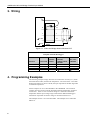
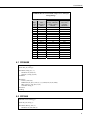
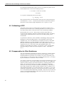
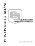
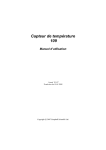
3WHB10K 3-Wire
Half Bridge
Terminal Input Module
User Manual
Issued 19.9.07
Copyright © 1996-2007 Campbell Scientific Inc.
Printed under licence by Campbell Scientific Ltd.
CSL341
Guarantee
This equipment is guaranteed against defects in materials and
workmanship. This guarantee applies for twelve months from date of
delivery. We will repair or replace products which prove to be defective
during the guarantee period provided they are returned to us prepaid. The
guarantee will not apply to:
•
Equipment which has been modified or altered in any way without the
written permission of Campbell Scientific
•
Batteries
•
Any product which has been subjected to misuse, neglect, acts of God
or damage in transit.
Campbell Scientific will return guaranteed equipment by surface carrier
prepaid. Campbell Scientific will not reimburse the claimant for costs
incurred in removing and/or reinstalling equipment. This guarantee and the
Company’s obligation thereunder is in lieu of all other guarantees,
expressed or implied, including those of suitability and fitness for a
particular purpose. Campbell Scientific is not liable for consequential
damage.
Please inform us before returning equipment and obtain a Repair
Reference Number whether the repair is under guarantee or not. Please
state the faults as clearly as possible, and if the product is out of the
guarantee period it should be accompanied by a purchase order.
Quotations for repairs can be given on request.
When returning equipment, the Repair Reference Number must be clearly
marked on the outside of the package.
Note that goods sent air freight are subject to Customs clearance fees
which Campbell Scientific will charge to customers. In many cases, these
charges are greater than the cost of the repair.
Campbell Scientific Ltd,
Campbell Park, 80 Hathern Road,
Shepshed, Loughborough, LE12 9GX, UK
Tel: +44 (0) 1509 601141
Fax: +44 (0) 1509 601091
Email: [email protected]
www.campbellsci.co.uk
Contents
PDF viewers note: These page numbers refer to the printed version of this document. Use
the Adobe Acrobat® bookmarks tab for links to specific sections.
1. Function ....................................................................... 1
2. Specifications .............................................................. 1
3. Wiring ........................................................................... 2
4. Programming Examples ............................................. 2
4.1
4.2
4.3
4.4
4.5
CR9000X ..................................................................................................3
CR1000.....................................................................................................3
CR10(X) ...................................................................................................4
21X ...........................................................................................................4
CR7...........................................................................................................5
5. 100 Ohm PRT in 3-Wire Half Bridge ........................... 5
5.1 Excitation Voltage ....................................................................................5
5.2 Calibrating a PRT .....................................................................................6
5.3 Compensation for Wire Resistance...........................................................6
Figures
1-1. Terminal Input Module ...........................................................................1
2-1. Schematic ................................................................................................1
3-1. 3-Wire Half Bridge Used to Measure PRT .............................................2
Tables
3-1. 3WHB10K Connections to Campbell Scientific Dataloggers.................2
4-1. Excitation Voltage for 100 Ohm PRT in 3WHB10K Based on
Maximum Temperature and Input Voltage Range...............................3
i
This is a blank page.
3WHB10K 3-Wire Half Bridge Terminal
Input Module
1. Function
Terminal input modules connect directly to the datalogger's input terminals to
provide completion resistors for resistive bridge measurements, voltage dividers,
and precision current shunts.
H
L
G
H
L
AG
H
L
AG
Figure 1-1. Terminal Input Module
2. Specifications
10 kOhm Completion Resistor
Tolerance @ 25°C
Temperature coefficient
0°-60°C
-55°-125°C
Power rating @ 70°C
±0.01%
±4 ppm/°C
±8 ppm/°C
0.25 W
Vx
10 kΩ
H
H
L
L
or AG
G
Figure 2-1. Schematic
1
3WHB10K 3-Wire Half Bridge Terminal Input Module
3. Wiring
Datalogger
Vx
10 kΩ
H
H
L
L
or AG
G
or G
A
B
Shield
Figure 3-1. 3-Wire Half Bridge Used to Measure PRT
Table 3-1. 3WHB10K Connections to
Campbell Scientific Dataloggers
Function
Label/Lead
CR10X,
CR510
Excitation
V1 Reference
V2 Sense
Ground
Black Wire
H
L
G
E1
SE1
SE2
AG
CR23X,
CR1000,
CR800, CR850,
CR3000
EX1
SE1
SE2
21X, CR7,
CR9000X
Excitation 1
1H
1L
4. Programming Examples
The following examples simply show the two instructions necessary to 1) make
the measurement and 2) calculate the temperature. The result of the 3-wire half
bridge measurement as shown is Rs/Ro, the input required for the PRT algorithm
to calculate temperature.
All the examples are for a 100 Ohm PRT in the 3WHB10K. The excitation
voltages used were chosen with the assumption that the temperature would not
exceed 50°C. Table 4-1 lists excitation voltage as a function of maximum
temperature and the input voltage ranges used with the different dataloggers.
Calculation of optimum excitation voltage is discussed in Section 5.1.
The multiplier shown is for a 100 Ohm PRT. The multiplier for a 1000 Ohm
PRT is 10.
2
User Manual
Table 4-1. Excitation Voltage for 100 Ohm PRT in
3WHB10K Based on Maximum Temperature and Input
Voltage Range
Max.
Temp
°C
50
100
150
200
250
300
350
400
450
500
550
600
650
700
750
800
850
PRT
Resistance
Ohms
119.4
138.5
157.31
175.84
194.07
212.02
229.67
247.04
264.11
280.9
297.39
313.59
329.51
345.13
360.47
375.51
390.26
Excitation Voltage, mV
±25 mV Input
±50 mV Range,
Range, CR10(X),
21X, CR7,
CR800, CR850,
CR3000,
CR1000,
CR9000X
2119
4237
1830
3660
1614
3228
1447
2893
1313
2626
1204
2408
1113
2227
1037
2074
971
1943
915
1830
866
1731
822
1644
784
1567
749
1499
718
1437
691
1381
666
1331
4.1 CR9000X
'CR9000X Datalogger
Public RS_Ro, Temp_F
DataTable (Temp_F,1,-1)
DataInterval (0,0,0.10)
Sample (1,Temp_F,FP2)
EndTable
BeginProg
Scan (1,mSec,0,0)
BrHalf3W (Rs_Ro,1,V50,5,1,6,1,1,4200,True,30,40,100,0)
PRT (Temp_F,1,Rs_Ro,1.8,32)
CallTable Temp_F
NextScan
EndProg
4.2 CR1000
'CR1000 Series Datalogger
Public Rs_R0, Temp_C
DataTable (Hourly,True,-1)
DataInterval (0,60,Min,0)
3
3WHB10K 3-Wire Half Bridge Terminal Input Module
Average (1,Temp_C,IEEE4,0)
EndTable
BeginProg
Scan (1,Sec,0,0)
BrHalf3W (Rs_R0,1,mV25,1,Vx1,1,2100,True ,0,250,100,0)
PRT (Temp_C,1,Rs_R0,1.0,0)
CallTable Hourly
NextScan
EndProg
4.3 CR10(X)
1: 3W Half Bridge (P7)
1: 1
Reps
2: 23
± 25 mV 60 Hz Rejection Range
3: 1
SE Channel
4: 1
Excite all reps w/Exchan 1
5: 2100
mV Excitation
6: 1
Loc [ Rs_R0 ]
7: 100
Mult
8: 0
Offset
2: Temperature RTD (P16)
1: 1
Reps
2: 1
R/RO Loc [ Rs_R0
3: 2
Loc [ Temp_C ]
4: 1.0
Mult
5: 0.0
Offset
]
4.4 21X
1: 3W Half Bridge (P7)
1: 1
Reps
2: 3
± 50 mV Slow Range
3: 1
SE Channel
4: 1
Excite all reps w/Exchan 1
5: 4200
mV Excitation
6: 1
Loc [ Rs_R0 ]
7: 100
Mult
8: 0
Offset
2: Temperature RTD (P16)
1: 1
Reps
2: 1
R/RO Loc [ Rs_R0
3: 2
Loc [ Temp_C ]
4: 1.0
Mult
5: 0
Offset
4
]
User Manual
4.5 CR7
1: 3-Wire Half Bridge (P7)
1: 1
Reps
2: 4
± 50 mV Slow Range
3: 1
In Card
4: 1
SE Channel
5: 1
Ex Card
6: 1
Ex Channel
7: 1
Meas/Ex
8: 4200
mV Excitation
9: 1
Loc [ Rs_R0 ]
10: 100
Mult
11: 0
Offset
2: Temperature RTD (P16)
1: 1
Reps
2: 1
R/RO Loc [ Rs_R0
3: 2
Loc [ Temp_C ]
4: 1
Mult
5: 0
Offset
]
5. 100 Ohm PRT in 3-Wire Half Bridge
The advantages of the 3-wire half bridge over other measurements that correct
for lead wire resistance such as a 4-wire half bridge, are that it only requires 3
lead wires going to the sensor and takes 2 single-ended input channels, whereas
the 4-wire half bridge requires 4 wires and 2 differential channels.
The result of the 3-wire half bridge instruction is equivalent to the ratio of the
PRT resistance, Rs to the resistance of the 10 k fixed resistor, Rf.
Rs
Rf
The RTD Instruction (16) computes the temperature (°C) for a DIN 43760
standard PRT from the ratio of the PRT resistance at the temperature being
measured (Rs) to its resistance at 0°C (R0). Thus, a multiplier of Rf/R0 is used
with the 3-wire half bridge instruction to obtain the desired intermediate, Rs/R0 =
(Rs/Rf x Rf/Ro). When Rf = 10,000 and R0 = 100, the multiplier is 100; when R0
is 1000 the multiplier is 10.
The fixed resistor must be thermally stable. Over the -55° to 85°C extended
temperature range for the datalogger, the ±4 ppm/°C temperature coefficient
would result in a maximum error of ±0.04°C at 60°C. The
±8 ppm/°C temperature coefficient would result in a maximum error of ±0.13°C
at -55°C.
5.1 Excitation Voltage
The best resolution is obtained when the excitation voltage is large enough to
cause the signal voltage to fill the measurement voltage range. The voltage drop
across the PRT is equal to the current, I, multiplied by the resistance of the PRT,
Rs, and is greatest when Rs is greatest. For example, if it is desired to measure a
temperature in the range of -10 to 40°C, the maximum voltage drop will be at
40°C when Rs = 115.54 Ohms. To find the maximum excitation voltage that can
5
3WHB10K 3-Wire Half Bridge Terminal Input Module
be used when the measurement range is ±25 mV, we assume V2 equal to 25 mV
and use Ohm's Law to solve for the resulting current, I.
I = 25 mV/Rs = 25 mV/115.54 Ohms
= 0.216 mA
Vx is equal to I multiplied by the total resistance:
Vx = I(Rs+Rf) = 2.18 V
If the actual resistances were the nominal values, the 25 mV range would not be
exceeded with Vx = 2.18 V. To allow for the tolerances in the actual resistances
and to leave a little room for higher temperatures, set Vx equal to 2.1 volts.
5.2 Calibrating a PRT
The greatest source of error in a PRT is likely to be that the resistance at 0°C
deviates from the nominal value. Calibrating the PRT in an ice bath can correct
this offset and any offset in the fixed resistor in the Terminal Input Module.
With the PRT at 0°C, Rs = R0. Thus, the above result becomes R0/Rf, the
reciprocal of the multiplier required to calculate temperature, Rf/R0. By making
a measurement with the PRT in an ice bath, errors in both Rs and R0 can be
accounted for.
To perform the calibration, connect the PRT to the datalogger and program the
datalogger to measure the PRT with the 3-wire half bridge as shown in the
example section. For a 100 Ohm PRT use a multiplier of 100; for a 1000 Ohm
PRT use a multiplier of 10. Place the PRT in an ice bath (@ 0°C; Rs = R0).
Read the result of the bridge measurement. The reading is Rs/Rf, which is equal
to R0/Rf since Rs = R0. The correct value of the multiplier, Rf/R0, is the
multiplier used divided by this reading. For example, if, with a 100 Ohm PRT,
the initial reading is 0.9890, the correct multiplier is: Rf/R0 = 100/0.9890 =
101.11.
5.3 Compensation for Wire Resistance
The 3-wire half bridge compensates for lead wire resistance by assuming that the
resistance of wire A is the same as the resistance of wire B (Figure 3-1). The
maximum difference expected in wire resistance is 2%, but is more likely to be
on the order of 1%. The resistance of Rs calculated with Instruction 7, is actually
Rs plus the difference in resistance of wires A and B.
For example, assume that a 100 Ohm PRT is separated from the datalogger by 500
feet of 22 awg wires. The average resistance of 22 AWG wire is 16.5 Ohms per
1000 feet, which would give each 500 foot lead wire a nominal resistance of 8.3
Ohms. Two percent of 8.3 Ohms is 0.17 Ohms. Assuming that the greater
resistance is in wire B, the resistance measured for the PRT (R0 = 100 Ohms) in
the ice bath would be 100.17 Ohms, and the resistance at 40°C would be 115.71.
The measured ratio Rs/R0 is 1.1551; the actual ratio is 115.54/100 = 1.1554. The
temperature computed by Instruction 16 from the measured ratio would be about
0.1°C lower than the actual temperature of the PRT. This source of error does not
exist in a 4-wire half bridge where a differential measurement is used to directly
measure the voltage across the PRT.
6
CAMPBELL SCIENTIFIC COMPANIES
Campbell Scientific, Inc. (CSI)
815 West 1800 North
Logan, Utah 84321
UNITED STATES
www.campbellsci.com
[email protected]
Campbell Scientific Africa Pty. Ltd. (CSAf)
PO Box 2450
Somerset West 7129
SOUTH AFRICA
www.csafrica.co.za
[email protected]
Campbell Scientific Australia Pty. Ltd. (CSA)
PO Box 444
Thuringowa Central
QLD 4812 AUSTRALIA
www.campbellsci.com.au
[email protected]
Campbell Scientific do Brazil Ltda. (CSB)
Rua Luisa Crapsi Orsi, 15 Butantã
CEP: 005543-000 São Paulo SP BRAZIL
www.campbellsci.com.br
[email protected]
Campbell Scientific Canada Corp. (CSC)
11564 - 149th Street NW
Edmonton, Alberta T5M 1W7
CANADA
www.campbellsci.ca
[email protected]
Campbell Scientific Ltd. (CSL)
Campbell Park
80 Hathern Road
Shepshed, Loughborough LE12 9GX
UNITED KINGDOM
www.campbellsci.co.uk
[email protected]
Campbell Scientific Ltd. (France)
Miniparc du Verger - Bat. H
1, rue de Terre Neuve - Les Ulis
91967 COURTABOEUF CEDEX
FRANCE
www.campbellsci.fr
[email protected]
Campbell Scientific Spain, S. L.
Psg. Font 14, local 8
08013 Barcelona
SPAIN
www.campbellsci.es
[email protected]
Campbell Scientific Ltd. (Germany)
Fahrenheitstrasse13, D-28359 Bremen
GERMANY
www.campbellsci.de
[email protected]
Please visit www.campbellsci.com to obtain contact information for your local US or International representative.