1
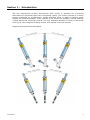
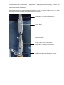
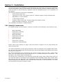
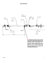
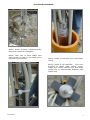
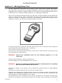
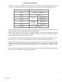
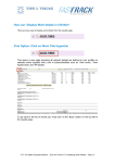
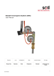
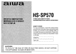
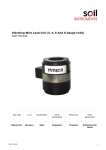
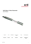
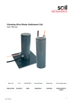
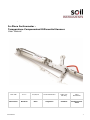
In-Place Inclinometer Temperature Compensated Differential Sensors User Manual Man 186 10.1.1. 07/08/14 Chris Rasmussen Andor Los Phil Day Chris Rasmussen Manual No. Revision Date Originator Checked Authorised for Issue User Manual 1 Contents Section 1 : Introduction .................................................................................................. 3 Section 2 : Installation.................................................................................................... 5 2.01 2.02 2.03 2.04 2.05 2.06 2.07 2.08 Identify Components ........................................................................................ 5 Attach Bottom Wheel And Rope.......................................................................... 8 Attach Gauge Extension Tube ............................................................................ 8 Lower First Sensor Into The Borehole .................................................................. 8 Attach Second Sensor ....................................................................................... 8 Lower Second Sensor Into The Borehole .............................................................. 9 Attach And Lower Subsequent Sensors................................................................ 9 Last Sensor And Suspension Tube Assembly ........................................................ 9 Section 3 : Wiring/Setup tool ....................................................................................... 10 Section 4 : Taking Readings/Logger Programming ....................................................... 12 Section 5 : Data Reduction ............................................................................................ 15 Section 6 : Sample Installation Record Sheet ................................................................ 16 Section 7 : Sample Calibration Sheet ............................................................................ 17 User Manual 2 Section 1 : Introduction The Soil Instruments In-Place Inclinometer (IPI) sensor is designed for monitoring deformations in boreholes fitted with inclinometer casing. The system consists of a sensor housing containing an accelerometer, gauge extension tubes to make up defined gauge lengths and wheel assemblies. Three versions of the sensor are available; vertical uniaxial, vertical biaxial and horizontal uniaxial. The only difference between versions is the sensor housing, all other components being shared. This manual covers all versions. Diagram Showing IPI Axis Orientation User Manual 3 Fundamental to the performance of IPI sensors is quality inclinometer casing, such as Soil Instruments EC casing, correctly installed. For details of suitable casing please see the Soil Instruments casing datasheets The components of the system are identified below, note: the system is built up on site from the components identified as it is placed into the borehole:- Gauge rod to next wheel/sensor combination (above current sensor) Sensor Body Wheel assembly Gauge rod to next wheel/sensor combination (below current sensor) Clamp holding IPI string in borehole during installation (optional, please see section 2.02 onwards) User Manual 4 Section 2 : Installation This manual covers the installation of the IPI sensors only and does not cover the installation of the inclinometer casing. If the sensors are being fitted into recently installed casing, care must be taken to ensure that any hydration heat has dissipated prior to the installation of the sensors. The following tools are required for installation 3mm & 5mm Allen keys Two pairs of ‘mole’ (vice) grips, and/or 2 x 200mm lengths of 5mm diameter bar Adjustable or 10mm spanner 3 metre tape measure Length of 5mm nylon rope 5 metres longer than depth of hole Small flat blade screwdriver (for wiring) The installation procedure is detailed below:- 2.01 Identify Components An installed string (in this example 3 sensors) consists of the following, from bottom to top; Wheel Assembly Sensor No:1 Housing Gauge Extension Wheel Assembly Sensor No:2 Housing Gauge Extension Wheel Assembly Sensor No:3 Housing Suspension Tube Assembly Please refer to the drawing on page 5 and the photos on pages 3 & 6 to help identify the above components. The wheel assemblies and the gauge extension tubes are attached using supplied allen bolts. Lay out all of the components of the system and ensure that all parts are present and correct (see figure on page 5). The wheel assemblies are connected to the sensor housing using two M6 x 20mm Allen bolts. The fixed wheel should point towards the A+ or positive direction of movement – see the label on the sensor body to identify this. The Sensor body is attached to the extension gauge tube using a M6 x 25mm Allen bolt and nut. The top sensor is connected to the suspension tube assembly using a M6 x 25mm Allen bolt and nut, this top tube has a non-articulating joint at the top which allows an inverted wheel assembly to be attached. This inverted wheel assembly is then attached to the solid rod that passes through the plastic hanger. User Manual 5 IN-PLACE INCLINOMETER Sensor Biaxial C12 - 1.3 5º Cable C12 - 1.4 10º Cable M6 x 25mm Allen Bolt & Nut M6 x 20mm Allen Bolt & Nut Extension Gauge Tube C12 - 2.1 1m C12 - 2.2 2m C12 - 2.3 3m Signal Cable CA - 3.1 - 4 - 1c Uniaxial CA - 3.1 - 6 - 1c Biaxial Gauge Length Wheel Assembly Sensor Uniaxial C12 - CF - 1.1 5º Radio C12 - 1.1 5º Cable C12 - 1.2 10º Cable Non-articulating joint C12 - 3.1 M6 x 20mm Allen Bolt & Nut Suspension Tube Assembly C12 - 4.1 1m C12 - 4.1 2m C12 - 4.2 3m Note: Although too small to be clearly seen at this scale. There is a 6mm diameter hole in the rod at the position arrowed to make installation of the IPI string in vertical and inclined holes easier. Simply slip a 5mm x 200mm (approx) long diameter rod through the hole to prevent the IPI string falling down the borehole User Manual 6 IN-PLACE INCLINOMETER Above: Detail of gauge rod/wheel/sensor body built up prior to installation Below: Take care to dress cables from lower sensors so they do not obstruct the operation of the wheels Above: Detail of insertion into inclinometer casing Below: Detail of top assembly – note even dressing of cables (GRP version shown, Gauge Rod version identical but with larger clamp hole to accommodate stainless steel Gauge Rod) User Manual 7 IN-PLACE INCLINOMETER 2.02 Attach Bottom Wheel and Rope Any wheel assembly can be used as the bottom wheel. Each wheel assembly has one fixed and one sprung loaded wheel, the fixed wheel should be in the A+ (+mm) direction of the sensors. The A+ (+mm) direction is identified on the sensor body. Using the supplied Allen bolts, attach the wheel to the bottom of the first sensor, hold the Nylock nut with the spanner and tighten the Allen bolts using the Allen key, do not over tighten. Remember, all sensors have cables exiting from their top. It is strongly recommended, but not mandatory to fit a rope to the lowest sensor in the string to aid with removal and to act as a safety device should the assembly slip and/or the sensor string accidentally be dropped into the borehole. If rope is to be used, tie it around the gauge extension rod with a loose noose knot. 2.03 Attach Gauge Extension Tube Using the supplied Allen bolts (M6x25mm) attach the gauge extension tube to the top (where the cable exits) of the first sensor, again, use the spanner to hold the Nylock nut in place and do not over tighten. Repeat steps 2 and 3 above for each sensor in the string so you have complete, built up sensors. Lay these out in the order of installation (normally dictated by serial numbers for neatness, but not mandatory) and lay the cables out so they will not become tangled or snagged during installation and are free to move down the borehole. You may wish to use cable ties during installation to keep the cable from snagging to the gauge lengths. 2.04 Lower First Sensor into The Borehole Place the 5mm diameter rod through the hole at the end of the gauge extension rod, just below where the next wheel set will be attached so that the 5mm rod spans the inclinometer casing and prevents the sensor from falling into the borehole. If not using a 5mm rod, set the mole grips so that they firmly grip the extension tube, approx. 100mm below the upper end, without deforming the tube. The purpose of the rod and or grips is to prevent the sensor falling into the borehole and to allow subsequent sensors to be fitted with ease. As more sensors are added, ensure that the rod and or the grips to not crush the cables as they exit the borehole. Immediately prior to lowering the sensor into the borehole, make a note of its serial number, position in string and depth on an installation sheet. A sample sheet is attached at the end of this manual. Locate the A+ (+mm) direction and lower the sensor, bottom wheel first, gently into the borehole with the fixed wheel facing towards this direction, i.e. the fixed wheel should be facing the direction of movement, the sprung wheel away from the direction of movement, taking care to ensure that the cable is not stretched, snagged or kinked, until the 5mm rod or the grips are resting on the top of the borehole. Make sure that the cable is laid out in such a way that as subsequent sensors are added it can freely and smoothly move down the borehole. If rope is being used, ensure that this too is freely in the hole and not snagging the wheels. 2.05 Attach Second Sensor Place the bottom of the wheel assembly for the second sensor into the fitting at the top of the gauge extension tube from the first sensor, now held in the borehole by the 5mm diameter rod and or grips. Ensure that the sensor and the fixed wheel will be in the correct (A+ / +mm) orientation when the sensor is raised to vertical (see 6 below) to lower into the borehole. Using the Allen key and the spanner fit the Allen bolt to the Nylock nut taking care not to over tighten. Place a second 5mm diameter rod in the next gauge tube hole, or the second pair of grips approx. 100mm below the top of the second sensor extension tube as described in 4 above. User Manual 8 IN-PLACE INCLINOMETER 2.06 Lower Second Sensor into the Borehole Immediately prior to lowering the sensor into the borehole, make a note of its serial number, position in string and depth on an installation sheet. A sample sheet is attached at the end of this manual. Raise the second sensor to a vertical position with one hand, whilst holding the lower 5mm diameter rod or set of grips with the other hand. When the second sensor is vertical, remove the lower 5mm diameter rod, or release the lower pair of grips and gently lower the second sensor into the borehole until the upper (only) 5mm diameter rod or pair of grips is now supporting both sensors in the borehole. Take care to ensure that the wheels remain in the grooves and that they are not snagged by the cable or the rope (if used) both of which should be free to move within the borehole. 2.07 Attach and Lower Subsequent Sensors Repeat steps 5 and 6 above until all but the last (top) sensor is installed, refer to 8 below for the last sensor and Suspension Tube Assembly, do not forget to make a note of serial number, string position and depth for each sensor. 2.08 Last Sensor and Suspension Tube Assembly The Suspension Tube Assembly supports the string in a vertical borehole and maintains its position in a horizontal hole. The Suspension Tube Assembly does not require orientation and has cut outs to allow for cable exit (more than one of these can be used if desired) Measure the desired distance from the fixed wheel on the Suspension Tube Assembly to the desired location for the top support and then secure the support at this point. The support is fitted by tightening the two Allen headed screws within the clamp ring. Care must be taken to ensure that these are tight enough to support the weight of the string in a vertical borehole, but not too tight thus risking damage to the screw threads. Once in position, fit a pair of grips approx. 100mm above the support assembly. Place the final sensor suspension tube assembly into the fitting at the top of the penultimate sensor gauge extension as before, raise and lower that last sensor into the borehole. Take great care to ensure that the cables are not trapped between the top assembly and the casing and that they pass freely through the openings in the top assembly. Centralise the assembly in the top of the hole and once satisfied that it is secure and release the grips. If a rope has been used, cut to length so approx. 2.5 metres is left at the top of the hole, neatly coil and tape or cable tie to the inclinometer casing. Occasionally, where a borehole is under depth, the top sensor will not fully fit into the borehole at the desired gauge length. In this case, withdraw the last sensor and reposition the support by moving it closer to the wheel assembly of the top sensor. User Manual 9 IN-PLACE INCLINOMETER Section 3 : Wiring/Setup Tool The Soil Instruments IPI sensor can be read by most commercially available dataloggers. Soil Instruments recommend the Campbell datalogger range and can supply a fully built up datalogger with enclosure, logging program and a variety of communications options from a simple direct link to satellite modem, please see our datalogger datasheets. We do not recommend that IPI sensors are read with a manual readout as this defeats the object of in-place sensors, where a traditional traversing probe inclinometer should be used, however if desired, a voltmeter can be used. (An external 12-16VDC power supply will be needed to do this) or our IPI set up tool part number 1132-600. To Use the setup tool connect the red wire from the IPI to the +V terminal on the setup tool and the black wire from the IPI to the –V terminal. The tool can only read 1 axis at a time. For the A axis connect the white wire from the IPI to the +SIG terminal and the green wire from the IPI to the –SIG terminal. WARNING Ensure the remaining wires are not shorting together or to any other wire. Press the on/off button to switch the readout on. The IPI reading in mV will be displayed on the screen. WARNING Ensure the readout is switched off before removing wires or replacing the A axis wires with the B axis wires. The battery voltage of the readout can be checked by pressing down the Sensor/Battery button. The battery should be replaced when its volts are less than 8.5V. Whatever the datalogger or reading method, the wiring remains the same. The sensors are supplied with a polyurethane-jacketed 4-core cable (6 for bi-axial sensors) suitable for long term immersion in water at depths of up to 200m. The cable has four or six conductors, a foil, screen and drain wire. The drain wire and screen should be connected to the ground terminal at the sensor input terminals for maximum User Manual 10 IN-PLACE INCLINOMETER resistance to induced voltages and interference. The sensor is a differential device and thus a + and – reading must be taken. The conductor colour codes are as per the table below:Conductor Colour Identification Red Power+ (10-16VDC) Black Ground White Green Signal High A axis Signal Low Blue B axis Signal High Yellow (bi-axial sensor) Signal Low Bare Wire Drain (Screen) Take extreme care whilst wiring to ensure conductors are correctly wired, especially the red power conductor. Always wire with the power switched off. When using Bi-axial sensors with a Campbell AM416 or AM16/32 multiplexers, please contact Soil Instruments if assistance is needed in wiring to meet the CR10/CR1000 logger protocols detailed in Section 4 of this manual. If it is desired to check the functioning of the sensors immediately after installation, at zero degrees tilt (i.e. true vertical or horizontal), the sensor output is approximately 0VDC. When wiring into a datalogger it is good practice to wire the lowest sensor to the first channel, the second sensor to the second channel etc. If a program not supplied by Soil Instruments is being used the following protocol should be observed to obtain the best results. Power sensors on, wait for 3 seconds; take a minimum of 50 readings (differential voltage) at minimum 100 millisecond intervals and average. User Manual 11 IN-PLACE INCLINOMETER Section 4 : Taking Readings/Logger Programming The Soil Instruments IPI sensors are designed to be read by Campbell datalogger systems. Other dataloggers can be used, including the Campbell CR1000 loggers, but the basic reading and excitation architecture outlined in this section must be followed. Sensors should be read via a multiplexer (Campbell AM416 or AM16/32) and the following sequence must be used to ensure best sensor performance: - Activate multiplexer - Switch to first channel a) Switch on power supply to sensor (on Campbell loggers use the Switched 12Volt option) b) Let the sensor warm up for at least 3 seconds c) Take a minimum of 50 differential measurements and store the average d) Switch power to the sensor off e) Switch to the next channel NOTE: - Repeat step a) through e) for the next sensor - De-activate multiplexer a sample program for a CSI CR10X unit is printed below – for CR800 and CR1000 programs, please contact Soil Instruments. Sensors can be left powered when not being read, but for maximum life we do not recommend this. When using multiplexer units this is not possible and the above sequence should be observed. When long cables are used make sure to increase the settling time for the datalogger measurements to achieve optimal performance. These sample CR10X instructions below assume:C1 = Act-multiplexer 1 C7 = Act Switched 12Volt C8 = CLK pulse for multiplexer Measuring channel is differential channel 1 Multiplexer = CSI AM16/32 (in 4x16 mode) ; Set C8 for CLK pulse ; Activate multiplexer 1 on C1 1: Set Port(s) (P20) 1: 4000 C8..C5 = 10ms/low/low/low 2: 0001 C4..C1 = low/low/low/high ; Start a loop for 16 IPI sensors Uni-axial or 8 IPI sensors Bi-Axial 2: Beginning of Loop (P87) 1: 0000 Delay 2: 16 Loop Count User Manual 12 IN-PLACE INCLINOMETER ; Send a CLK pulse 3: Do (P86) 1: 78 Pulse Port 8 ; Activate SW12Volt 4: Do (P86) 1: 47 Set Port 7 High ; Let the sensors warm up for at least 3 seconds 5: Excitation with Delay (P22) 1: 3 Ex Channel 2: 0000 Delay W/Ex (0.01 sec units) 3: 300 Delay After Ex (0.01 sec units) 4: 0 mV Excitation ; Start a loop for 50 measurements 6: Beginning of Loop (P87) 1: 0000 Delay 2: 50 Loop Count ; Measure the sensors differential on channel 1 7: Volt (Diff) (P2) 1: 1 Reps 2: 5 2500 mV Slow Range 3: 1 DIFF Channel 4: 2 -- Loc [ measmV_01 ] 5: 1.0 Multiplier 6: 0.0 Offset 8: End (P95) ; De-Activate the SW12Volt 9: Do (P86) 1: 57 Set Port 7 Low ; Take the Average of the measurements and store it 10: Spatial Average (P51) 1: 50 Swath 2: 2 First Loc [ measmV_01 ] 3: 1 -- Avg Loc [ IPImV_01 ] ;End of Loop 11: End (P95) ;De-Activate multiplexer 1 12: Do (P86) 1: 51Set Port 1 Low ;Do other processing here User Manual 13 IN-PLACE INCLINOMETER …………… ;Then store the data If in any doubt we recommend contacting Soil Instruments for advice. The performance of the sensors as calibrated is not guaranteed unless the above protocols are used. Soil Instruments can supply full logger programs and wiring diagrams at an extra cost, please contact us for details. User Manual 14 IN-PLACE INCLINOMETER Section 5 : Data Reduction The Soil Instruments IPI sensor is calibrated over ±5 or ±10 arc degrees (approx. ±87 or ±175mm/metre) and has a DC voltage output dependant on tilt. The sensors are calibrated for tilt only (please see note on temperature below) and the unit of calibration (either Arc Degrees or mm/metre) is specified at the time of order. The calibration certificate supplied with the sensor (please see section 6) contains the following information: Instrument Type Serial Number Range Calibration Data (both raw and reduced) Conversion Formula FS Error % at each calibration point Wiring Code NOTE Once the polynomial formula has been calculated the resultant must be multiplied by the gauge length of the sensor, measured during installation, to give correct cumulative deflection calculations, unless only individual arc degree rotations are required. A positive resultant indicates movement towards the A+ (+mm) direction; a negative resultant indicates movement towards the A- (-mm) direction. The calibration factors can easily be loaded into a spreadsheet and data added via cut and past or an automated program such as I-Site can be used, in which case the application of calibration factors and gauge length is fully automatic. The MEMS Accelerometer chip used in the IPI sensor is calibrated for temperature as part of the micro-machine manufacturing process by the chip manufacturer. As well as the MEMS tilt element the sensor contains a microprocessor and a look up table to apply correction for temperature changes to the silicon substrate within the sensing element. Soil Instruments has no control over this process other than by the QA procedures followed by the chip manufacturer, which specify the correction and rejection criteria. The sensor output is therefore corrected automatically for the effects of temperature on the accelerometer chip. Please note that this correction will not apply to unknown factors within the sensor string or borehole where an external change may well be occurring. Soil Instruments do not offer the sensor with an on-board temperature sensor. If borehole temperature measurement is desired, then a separate temperature sensor must be installed additional to the IPI sensor. User Manual 15 IN-PLACE INCLINOMETER Section 6 : Sample Installation Record Sheet In-Place Inclinometer Installation Record Sheet Date Installer Site A+ Direction Borehole ID Casing Size Depth No: Of Sensors Depth User Manual Sensor Number Serial Number Gauge Length Notes 16 IN-PLACE INCLINOMETER Section 7 : Sample Calibration Sheet Bell Lane, Uckfield, East Sussex t: +44 (0) 1825 765044 e: [email protected] TN22 1QL United Kingdom f: +44 (0) 1825 744398 w: www.itmsoil.com Soil Instruments Ltd. Registered in England. Number: 07960087. Registered Office: 5th Floor, 24 Old Bond Street, London, W1S 4AW User Manual 17