1
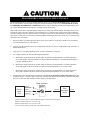
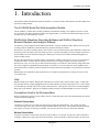
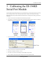
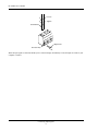
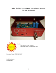
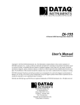
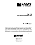
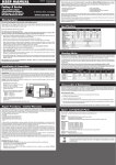
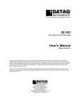
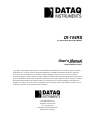
The way PC-based instrumentation should be
DI-194RS
4-Channel Data Acquisition Module
User'sManual
Manual
Revision H
Software Release Level 1
Copyright © 2006 by Dataq Instruments, Inc. The Information contained herein is the exclusive property of Dataq
Instruments, Inc., except as otherwise indicated and shall not be reproduced, transmitted, transcribed, stored in a
retrieval system, or translated into any human or computer language, in any form or by any means, electronic,
mechanical, magnetic, optical, chemical, manual, or otherwise without expressed written authorization from the company. The distribution of this material outside the company may occur only as authorized by the company in writing.
Dataq Instruments' hardware and software products are not designed to be used in the diagnosis and treatment of
humans, nor are they to be used as critical components in any life-support systems whose failure to perform can reasonably be expected to cause significant injury to humans.
241 Springside Drive
Akron, Ohio 44333 U.S.A.
Telephone: 330-668-1444
Fax: 330-666-5434
Designed and manufactured in the
United States of America
Warranty and Service Policy
Product Warranty
DATAQ Instruments, Inc. warrants that this hardware will be free from defects in materials and workmanship under
normal use and service for a period of 90 days from the date of shipment. DATAQ Instruments' obligations under this
warranty shall not arise until the defective material is shipped freight prepaid to DATAQ Instruments. The only
responsibility of DATAQ Instruments under this warranty is to repair or replace, at its discretion and on a free of
charge basis, the defective material.
This warranty does not extend to products that have been repaired or altered by persons other than DATAQ Instruments employees, or products that have been subjected to misuse, neglect, improper installation, or accident.
DATAQ Instruments shall have no liability for incidental or consequential damages of any kind arising out of the sale,
installation, or use of its products.
Service Policy
1.
All products returned to DATAQ Instruments for service, regardless of warranty status, must be on a freight-prepaid basis.
2.
DATAQ Instruments will repair or replace any defective product within 5 days of its receipt.
3.
For in-warranty repairs, DATAQ Instruments will return repaired items to the buyer freight prepaid. Out of warranty repairs will be returned with freight prepaid and added to the service invoice.
iii
CAUTION
!
!
READ BEFORE CONNECTING INPUT SIGNALS
The data acquisition device you have purchased and are about to use is NOT an ISOLATED product. This means
that it is susceptible to common mode voltages that could cause damage to the device. SUCH DAMAGE IS NOT
COVERED BY THE PRODUCT’S WARRANTY. Please read the following carefully before deploying the product. Contact DATAQ Instruments Support at 330-668-1444 for all questions.
This product can tolerate a maximum applied voltage of only ±20V peak without damage. Although you may be certain that the signal you want to measure is lower than this level, a common mode voltage (CMV) with an unknown
value may combine with your signal of interest to exceed this ±20V limit. In such instances, the product will be damaged. Verify a CMV does not exist before connecting signals and acquiring data with your device. Use the following
procedure to check for CMV:
1.
DO NOT connect your data acquisition device to the device under test. If the device under test is connected to
your data acquisition device, disconnect it.
2.
Connect your data acquisition device to the appropriate interface on your PC (USB, Ethernet, RS-232 Serial, or
Parallel Printer Port).
3.
Apply power to your data acquisition device, your PC, and the device under test.
4.
Use a digital voltmeter to make the following measurements:
5.
a.
Measure the voltage (both the AC and DC range) between the ground terminal of your data acquisition
device and Signal+ of the device under test. This measurement should not exceed the Full Scale Range of
your data acquisition device.
b.
Measure the voltage (both the AC and DC range) between the ground terminal of your data acquisition
device and Signal- of the device under test. This measurement should be at or very near 0 Volts.
c.
Measure the voltage (both the AC and DC range) between the ground terminal of your data acquisition
device and Common of the device under test. This measurement should be at or very near 0 Volts.
Should ANY of these measurements exceed their recommendation DO NOT CONNECT SIGNALS to the data
acquisition device. A common mode voltage may exist that could destroy the instrument. You MUST determine
the source of the CMV and eliminate it before taking any measurements.
Digital Voltmeter
Signal +
Device
Under
Test
1
Ground4
Signal - 2
Common3
1Measured
signal is not to exceed the Full Scale Range of your data acquisition device.
Measured signal must be at or very near 0 volts.
3Measured signal must be at or very near 0 volts.
4Connect to GND (Analog Ground) port on DI-194RS instruments.
2
v
Data
Acquisition
Device
To PC
DI-194RS User’s Manual
Table of Contents
Warranty and Service Policy ................................................................................................................ iii
1. Introduction ....................................................................................................................................... 1
The DI-194RS Serial Port Data Acquisition Module ........................................................................ 1
WinDaq/Lite Waveform Recording Software and WinDaq Waveform Browser Playback and Analysis
Software ...................................................................................................................................... 1
Help ................................................................................................................................................... 1
Conventions Used in the Documentation .......................................................................................... 1
General Conventions ................................................................................................................... 1
Mouse Conventions ..................................................................................................................... 1
WinDaq Operating Modes ................................................................................................................. 2
2. Getting Started .................................................................................................................................. 3
Connecting the DI-194RS to Your Computer ................................................................................... 3
Installing WinDaq Software .............................................................................................................. 3
Menu Items Created During Installation ..................................................................................... 4
3. Calibrating the DI-194RS Serial Port Module ............................................................................... 5
4. Connecting Your Input Signals to the DI-194RS ........................................................................... 7
Table of Contents
vii
DI-194RS User’s Manual
1. Introduction
This manual contains information designed to familiarize you with the features and functions of the DI-194RS serial
port data recording module.
The DI-194RS Serial Port Data Acquisition Module
The DI-194RS is a portable data recording module that communicates through your computer's RS-232 (or serial)
port. It features four single-ended analog inputs, three digital inputs, a ±10V full scale measurement range, and can
record at rates up to 240 samples per second.
WINDAQ/Lite Waveform Recording Software and WINDAQ Waveform
Browser Playback and Analysis Software
The WINDAQ software shipped with all DATAQ Instruments’ serial port products includes WINDAQ/Lite waveform
recording software and WINDAQ Waveform Browser playback and analysis software.
WINDAQ/Lite waveform recording software can be used to record waveforms directly and continuously to disk while
monitoring a real time display of the waveforms on-screen. It operates and displays waveform signals in real time at
the full sample rate of the instrument being used. WINDAQ/Lite is limited to a 240 Hz maximum throughput rate
when recording to disk.
WINDAQ Waveform Browser playback software (also known as “WWB”) offers an easy way to review and analyze
acquired waveforms. A built-in data file translator allows the user to display multiple waveforms acquired by
WINDAQ/Lite or any of a wide range of data acquisition packages. The software’s disk-streaming design allows data
files of any length to be graphically displayed rapidly, in normal or reverse time directions. Seven standard cursorbased measurements, frequency domain, and statistical analysis functions help simplify waveform analysis and interpretation.
Both WINDAQ/Lite and WINDAQ Waveform Browser are available for download free-of-charge from our web site
(www.dataq.com).
Help
Both the WINDAQ/Lite and the WINDAQ Waveform Browser software utilize context-sensitive help. For help with
any particular function, simply highlight the menu item in the WINDAQ software and press the F1 key. This will take
you immediately to the help topic most relevant to that menu item. The help files may also be accessed through the
Help menu in the Software. Help files are updated regularly and may be installed through our web site if desired.
Conventions Used in the Documentation
Before using WINDAQ software, please read this section to understand some of the terms and notational conventions
used here and in the Help Files.
General Conventions
Commands you choose are given with the menu name preceding the command name. For example, the phrase
“Choose File Open” tells you to choose the Open command from the File menu. This naming convention describes
the sequence you follow in choosing a command - first you select the menu, then you choose the command.
Mouse Conventions
In general, most mouse actions require only the left mouse button. For example, carrying out a menu command or
working in a dialog box requires only the left mouse button. Since the majority of mouse procedures are done with
Introduction
1
DI-194RS User’s Manual
the left mouse button, we will not specify which mouse button to click, drag, or double-click in the procedure unless
the action uses the RIGHT mouse button. For example, “Double-click the right mouse button anywhere in the bottom
annotation line to move the cursor to the lowest displayed waveform valley.”
•
“Point” means to position the mouse pointer until the tip of the pointer rests on what you want to point to on the
screen. For example, “Point to the View menu.”
•
“Click” means to press and immediately release the mouse button without moving the mouse. For example, “To
display the menu that contains the command you want, click the menu name in the menu bar.”
•
“Double-click” means to click the mouse button twice in rapid succession. For example, “Double-click the icon
to start the program.”
•
“Drag” means to press the mouse button and hold it down while you move the mouse; then release the button.
For example, “Drag down to Data Cursor to enabled the cursor for on-screen display.”
WINDAQ Operating Modes
WINDAQ waveform recording software has three operating modes: Setup, Record, and Standby. Each operating
mode shares many features with the other two, but specific modes may restrict features or disable some functions
altogether.
WINDAQ Recording Software starts in the SET UP operating mode. In SET UP mode you can configure data acquisition parameters—such as the number of acquired channels, channel gain, and channel offset—and customize the
real time display. SET UP operating mode provides access to most data acquisition functions and adjustments including control of the real time display screen's scaling and offset functions. The SET UP mode displays data in real time
but does not store data to disk. This mode limits sample rate only by the capabilities of the hardware. In other words,
you can sample as fast as your instrument will allow. When in this mode, the Status: area of the bottom annotation
line displays SET-UP.
The RECORD operating mode stores, or streams, data to disk. Activate the RECORD mode by selecting Record
from the File menu. You can use all waveform recording features and functions (with some restrictions) while in the
RECORD mode except the following: Channel-specific operations (i.e., channel number, gain, offset) and sample
rate adjustments. Waveform information continuously streams to disk while the real time display remains active.
RECORD mode limits sample rate to 240 Hz maximum throughput when using WINDAQ/Lite but does not limit the
sample rate when using WINDAQ/Pro or Pro+ (limit determined by hardware). When in RECORD mode, the Status:
area of the bottom annotation line displays RECORD.
Use the STANDBY operating mode to temporarily suspend (pause) waveform recording to disk. Select Stop in the
File menu to enter STANDBY mode. You can use all waveform recording features and functions except channel-specific operations (i.e., channel number, offset, etc.) and sample rate adjustments. The STANDBY mode displays data
in real time while waveform recording to disk has been stopped. When in this mode, the Status: area of the bottom
annotation line displays STBY. Start and stop as many times as desired during a data acquisition session.
Introduction
2
DI-194RS User’s Manual
2. Getting Started
The following items are included with each WINDAQ Starter Kit. Verify that you have the following:
•
DI-194RS instrument.
•
CD containing WINDAQ software, this documentation, our full-line catalog, various articles, and application
notes.
•
Communications cable designed to connect the instrument to your computer’s serial port.
•
Screwdriver for securing your signal leads into the screw terminal inputs.
If an item is missing or damaged, call DATAQ Instruments at (330) 668-1444. We will guide you through the appropriate steps for replacing missing or damaged items. Save the original packing material in the unlikely event that your
unit must, for any reason, be sent back to DATAQ Instruments.
Connecting the DI-194RS to Your Computer
The DI-194RS can be connected directly to your PC's serial (or COM) port, no cable is required. If you would like
more accessibility and/or convenience than what the direct-connection provides, you can use any standard 9-pin
serial cable (included). Just connect the male end of the serial cable to the DI-194RS and connect the other end of the
cable to your computer's serial port. DO NOT CONNECT INPUT SIGNALS TO YOUR DEVICE UNTIL YOU
HAVE READ “CAUTION” on page v.
Installing WINDAQ Software
1.
Insert the WINDAQ Resource CD into your CD-ROM drive and close the drive tray. For most users, the Windows’ auto-run feature will automatically display a list of options. If you do not see this list of options after a reasonable period of time, double-click the My Computer icon on your desktop and then double-click your CDROM icon to manually display the list of options.
2.
Choose the “Install Software for Starter Kits (DI-154, DI-194, DI-195B)” radio button and click OK.
3.
Choose the “Install WinDaq Starter Kit Software for the DI-194” radio button and click OK.
4.
The Welcome dialog box allows you to cancel the installation. Click OK to continue.
5.
Read the License agreement and either “Accept and Continue” to continue the installation or “Do not accept and
stop” to cancel the installation.
6.
Select the folder (default is C:\DATAQ) you would like to place the files in and click OK.
7.
Select the Program Manager Group to save shortcuts to in the Windows Menu. The default is WINDAQ.
8.
Specify the COM port you have connected the Starter Kit to and click OK. Be sure to have to correct COM Port
specified. Installing to a nonexistent COM Port or to an incorrect COM Port requires the software to be uninstalled and re-installed.
9.
Installation is complete. Click OK to exit the installation program.
Both WINDAQ/Lite and WINDAQ Waveform Browser may be run from the Windows Menu as specified in Step 7
above (default is Start > Programs > WINDAQ).
Getting Started
3
DI-194RS User’s Manual
Menu Items Created During Installation
The Sample Files Folder contains 8 different sample files to illustrate the versatility of WINDAQ Software. These
samples are WINDAQ Waveform Browser Files that can be measured, analyzed, and manipulated in any way that you
please.
The Add-Ons Folder provides access to the add-on program WINDAQ XY Viewer. This program allows the user to
generate a multi-channel XY plot in real time.
The WINDAQ Lite Data Acq DI-194 icon runs the WINDAQ/Lite Data Acquisition Software.
The WINDAQ Waveform Browser icon runs the WINDAQ Waveform Browser Software.
The How to program DI194 icon links to the UltimaSerial internet page providing information for programming the
DI-194.
The License icon provides the Software Agreement License in text format.
The Meter icon runs the Meter software which may be run while WINDAQ/Lite is running. This program reports
waveform data values in a digital display format.
Getting Started
4
DI-194RS User’s Manual
3. Calibrating the DI-194RS
Serial Port Module
Your DI-194RS serial port module initially arrives in an uncalibrated state. You must perform this initial “fine tuning”
before recording waveforms to disk. Since this procedure requires a voltmeter, have it handy before starting.
With the DI-194RS serial port module installed and with WINDAQ/Lite recording software running, perform the following steps:
1.
Connect a wire between CH1 and GND on the DI-194RS serial port module.
2.
Select channel 1 by clicking the left mouse button in the channel's annotation margin. Channel 1 is enabled for
modifications when a box surrounds the “1=1” equality in the annotation margin.
3.
Click on Low Calibration… in the Edit menu. This displays the Low Calibration dialog box:
4.
Enter 0 (zero) in the Low Cal Value text box and click OK.
5.
Repeat steps 1 through 4 for channels 2, 3, and 4.
6.
Now connect a wire between CH1 and Dig1 on the DI-194RS serial port module.
7.
Using a voltmeter, measure and record the voltage between the CH1 and GND terminals.
Calibrating the Instrument
5
DI-194RS User’s Manual
8.
With channel 1 selected (step 2), click on High Calibration… in the Edit menu. This displays the High Calibration dialog box. The values entered for the Low Calibration will appear here.
9.
Enter the value measured in step 7 in the High Cal Value text box and click OK.
10. Click on Limits… in the Scaling menu. This displays the Channel 1 Display Limits dialog box:
11. Enter 10 in the Top Limit text box and -10 in the Bottom Limit text box and click OK.
12. Repeat steps 6 through 11 for channels 2, 3, and 4.
13. From the File menu, select Save Default Setup. This saves the calibration constants you just entered and makes
them available for all subsequent recording sessions.
Note: If connecting a sensor with a known relationship between volts and engineering units select the Use Previous
Cal. checkbox before entering sensor Input Levels and Calibration Values. Select Edit > Preferences > Allow Relative Calibration in the WinDaq program menu to enable the Use Previous Cal. checkbox.
Calibrating the Instrument
6
DI-194RS User’s Manual
4. Connecting Your Input Signals to the DI-194RS
DO NOT CONNECT INPUT SIGNALS TO YOUR DEVICE UNTIL YOU HAVE READ “CAUTION” on
page v. All input signal connections are made to the 8-port screw terminal. Each terminal is labeled directly on the
circuit board. Refer to the following for screw terminal port identification:
CH 1: Channel 1 analog signal input.
CH 2: Channel 2 analog signal input.
CH 3: Channel 3 analog signal input.
CH 4: Channel 4 analog signal input.
Gnd: Ground.
Dig 0: Digital port 0.
Dig 1: Digital port 1.
Dig 2: Digital port 2.
To connect signals to the DI-194RS, insert the stripped end of a signal lead into the desired terminal directly under the
screw. Tighten the pressure flap by rotating the screw clockwise with a small screwdriver. Make sure that the pressure flap tightens only against the signal wire and not the wire insulation. Do not over-tighten. Tug gently on the signal lead to ensure that it is firmly secured.
Connecting Input Signals
7
DI-194RS User’s Manual
Loosen
Tighten
Screwdriver
Signal lead
Pressure flap
When an input signal is connected, WINDAQ/Lite’s real time display immediately reveals the input waveform on your
computer’s monitor.
Connecting Input Signals
8
DATAQ Instruments, Inc.
241 Springside Drive
Akron, Ohio 44333
Telephone: 330-668-1444
Fax: 330-666-5434
E-mail: [email protected]
Direct Product Links
(click on text to jump to page)
Data Acquisition | Data Logger | Chart Recorder | Thermocouple | Oscilloscope