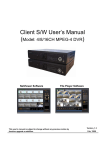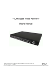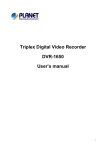
1
DiViS CHSM48016 - Stand Alone Installation and User’s Guide Rev. 2.0 Digital Video Security System Digital Video Recorder www.DiViSdvr.com Chance-i USA Corp. * All contents of this document may change without prior notice, and actual product appearance may differ from that depicted herein. www.DiViSDVR.com Safety Precaution CAUTION CAUTION RISK OF ELECTRIC SHOCK DO NOT OPEN CAUTION: TO REDUCE THE RISK OF ELECTRIC SHOCK, DO NOT REMOVE COVER (OR BACK). NO USER SERVICEABLE PARTS INSIDE. REFER SERVICING TO QUALIFIED SERVICE PERSONNEL. This label may appear on the rear of the unit due to space limitations. The lightning flash with arrow point symbol, within an equilateral triangle, is intended to alert the user to the presence of uninsulated “dangerous voltage” within the product’s enclosure that may be of sufficient magnitude to constitute a risk of electric shock to persons. The exclamation point within an equilateral triangle is intended to alert the user to the presence of importance operating and maintenance (servicing) instructions in the literature accompanying the appliance. Warning To reduce the risk of fire or electric shock, Do not expose this product to rain or moisture. Do not insert any metallic object through ventilation grills. Power disconnect: Units with or without ON-OFF switches have power supplied to the unit whenever the power cord is inserted into the main source. To disconnect it from the main source, you have to disconnect the Power cord. v 2 DiViS www.DiViSDVR.com FCC COMPLIANCE STATEMENT A CLASS A computing device subject to certification by the Commission shall be identified pursuant to Par 2.925 et Seq of the chapter. In addition, the label shall include the following statement: This device complies with Part 15 of FCC Rules. Operation is subject to the following two conditions: (1)This device may not cause harmful interference, and (2)This device must accept any interference received, including interference that may cause undesired operation. Where a device is constructed in two or more sections connected by wires and marked together, the statement specified in this Section is required to be affixed only to the main control unit. The user’s manual or instruction manual for the EUT shall contain the following statement or equivalent. Caution: Changes or Modifications not expressly approved by the party responsible for compliance could void the user’s authority to operate the equipment. If the EUT requires accessories such as special shield cables and/or connectors to enable compliance with emission limits, the instruction manual for the EUT shall include appropriate instruction on the first page of the text concerned with the installation of the device that these special accessories must be used with the device. It is the responsibility of the user to use the needed special accessories supplied with the equipment. For a CLASS A digital device or peripheral, the instruction furnished the user shall include the following or Similar statement placed in a prominent location in the text of the manual. Note: This equipment has been tested and found to comply with the limits for a CLASS a digital device, pursuant to Part 15 of FCC Rules. These limits are designed to provide reasonable protection against harmful interference when the equipment is operated in a commercial environment, This equipment Generates, uses and can radiate radio frequency energy and, if not installed and used in accordance with the instruction manual, may cause harmful interference to radio communications. Operation of the this equipment in a residential area is likely to cause harmful interference in which cause the user will be required to correct the interference at his own expense. v 3 DiViS www.DiViSDVR.com Preface This document is a basic manual for the DiViS CHSM48016 users. The manual describes the appearance and name of products, how to configure the system program, and how to use the system. Please review the whole contents before using DiViS CHSM48016, and access the product with caution. The pictures and names of the products are subject to change depending on hardware upgrade. However, the usages may be similar. To open the system case and touch the inner parts for corrective maintenance, a user should contact the place where he/she purchased the products to get the help from expert. In addition, if there are any questions for use or any damage on the product, please contact the place where he/she purchased the products. The pictures and names of the products are subject to change without notification. However, the usages may be similar. For any questions you might have, please contact us through the Service Request form available online. When submitting your concerned matter, please include your company name and phone number with detailed descriptions. Service Request Link: http://www.divisdvr.com/divis/sp_service.asp Website: http://www.divisdvr.com v 4 DiViS www.DiViSDVR.com Warning on Installation and Usage 1. Warning on Installation • Install the product on a flat floor, open space, and keep the minimum of 6 inches distance from the rear panel to the wall. • Install the product on a well-ventilated place. • Keep it away from strong magnetism or electromagnetic wave. • Installing it near to radio equipment such as TV or radio may cause a malfunction. • Do not install it on a place directly exposed to the sun or other heating sources, such as near a heating apparatus. • Do not install it on a cold place. • While installing the equipment, keep the equipment and related tools in safe position to prevent any injury. • Do not install it on a place with constant vibration, high humidity, grease, or dust. • Should use the product in the rated voltage (The equipment requires DC 12V and the power supply included can be used for the voltage between 110V and 240V.) • Connect it to the outlet with the ground terminal. • Discard the vinyl bag well as it may be dangerous under a child’s hands. 2. Warning on Usage • For the repair, contact the company or the place where you purchased the product. • Read the user manual before using the products. • Do not open the cover at your discretion since parts are sensitive to the environment within the equipment. • Arrange the power cord safely and do not touch it with wet hands. • Do not use a loose outlet or a damaged power cable. • Do not use benzene, thinner and alcohol for cleaning. • Do not touch the exposed terminal. • To properly turn off the system, use the power button on the front panel before disconnecting the power supply. • Be careful to prevent a conductive object from falling into a hole that was punched for ventilation. • Do not disassemble nor remodel the product. • Do not place a heavy object on the body. • Handle with care while moving the equipment. In case of any smoke or odor emitted, immediately block the power switch and contact the company you purchased the products to consult it with a special technician. v 5 DiViS www.DiViSDVR.com Contents 1. Product Contents 7 2. Features 8 3. Product Description 9 3-1. Front Panel Connection 9 3-2. Rear Panel Connection 9 3-3. Front Panel Description 10 3-4. Rear Panel Description 12 3-5. Remote Controller 14 15 4-1. Overview Main Menu 15 4-2. DVR Menu Tree 16 4-3. System Setup 17 4-4. Display Setup 19 4-5. Recording Setup 20 4-6. Event Setup 21 4-7. Schedule Setup 23 4-8. Network Setup 24 4-9. Copy Setup 25 4-10. Hard Disk Setup 26 4-11. Camera Setup 27 5. Live Display & Recording 28 5-1. Live Picture Display Mode 28 5-2. OSD (On Screen Display) on Live Mode 29 5-3. PTZ Control 30 5-4. Recording Options 30 31 6-1. Search List 31 6-2. Search by Recording Type 32 6-3. Search by Time & Date 32 6-4. Playback 33 6-5. Backup 34 35 7-1. Mouse Operation on Live Display 35 7-2. Mouse Operation on Search 36 8. Firmware Update 37 Appendix 1. DiViS CHSM48016 Specification 38 Appendix 2. Description of Terminals 39 4. Main Menu Programming 6. Search and Backup 7. USB Mouse Operation v 6 DiViS www.DiViSDVR.com 1. Product Contents At the point of purchase, please verify that following contents are included: • DiViS CHSM48016 - 16CH MPEG-4 Stand Alone DVR • Power Supply (12V/5.8A) • Power cord • User’s manual • Install CD • Remote controller (two ‘AAA’ batteries included) DiViS CHSM48016 Power Supply Install CD v Power Cord Remote controller User’s manual SATA Cable (2EA) 7 DiViS www.DiViSDVR.com 2. Features DiViS CHSM48016 is an embedded Stand-Alone DVR, based on Linux. It is capable to record 16 channels of video and audio. It is also capable to playback, live display, back-up and network function while it is continuously recording. And it also offers the following features: • 16 composite video inputs / 16 loop-through video outputs: - Compatible with color (NTSC or PAL) and B&W (CCIR and EIA-170) Video. • 3 composite video outputs / 1 S-Video output / 1 VGA output. • 16 channels of audio inputs / 2 channels of audio outputs. • High quality video display and recording: - NTSC (704x480), PAL (704x576) real time display. • Compression: MPEG-4 for video, G.723 for audio. • Multiple search methods (date/time or recording types). • Real time recording and playback support: - 480 FPS recording and playback for NTSC at CIF image (400 FPS for PAL). - Pre-recording by event. • Continuous recording in disk overwrite mode. • Pentaplex: simultaneously monitor, record, playback, back-up and network. • Easy back-up to external devices: - DVD back up and USB 2.0 memory drive support. • User-friendly GUI menu, operating with USB mouse. • PTZ camera control support from the unit and remote access. • 16 alarm inputs / 4 relay outputs available. • Various network functions: - Access through static IP, dynamic IP (DHCP, floating IP), or DDNS. - View live or retrieve recorded video via remote connection. - Change configuration from a remote location. - Support multi-user access (up to 5 users can be connected simultaneously). - Support CMS (Center Monitoring Software) to access multiple sites at once. - Two way audio transmission and remote event (alarm, motion) notification. • Audio recording and playback: - Record 16 channels of audio inputs - Playback 1 selected channel on 2 audio outputs available. v 8 DiViS www.DiViSDVR.com 3. Product Description 3-1. Front Panel Connection Remote Controller USB Memory Driver 3-2. Rear Panel Connection 16 Loop-Through outputs Cameras (1~16 Ch.) FAN Power Supply (12V, 5.8 A) 3 Composite & 1 S-Video Output ••••• 2 Audio Outputs RS232 16 Audio Inputs PTZ 1 VGA Output 16 Sensor Inputs 4 Alarm Outputs LAN (Ethernet) v 9 DiViS www.DiViSDVR.com 3-3. Front Panel Description 7 1 2 3 4 5 6 8 1. CD Tray: This place can hold various types of backup media. A DVD rewritable drive is installed at default. 2. Jog and Shuttle: Jog and shuttle enables user to operate DVR easier in handling such as fast forward, fast reverse playback and one frame movement in still picture. 3. LED Indicators Power: LED turns on red when power is on. Network: LED turns on green when a connection established remotely. Copy: LED turns on green while copying data to CD, DVD or USB device. Record: LED turns on red while recording images. Key Lock: LED turns on yellow if Lock function is enabled. Remote Controller Receiver: sensor input window for remote controller. 4. Channel Selection Buttons These buttons, from Ch. 1 to Ch. 16, allow user to select a specific channel to be displayed on the monitor. 5. Function Buttons 1) FUNC v This button enables additional features for other buttons when combined. • FUNC + ENTER: Display system information (video format, HDD info, IP Address, version, etc.). • FUNC + MENU : Opens interface to select a channel for audio output. • FUNC + ESC : Turns on/off motion detection display, for channels with motion recording. 10 DiViS www.DiViSDVR.com • Apply All Button: In the Event Setup/Recording Setup, select one setting value and press FUNC + 1 to apply the same setting value to all channels. 2) LOCK This button enables key lock for the DVR unit. Once pressed, yellow key lock LED turns on and all features and settings are not accessible unless it is unlocked first. To release key lock, button locking, press this button again and password is required to release. While DVR is under key lock mode, the icon will be appeared on the left top corner of monitor: 3) PTZ This button enables control mode for PTZ (Pan, Tilt, and Zoom) camera(s). If available, PTZ camera(s) must be properly wired and configured first. While it is enabled, select a camera that is configured for PTZ, and press direction buttons to pan and tilt, to zoom in and zoom out. Press PTZ button again to exit from the control mode after usage. While DVR is under PTZ mode, the icon will be appeared on left top corner of monitor. 4) COPY This button initiate retrieving recorded files into backup media. Depending on the device selected under setting, selected data will be copied to USB Storage or CD/DVD. According to backup media, proper icon will be appeared on the left top corner of monitor. 5) (Sequential Display button) This button enables auto sequential switching under selected video display mode. For example, if this button is pressed under the quad mode, the display will be switched sequentially from the quad picture of Ch. 1~4, Ch. 5~8, Ch. 9~12, and then Ch.13~16. 6) (Display mode buttons) Whenever these buttons are pressed, display mode can be changed from the quad, 9 Ch., and 16 Ch. display mode. If the quad button is pressed again, the display will be changed from the quad picture of Ch. 1~4, Ch. 5~8, Ch. 9~12, and then Ch.13~16 as repeated. For 9 Ch. Button, the display will be changed from Ch. 1~9 to Ch. 8~16. 7) REC/STOP This button starts and stops recording manually. When DVR is under recording mode, the icon will be appeared on each channel: 8) SEARCH This button enters to the search mode. Under search mode, playback and backup are available. 9) REW This button controls backward speed under playback mode, supports 2 to 16 times playback speed as pressed repeatedly. Also, this button zoom-out under PTZ mode. 10) PLAY/PAUSE 11) STOP 12) FF This button starts/pauses playback. The button toggles between playback and pausing. This button stops playback and return to the data selection screen. This button controls fast forward speed under playback mode, supports 2 to 16 times playback speed as pressed repeatedly. Also, it controls zoom-in under PTZ mode. 13) MENU v This button is to enter main menu of DVR. 11 DiViS www.DiViSDVR.com 14) ESC This button is to return to the upper menu. 6. Direction buttons and ENTER Button Direction buttons are to move LEFT, RIGHT, UP and DOWN in menu. They also can be used while entering password. ENTER button, in the middle, is to select, save, and apply parameters in the menu. 7. Power Button (Power On/ Off button) This Power button can be pressed to turn off DVR power. When this button is pressed, password is requested. When right password is input to DVR, DVR power will be turned off. 8. USB 2.0 connector These 2 USB Connectors can be used for a mouse and a USB Memory device. Device(s) will be automatically detected upon connection. 3-4. Rear Panel Description 1 6 2 3 7 8 9 10 4 5 11 12 1. 16 Ch. Video Input: 16 channels of composite video inputs with BNC connectors. DiViS CHSM48016 automatically detects video format (NTSC or PAL) at power on, and both NTSC and PAL video sources are acceptable. However, type of video sources cannot be mixed. All 16 inputs in a unit must have unique video format, NTSC or PAL. DiViS CHSM48016 will not operate properly if there are mixed video types. v 12 DiViS www.DiViSDVR.com 2. 16 Ch. Loop through Outputs: 16 channels of composite video outputs with BNC connectors that provide loop-through video outputs. Outputs may be connected as inputs to other video equipments if required. 3. 16 Ch. Audio Inputs (RCA) 16 channels of unbalanced audio signal inputs with RCA connectors. The audio input must be an amplified audio source, such as amplified microphone. 4. 2 Ch. Audio Outputs (RCA) 2 channels of identical audio outputs. It is required to be connected to speaker, headset or any other equipment as an audio input. 5. 3 Ch. Composite Video Outputs and 1 S-Video Output Two composite outputs (MON 1 and MON 2) and SVideo output provide main video output for live display and search. They are same video output. Another composite output (SPOT) provides a single channel spot monitor output that displays all connected video inputs, one at a time, sequentially. 6. Power Input Connect power supply (DC 12V/5.8A). 7. RS232C To be utilized for future options. 8. VGA Outputs Provide RGB video signal that is identical with MON 1, MON 2, and S-Video outputs. 9. Alarm Inputs 16 alarm inputs to connect with external devices to trigger various DVR events. Mechanical or electrical switches can be wired as inputs. The threshold voltage is 4.3V, and the signal should be stable at least 0.5 seconds to be detected. To make secure connections on the Alarm Connector Strip, press and hold the button and insert the wire in the hole below of connector pin. After releasing the pin, pull gently on the wire to make certain it is connected. To disconnect a wire, press and hold the connector pin above the wire and pull out the wire. 10. Relay Outputs 4 relay outputs to send normally open (NO) or normally closed (NC) signal to external devices. 11. RS485 Connect to PTZ cameras to control through DVR system. 12. Ethernet Port (RJ-45) Connect to the network to allow remote connection over the network. Remote connection allows users to access live monitoring, searching and other available functions via the network. v 13 DiViS www.DiViSDVR.com 3-5. Remote Controller • REC Start and stop recording manually. (REC/ STOP on the front panel). • LOCK Enable key lock (LOCK on the front panel). • USB Initiate backup (COPY on the front panel). • 1, 2, 3… 0, +10 Video channel selection buttons. For channel 10 or above, use +10 with other buttons. • Display Buttons Top to bottom, sequential, quad, 9 Ch., and 16 Ch. modes. • F1 Additional functions with other buttons (FUNC on the front panel). • ESC Return to the upper menu (ESC on the front panel). • MENU Enter to the main menu (MENU on the front panel). • Direction and ENTER buttons work same as buttons on the front panel. • STOP Stop playback (STOP on the front panel). • SEARCH/PLAY Start/pause playback (PLAY/PAUSE on the front panel). • Frame Search backward or forward while searching, or cancels selected segment while scheduling. • REW/FF fast backward or forward 2 to 16 times while searching, or applies selected recording option while scheduling. < Special Function using F1 button > 1. “F1” + “ENTER”: Display system information (video format, HDD Info, IP address, version, etc.). 2. “F1” + “ESC”: Turn on/off displaying motion detected area (under motion or alarm recording only). 3. “F1” + “MENU”: Display audio channel selection for speaker output in live display mode or playback mode. 4. “F1” + “1, 2, 3… 0, +10”: Select a Remote Controller ID. Once the ID is selected, only the DVR with corresponding Remote Controller ID will receive command. It is applicable only for DVR units that have REMOTE ID configured (refer to Chapter 4-3.System Setup). v 14 DiViS www.DiViSDVR.com 4. Main Menu Programming No. Icon Name No. Icon Name No. Icon Name 1 SYSTEM 2 DISPLAY 3 RECORD 4 EVENT 5 SCHEDULE 6 NETWORK 7 COPY 8 HARD DISK 9 CAMERA 4-1. Overview Main Menu Before using DiViS CHSM48016 for the first time, it is necessary to initialize the system with information that need to be manually adjusted, such as time and date, password, display mode, recording mode, network configuration and so on. In order to access Main Menu, first press MENU ( ) button of front panel in DVR, or equivalent button on remote controller. If ADMIN LOCK is set to YES, which is the factory default, the user will be prompted for login as below: First, select a user, enter password using 1 through 10 Buttons (press 10 to enter “0”), and press ENTER button to log in. ENTER button is located in the middle of directional buttons. Factory default passwords for all users are “1”. Note: Under the menu, please use direction buttons to browse through options available: Up (▲), Down (▼), Left (◄), or Right (►). Press ENTER Button, which is in the middle, to make a selection or get into the sub menu, if available. Press ESC to return to the previous menu after setting and to save the values of setup. v 15 DiViS www.DiViSDVR.com 4-2. DVR Menu Tree v 16 DiViS www.DiViSDVR.com 4-3. System Setup System Setup allows the user to set basic system configurations. 1. LANGUAGE Select the language to be used on the system. English, German, French, Korean, Turkish, Italian, Spanish, Portuguese, Polish, and Russian are available. 2. VIDEO FORMAT Display the type of video inputs, NTSC or PAL, which is automatically detected after power ON. For proper detection, it is strongly recommended to connect camera(s) while power is off. 3. PASSWORD Allow the user to change current password of the user that is currently logged in with. It will prompt to enter current, new, and confirm password. Password can be assigned up to 8 digits of numerical combination. Enter numbers using 1 through 10 Buttons (press 10 to enter “0”). Factory default passwords for all users are “1”. 4. ADMIN LOCK Allow the user to select YES or NO. When YES, login will pop up to access main menu, search, and control PTZ. However, some setting, such as Sub Users cannot be adjusted if it is set to NO. 5. SUB USERS Allow the user to change sub users’ name and authority (accessibility). There are 10 sub users available, and only ADMIN user can access this setting to configure sub users. In order to configure this, ADMIN LOCK option above must be set to YES. If it was just changed to YES, please completely exit from the menu and log in as ADMIN user to access. It is possible to configure each individual user, permission to access setup, perform search, control PTZ, remote in via network, and change private option. Note: While changing the name of a sub user, on screen keyboard will be available as shown on the left. Press MODE to toggle between different sets of characters. v 17 DiViS www.DiViSDVR.com 6. REMOTE ID Allow DVR unit to have specific and unique ID for remote controller. If multiple DVR units are used within reachable distance, a signal sent from a remote control will be delivered to all units reachable, while the remote ID is set to OFF, factory default. The ID can be assigned from 01 to 16. After setting REMOTE ID, the user must select the proper unit by pressing F1 + any of 1 through 16. Once a unit selected, other units will display following icon on the left top corner of the screen: 7. TIME FORMAT Select 24 HOURS (military time) or 12 HOURS (AM/PM). Whenever Time Format is changed, clock information on monitor and file information in search list will be updated together. 8. DATE FORMAT Select MM-DD-YY, DD-MM-YY, or YY-MM-DD format to display date. 9. DATE/TIME SET Allow user to change the date and time. Setting a date and time prior to existing images’ date and time may cause corruption on recorded files. Therefore, it is recommended to set the date and time properly before start recording. 10. UPGRADE Display the firmware version. Press ENTER to update the firmware through USB memory driver. The firmware also can be updated over the network, using Client software. For more detail information, Please check Chapter 8. Firmware Update (Page 37). 11. FACTORY RESET Return to factory default setting value. Note: When all of settings are finished and exiting from the main menu, the user will be prompted as shown below. Check box must be selected to apply all of changes made. v 18 DiViS www.DiViSDVR.com 4-4. Display Setup 1. SEQ.DWELL Select dwell time between 1 to 60 seconds for the switching interval under sequential display mode. Press Left/Right Direction buttons to decrease/increase dwelling time. 2. SPOT.DWELL Select dwell time between 1 to 60 seconds for the switching interval on SPOT video output, which displays a single channel view of all connected video channels by sequentially switching. Press Left/Right Direction buttons to decrease/increase dwelling time. 3. TIME/DATE OSD Select ON to show the current time and date on the main display and OFF to hide. Note that this setting will not affect to the time and date of recorded images. 4. CAM NO OSD Select ON to show the camera number on the main display and OFF to hide. 5. VIDEO LOSS OSD Select ON to display “VIDEO LOSS” with blue screen for disconnected input(s). If set to OFF, disconnected channels will be displayed black. 6. POP-UP DISPLAY Select number for the period in second to allow pop-up display by event trigger, such as motion or alarm. Set to OFF to turn off pop-up display. If more than one channel needs to be popped-up at the same time, channels would be popped up by turn, interval of 3 seconds. 7. ADJUST CH Select a channel to apply PRIVATE and CH QUALITY SET. 8. PRIVATE Turn on or off private feature on the selected channel. The channel with private ON will display black screen. 9. CH QUALITY SET Adjust brightness, contrast, hue, and saturation on the selected channel. Once selected, each attributes can be adjusted between 1% and 99%. 10. QUALITY RESET Reset quality controls including brightness, contrast, hue, and saturation to the factory initial values. v 19 DiViS www.DiViSDVR.com 4-5. Recording Setup 1. STOP KEY Select DISABLE or ENABLE for the REC/STOP button. In case of manual recording, manual recording can be started and stopped by the REC/STOP button. This STOP KEY protects the system from unauthorized interruption of recording. While it is set to DISABLE, recording can not be stopped by REC/STOP button. 2. REC SETTING Configure recording conditions as below: Resolution: Select from FULL (4 CIF, D1), HALF (2 CIF, Half D1), or NORMAL (CIF) Quality: Select from VERY LOW, LOW, STANDARD, HIGH, and VERY HIGH FPS: Select from a recording frame rate from 1 to 30 on NTSC (1 to 25 PAL). REC: Select from MANUAL, SCHEDULE, EVENT, OFF for recording type. Audio: Select ON or OFF for audio recording Lock: Select ON or OFF to prevent overwriting for the specific channel. This lock overrules overwriting under HDD setting. Therefore it must be used for a short period of time with caution. LOCK must be turned off to prevent recording interruption. Note: Available FPS will be automatically adjusted according to video resolution setting. Available Recording Frame Rate Resolution (All 16 Ch.) NTSC PAL CIF Max. 480 Fps Max. 400 Fps 2 CIF (Half D1) Max. 240 Fps Max. 200 Fps 4 CIF (Full D1) Max. 120 Fps Max. 100 Fps * CIF: 320 x 240 in NTSC, 320x 288 in PAL v 20 DiViS www.DiViSDVR.com 4-6. Event Setup 1. SETUP 1 Quality: Select the recording picture quality from VERY LOW, LOW, STANDARD, HIGH, and VERY HIGH. FPS: Select from a recording frame rate from 1 to 30 on NTSC (1 to 25 PAL). EVENT: Select ALARM or MOTION. PRE: Turn Pre-event recording ON or OFF. When it is set to ON, buffered images before the motion will be recorded. Duration: Assign recording time after the event triggered from 30 sec up to 60 min. 2. SETUP 2 Sensitivity: Select the level of sensitivity for motion detection from VERY LOW, LOW, STANDARD, HIGH, and VERY HIGH. Sensor: Select sensor type between NO and NC. Input: Select an input from 1 ~ 16. Out: Select a relay output from 1 ~ 4. Buzzer: Turn ON or OFF the audible warning upon event detection. v 21 DiViS www.DiViSDVR.com 3. MOTION AREA CH Select a video channel to set motion area to selectively detect motion. 4. MOTION AREA Assign area to detect motion from 11 (H) x 10 (V) grid. ENTER: Toggle among direction mark, add (+), and remove (-) on the circled area above. Once it is set to add (+) mark, a currently selected segment will be marked to detect motion. A segment will be deselected if it changes to remove (-) mark. Direction Buttons: Move focus to the proper direction. While the focus is set to direction mark, the focus only moves to the direction that is pressed. If the focus is set to add (+) / remove (-) mark, the focus will move to the proper direction and a segment will be selected or deselected respectively. : Change the channel to set motion area from Ch. 1 to Ch. 16 ESC: Exit from motion area setting and returns to the event setup. Note: While selecting segment(s) for motion area Func • FUNC + 1: Select all • FUNC + 2: Deselect all • FUNC + 3: Reverse selection v (F1 on remote controller) toggles selection as following: 22 DiViS www.DiViSDVR.com 4-7. Schedule Setup 1. SCHEDULE Select WEEKLY or MONTHLY to enable scheduled recording. Select OFF to disable recording by schedule. 2. WEEKLY SET Allow the user to schedule by days of the week. Each hour segment can be set to MANUAL ( ) or EVENT ( ). Press ENTER to switch between MANUAL and EVENT, and use direction buttons to browse on the table. Selected recording mode can be applied by buttons and canceled by buttons. While using remote controller, press and to cancel. to apply 3. MONTHLY SET Allow the user to schedule by days of a month (01 through 31). Each hour segment can be set to MANUAL or EVENT, and setting controls are same as WEEKLY SET above. Note: While setting schedule, Func (F1 on remote controller) toggles selection as following: • FUNC + 1: Apply selected value (Event or Manual) to all segments • FUNC + 2: Cancel all and clear recording schedule. • FUNC + 3: Reverse selection. Scheduled (Event or Manual) to blank and blank to selected value. v 23 DiViS www.DiViSDVR.com 4-8. Network Setup 1. CONNECT Select a connection method among STATIC, DHCP, or PPPOE. 2. IP ADDRESS / SUBNET / GATEWAY / DNS Accessible only if CONNECT is set to STATIC. While accessible, information can be changed to fit in the network environment. Proper information must be provided from the network administrator or service provider. Otherwise, IP ADDRESS / SUBNET / GATEWAY / DNS will be automatically assigned. 3. PORT Select a TCP port number to use for the system. This port number should be provided to users to make remote connection. Once a port number is assigned, DVR system would acquire next 20 consecutive ports too. Therefore, if TCP port 10000 (at default) is selected, the DVR system will use TCP ports range of 10000 to 10020 and these ports should be opened and forwarded to the DVR system. For the configuration of network devices, please contact the network administrator or service provider 4. PPPOE Display PPPoE ID if available. Only accessible and required if CONNECT is set to PPPoE. Once selected and ENTER is pressed, it will prompt to enter proper ID and password. 5. TIME ZONE Select a proper location from the list. The list is in increasing order by GMT. There might be multiple choices available under same GMT. In such case, please make a most preferred place per location. 6. NTP TIME SYNC Select Yes to synchronized standard time using Network Time Protocol. The appropriate time server will be referenced for the time zone assigned above. To synchronize time, recording must be stopped and DDNS Status must be OK, which ensure the internet accessibility. 7. DDNS STATUS Display Dynamic DNS status and address of it. STATUS will display OK while normally connected, NONE if DDNS is not used, and ERR if DDNS IP update failure. v 24 DiViS www.DiViSDVR.com 4-9. Copy Setup 1. DEVICE Select a device to make a copy from ‘USB Storage’ for USB memory device or ‘CD/DVD’ for optical drive. Portable USB hard drives are selectively supported, and those come up with storage size information may be used for a backup device. 2. WATER MARK Turn ON to put water mark while copying data. Files with water mark can be verified for its integrity by the authentication tool available under File_Player. 3. BACKUP LOG Copy log data file to the USB device. It is only available while DEVICE is set to USB Storage. Log information includes DVR power ON/OFF, recording time, and event time. If there is no BACKUP media, “No BACKUP media!” message will be displated. Once the log file is created, the file can be reviewed from notepad or any other text editors. 4. CD/DVD RW FORMAT Execute media format. Before make a copy of recorded files, it is recommended to format the media if it is rewritable and not empty. The built-in optical drive will support most CD-R, CD R/W, and DVD+R/W. 5. BACKUP INFO Display media and connected device information. Note: Backup File Player will be automatically copied with copied data files. The application is simple version of File Player. For the usage of Backup File Player, please refer to the description of File_Player on the software manual. For actual Copy (Backup) procedure, please refer to chapter 6-5. Backup (page 34). v 25 DiViS www.DiViSDVR.com 4-10. Hard Disk Setup 1. OVERWRITE Turn ON or OFF the overwrite feature. It will recycle the HDD by overwriting oldest files by its maturity. First recorded area in HDD can be replaced with new recording data. 2. FORMAT HDD Execute formatting HDD. Once the formatting is done, “Format Complete” message will be displayed. 3. INFO Display installed HDD information, including a number of HDD installed, total HDD capacity mounted, and available space on it. v 26 DiViS www.DiViSDVR.com 4-11. Camera Setup 1. CAMERA NO Select a camera to adjust ID or PTZ settings below. 2. CAMERA ID Change Camera ID to be displayed for the selected channel. Once selected, On-Screen Keyboard will be available. 3. PTZ TYPE Select a type of PTZ protocol if applicable. In order to control PTZ cameras from the DVR system and remote, it is necessary to properly set this section. DiViS CHSM48016 supports following protocols: DiViSD, Panasonic, Pelco-D, Pelco-P, Techwin, Niko, DRX502A (DSC230s), KRE 302 (301), GC755NP, TOA (CC) 554, RAS716(LS), LPF100, KD, INTR-M, LILIN MLP2 and so on. 4. PTZ ID Configure the camera ID between 0 and 255. This ID needs to match with the physical ID set on the camera, mostly by dip switches. 5. PTZ BAUD RATE Baud rate for the camera connected. Ranges from 2400 to 19200 BPS and needs to match with the actual camera setting. 6. PAN/TILT SPEED set pan/tilt speed between 0 and 10, higher number for faster movement. 7. KBD ID Configure the keyboard ID between 0 and 16. This ID needs to match with the physical ID set on the keyboard. 8. KBD BAUD RATE Baud rate for the keyboard connected. Ranges from 2400 to 19200 BPS and needs to match with the actual keyboard setting. v 27 DiViS www.DiViSDVR.com 5. Live Display & Recording DiViS CHSM48016 supports full picture, quad picture, 9 picture and 16 picture view along with sequential switching mode. Also it supports event popup if motion or alarm event is configured. 5-1. Live Picture Display Mode 1. Full Picture Display a selected video channel in full screen mode. The video channel can be selected by channel selection buttons on the front panel or by remote controller. On remote controller, Ch. 10 ~ 16, the 10+ button may be used for the tenth digit. For example, press 10+ and then press 5 to select Ch.15. 2. Quad Picture Display 4 video channels at a time, starting from Ch. 1 ~ 4. By pressing the quad button repeatedly, the display will rotate from Ch. 5 ~ 8 to Ch. 9 ~ 12, Ch. 13 ~ 16, and then back to Ch. 1 ~ 4 so on and so forth. 3. 9 Picture Display Display 9 video channels at a time, starting from Ch. 1 ~ 9. By pressing this button repeatedly, the display will toggle between Ch.1 ~ 9 and Ch.8 ~ 16. 4. 16 Picture Display Display all 16 video channels in a 4 by 4 format. v 28 DiViS www.DiViSDVR.com 5. Sequential Picture Display Mode Sequentially display all available video channels based on the display mode. For example, if SEQ button is pressed under the full picture mode, display will automatically switches from Ch. 1 through Ch.16. 6. Live audio selection for speaker output DiViS CHSM48016 allows recording audio per each channel of video inputs, and audio outputs are available for only one selected channel at a time. In order to select an audio channel for audio output, press FUNC and then MENU on the front panel (F1 and then MENU on the remote controller). It will allow the user to select an audio channel between 0 and 16 or Mute to turn off the audio. 5-2. OSD (On Screen Display) on Live Mode 1. Time information is displayed on top-center of the screen. 2. Camera ID is displayed on the bottom-left of each channel. 3. Recording status is diplayed on the bottom-center of each channel. 4. Video Loss is displayed on the center of each channel. 5. Other Icons Function Recording Symbol or Details Displayed on the middle bottom of each channel and indicates Manual or Motion/Alarm recording Key Lock Displayed on the top-left when the key lock is turned on. Network Displayed on the top-left when there is a connection made remotely. PTZ Displayed on the top-left under PTZ control mode. BACKUP REMOTE ID v or Displayed on the top-left while processing backup on CD/DVD or USB. Displayed on the top-left if other ID is selected on the remote. 29 DiViS www.DiViSDVR.com 5-3. PTZ Control Prior to control PTZ function of camera(s), proper camera and setting must be done. 1. Select a camera to control PTZ using Channel Selection buttons. 2. Press PTZ or ENTER button on the front panel to enter PTZ control mode (press ENTER on the remote controller). Depending on the security setting, the user might be prompted for password verification. Note that PTZ control can be limited by user authority. PTZ mode icon ( ) will be displayed on the top-left corner of the screen. 3. PAN/TILT Press direction buttons to move cameras to respective directions. 4. ZOOM Press FF or REW ( controller). ) on the front panel to zoom in or out (press 5. FOCUS Press PLAY/PAUSE or STOP ( remote controller). on the remote ) on the front panel to adjust focus (press on the 6. To exit from PTZ control mode, press ENTER. The PTZ mode icon will be disappeared. 5-4. Recording Options DiViS CHSM48016 is capable to record 16 channels of video and audio simultaneously, real-time (30 FPS) for each channel. Also each channel can be independently configured for its resolution, recording quality, frame rate, audio recording and so on. Also recording mode can be selected individually. Recording can be initiated by manually, by triggered event of motion detection or alarm input, or by weekly or daily schedule created by user. Recording Mode Description Manual While recording mode is set to manual, recording starts or stops by REC/STOP button on the front panel or REC button on the remote controller. Note that Manual recording enabled by schedule cannot be turned off by REC/STOP or REC button Event While recording mode is set to event, recording is triggered by event assigned for each channel from event setting. Schedule (Weekly) While recording mode is set to schedule, recording automatically starts or stops following the pre-scheduled plan. For weekdays, Monday through Friday can be scheduled by 24 hours per day, and each segment (unit of an hour) can be set not to record, manual or event. Schedule (Daily) From the first day of the month to the last day, each days schedule can be planned and executed. v 30 DiViS www.DiViSDVR.com 6. Search and Backup 6-1. Search List In order to search or backup recorded data, press search button on front panel or remote controller. 1. Option Select type of recording to display on the calendar among MANUAL, EVENT, SCHEDULE, and ALL. 2. DATE Allow the user to select date to search recorded data. 3. GO TO Allow to access specific time to search. This button is accessible with USB mouse only, if available. The feature is accessible by pressing MENU ( ) button on the front panel or remote controller. 4. Calendar Display days with available data based on OPTION selected. The calendar displays the month that corresponds to the selected DATE. 5. EXIT Return to the monitoring screen by exit button on the front panel or remote controller. v 31 DiViS www.DiViSDVR.com 6-2. Search by Recording Type From search list, after selecting desired option and date to search, press ENTER. Then the Calendar can be browsed by direction buttons. Make a change on date selection if desired, and press ENTER again. The following screen displays: From the 24 hour time bar, select a desired segment to search. Recorded data are blocked in 15 minutes. Once segment is selected, press ENTER to playback. Refer to 6-4.Playback for detail instruction on playback. 6-3. Search by Time & Date From Search List, press MENU ( ) button to search a specific date and time. The following screen will be displayed: The user is able to select specific date and time to start playback. Once the date and time are selected, press ENTER to playback from that moment. Refer to 6-4.Playback for detail instruction on playback. v 32 DiViS www.DiViSDVR.com 6-4. Playback While your DVR is in playback mode, any video channel and display mode can be selected by channel selection buttons and display mode buttons. < Playback single CH > < Playback 4 CH > < Playback 9 CH > < Playback 16 CH > 1. Play & Pause: Press PLAY/PAUSE ( ) button from the front panel to play and pause. On the remote controller, press Search/PLAY ( ) to start play and Frame Search buttons ( ) to pause. 2. Fast Forward and Rewind: Playback speed can be controlled for x2, x4, x8 and x16 both forward and backward. Press REW or FF ( ) on the front panel and on the remote controller. 3. Frame Search: Once playback is paused, the user can move frame by frame using LEFT and RIGHT direction buttons on the front panel or Frame Search buttons ( ) on the remote controller. 4. Jog and Shuttle: It is convenient controller to control playback speed easily. Works same as fast forward and rewind explained above. 5. Live audio selection for speaker output DiViS CHSM48016 allows the user to retrieve video and audio simultaneously. Similar to audio selection under live display mode, press FUNC and then MENU on the front panel (F1 and then MENU on the remote controller). It will allow the user select an audio channel between 0 and 16 or Mute to turn off the audio while playing back. v 33 DiViS www.DiViSDVR.com 6-5. Backup From search list, select desired option and date to search, and press ENTER. Then the Calendar can be browsed by direction buttons. Make a change on date selection if desired, and press ENTER again. The following screen displays: From the above screen, press COPY on the Front Panel and USB button on the remote controller. “START” and “END” will be prompted to set date and time to backup, in order of year, month, day, hour, munite and second. Set desired time range, move to the check mark, and press ENTER. Note: On DiViS CHSM48016, recorded data is managed in the unit of each hour. Copy start time and end time should be within same hour frame. For example, if 9:50 AM ~10:05 AM needs to be backed up, the user must perform copy twice: once for 9:50:00 AM ~ 9:59:59 AM, and then 10:00.00 AM ~ 10:05:00 AM. Finally, the user will be prompted with the menu below, which displays free space of currently selected backup device, size of selected data to copy, and available data per each channel. Icons next to each channels indicates available video and audio data for the channel. Choose channels to backup, and make sure SELECT size does not exceed FREE size. Move to the check mark and press ENTER to finalize backup. Note: Backup File Player will be automatically copied to the CD with files. Files can be reviewed by Backup File Player, and File_Player is also able to palyback those files; however, File_Player will create index on those copied files to playback. Please refer to the description ofFile_Player on the software manual. v 34 DiViS www.DiViSDVR.com 7. USB Mouse Operation DiViS CHSM48016 supports USB Mouse to control the unit along with the front panel buttons and the remote controller. For the convenience, connect a USB mouse (which is not included) to the port available on the front panel. All icons under main menu are accessible with mouse. 7-1. Mouse Operation on Live Display On the Live Display, locate the cursor to any of red circled area and left click to bring up the menu bar 1. Press this icon to open Main Menu, same as MENU 2. Press this icon to select an active audio channel, same as FUNC 3. Press this icon to enable the system lock, same as LOCK 4. Press this icon to start manual recording, same as REC/STOP 5. Press this icon to enter PTZ Control mode, similar to PTZ on the front panel. PTZ control with USB mouse allows the user to operate the preset feature of PTZ camera, in addition to the basic operation (the feature needs to be supported by the camera). 001 on the front panel. + MENU on the front panel. on the front panel. on the front panel. Preset control: Select a preset number (1~255) and move ( or delete ( ) the preset position. ), set ( ), Camera: Select a camera number (1~16) to control 01 Direction: Move to respective direction. Zoom: Control zoom in and out. Focus: Control focus + and -. 6. Press this icon to enter search mode, same as SEARCH 7. Press this button to close this icon set for mouse operation. v on the front panel. 35 DiViS www.DiViSDVR.com 7-2. Mouse Operation on Search While playing back recorded data, mouse operation is also available to control playback. Click on any of red circled area to show icons under playback mode. 1. 2. 3. 4. 5. v Press this icon to select an audio channel to playback, same as FUNC panel. + MENU Press this icon to toggle between play and pause, same as PLAY.PAUSE Press this icon to stop playback and back to search screen, same as STOP on the front on the front panel. on the front panel. Press these icons to control playback direction and speed (-16 ~ 16), same as REW on the front panel. and FF Press this button to close this icon set for mouse operation. 36 DiViS www.DiViSDVR.com 8. Firmware Update Important Note: It is strongly recommended to update the firmware by a professional, only if it is determined necessary. Please make sure to review the whole procedure before start. Do not power off the system or remove USB memory drive while the update is proceeding. Update normally takes 10 to 15 minutes. 1. Copy the new firmware file, such as “dvr535352xx.tgz”, into a USB Memory Drive. 2. Insert the USB Memory Drive into a USB port on the front panel. 3. Enter Main Menu, and select UPGRADE under System Setup (refer to the Chapter 4-3. System Setup). The following message will be prompted. Select check mark and press ENTER. 4. While update is in progress, “Please wait” will be displayed, and when it is done, the system will be automatically reboot to complete update. 5. After the system is rebooted, please check on the setting to make sure the version information is changed to the new version. v 37 DiViS www.DiViSDVR.com Appendix 1. DiViS CHSM48016 Specification Description Specification Input Video Audio Resolution Compression Operation Output 16CH, composite Video, BNC 2 Ch. Monitor / 1 Ch. Spot / 16 Ch. Loop-through / 1 S-Video / 1 VGA Output (Max. 1024x768) Input/Output 16 Ch. Input / 2 Ch. Output Display Full (Single), Quad, 9 View, 16 View, and Sequential Mode NTSC: 704x480, 704x240, 352x240, PAL: 704x576, 704x288, 352x288 Recording Algorithm MPEG-4 for video, G.723 for audio OS Embedded Linux Recording, Playback, Monitoring, Backup & Network at the same time Pentaplex System control Button, Remote Controller, Mouse Recording (FPS) Each 16CH video and audio real time recording. Recording Speed: Frame rate 480(352x240), 120(704x480) in NTSC 400(352x288), 100(704x576) in PAL Recording mode (Frames/sec): 30 to 1 FPS for each channel Recording Recording mode Continuous, Scheduled, Motion , Alarm Recording Alarm Selectable recording CH & pre-recording (Event, Motion) Duration: 30sec, 1, 2, 3, 4, 5, 6, 7, 8, 9, 10, 20, 30, 40, 50 min Alarm In/ Relay Out 16 (NO or NC) Alarm Inputs / 4 (NO or NC) Relay Outputs Normal: x1 speed Fast Forward: x2,x4,x8,x16 (NTSC, PAL) Fast Backward: x2,x4,x8,x16 (NTSC, PAL) Playback Playback speed: 480(NTSC) / 400(PAL) FPS Search list sorting support: All, alarm, motion, schedule and time. HDD Management 2 of Serial ATA HDD (3.5 inch) Protocol 10/100 Base-T TCP/IP, UDP, HTTP, SMTP, NTP, DHCP, DDNS Easy GUI, Live Monitoring, Remote Configuration, PTZ control, Backup and Playback Web (IE) viewer, Event Notification, Multi-user accessing, Two way audio support. CMS software Network Function Network Time Setting Network Time Protocol Support PTZ Pan/Tilt/Zoom RS485 Archiving Copy CD/DVD and USB 2.0 for data backup Firmware Upgrade via USB, System log file (USB Memory drive, USB HDD) backup. USB 2.0 F/W upgrade Network/ USB2.0 Firmware Upgrade via USB, network Electrical Power Supply AC to DC Adapter, 12V, 5.8A v 38 DiViS www.DiViSDVR.com Appendix 2. Pin Description of Connectors 1. USB Pin Descriptions (Front panel) 2. VGA Pin Descriptions 1 1 5 Pin NO. Pin NO. 15 Pin description Pin description 1 R 1 VCC 2 G 2 D- (TX-) 3 B 3 D+ (TX+) 4 Not Used 4 GND 5 Not Used 5 SHIELD 6 SYNC 7 Not Used 15 Not Used 3. RS232 Pin Descriptions 1 9 DVR Pin NO. v Pin description Slave Unit like PTZ Camera Pin NO. Pin description 1 GND - GND 2 RS485 D+ (TX +) - RS485 D+ (RX +) 3 RS485 D- (TX -) - RS485 D- (RX -) 4 GND - GND 39 DiViS www.DiViSDVR.com 4. Alarm Inputs & Relay Outputs Pin Descriptions 1 v 1 12 < Alarm Inputs Pin > < Relay Outputs Pin > Pin NO. Pin NO. Pin description Pin description 1 Sensor input 01 1 Relay output NO1 2 Sensor input 02 2 Relay output NC1 3 Sensor input 03 3 GND (Common) 4 Sensor input 04 4 Relay output NO2 5 GND (Common) 5 Relay output NC2 6 Sensor input 05 6 GND (Common) 7 Sensor input 06 7 Relay output NO3 8 Sensor input 07 8 Relay output NC3 9 Sensor input 08 9 GND (Common) 10 GND (Common) 10 Relay output NO4 11 Sensor input 09 11 Relay output NC4 12 Sensor input 10 12 GND (Common) 13 Sensor input 11 14 Sensor input 12 15 GND (Common) 16 Sensor input 13 17 Sensor input 14 18 Sensor input 15 19 Sensor input 16 20 GND (Common) 40 DiViS www.DiViSDVR.com 5. RS485 Pin Descriptions 1 DVR Pin NO. Pin description 4 Slave Unit like PTZ Camera Pin NO. Pin description 1 GND - GND 2 RS485 D+ (TX +) - RS485 D+ (RX +) 3 RS485 D- (TX -) - RS485 D- (RX -) 4 GND - GND 6. LAN port (RJ-45) Pin Descriptions 1 Pin NO. v 8 Pin description 1 TXD+ 2 TXD- 3 RXD+ 4 Not Used 5 Not Used 6 RXD- 7 Not Used 8 Not Used 41 DiViS