1
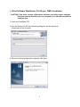
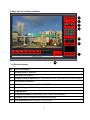
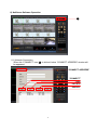
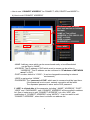
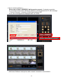
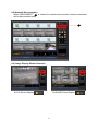
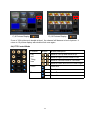
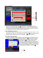
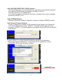
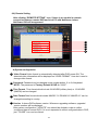
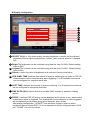
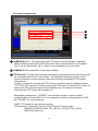
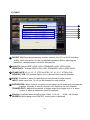
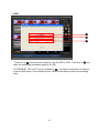
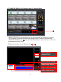
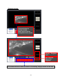
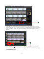
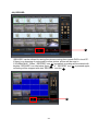
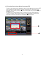
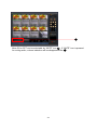
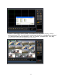
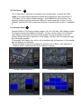
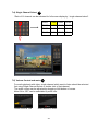
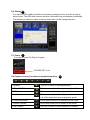
Client S/W User’s Manual (Model: 4/8/16CH MPEG-4 DVR) NetViewer Software File Player Software This user’s manual is subject to change without any previous notice by function upgrade or addition. Version_1.3 Feb, ‘2008 Table of Contents 1. Client Software Installation --------------------------------------------- Page 02 2. Client Software Operations 1) Client Software (NetViewer Software and File Player) --------------- Page 04 2) NetViewer Features -------------------------------------------------------------- Page 04 3) File Player Features ------------------------------------------------------------- Page 04 4) Main GUI of NetViewer Software -------------------------------------------- Page 05 5) Main GUI of File Player Software -------------------------------------------- Page 06 6) NetViewer Software Operation ----------------------------------------------- Page 07 6-1) Network Connection ---------------------------------------------------------- Page 07 6-2) Network Disconnection ------------------------------------------------------- Page 11 6-3) Image Display Widow Selection ------------------------------------------- Page 11 6-4) PTZ Control Mode ------------------------------------------------------------- Page 12 6-5) Local Setting -------------------------------------------------------------------- Page 13 6-6) Remote Setting ----------------------------------------------------------------- Page 15 6-7) REMOTE SEARCH ----------------------------------------------------------- Page 24 6-8) CAPTURE------------------------------------------------------------------------ Page 27 6-9) RECORD ------------------------------------------------------------------------ Page 29 6-10) MIC ON, Volume Control and Mute ------------------------------------- Page 30 6-11) Event Notification (Alarm, Motion) from remote DVR --------------- Page 31 7) File Player Software Operation ---------------------------------------------- Page 33 7-1) Folder Open -------------------------------------------------------------------- Page 33 7-2) File Open ------------------------------------------------------------------------ Page 35 7-3) Channel Select ----------------------------------------------------------------- Page 35 7-4) Single Channel Select -------------------------------------------------------- Page 36 7-5) Volume Control and mute --------------------------------------------------- Page 36 7-6) Setting ---------------------------------------------------------------------------- Page 37 7-7) Power ----------------------------------------------------------------------------- Page 37 7-8) Playback Icons (It is related to playback function) 7-9) Fast Playback ------------------------------------------------------------------ Page 38 7-10) Capture (SAVE, PRINT) ---------------------------------------------------- Page 39 7-11) File Conversion ( from MPEG4 to AVI) --------------------------------- Page 40 1 1. Client Software (NetViewer, File Player, CMS) Installation CAUTION: If an older version of Netviewer software or similar viewer software has been already installed on your computer, you should uninstall the software first. 1) Insert the installation CD. 2) Run the Setup.exe file. And following dialog box will be appeared. Please wait a few seconds. 3) When the following dialog box appears, click Next. 2 4) Please select installation style in following dialog box. “Complete” can selected for normal installation. And then click Next. 5) Please wait for a while. 6) Installation is finished. And Net_View, File_Player and CMS icon will be shown in PC as below picture. 2. Client Software Operations 1) Client Software Client Software consist of NetViewer, File Player and CMS. Net_Viewer S/W is Main client viewing S/W. Major function is Network Connection, Live Monitoring and network functions File Player is for file playback software. Its major function is each file playback and File conversion from MPEG-4 to AVI. * Requested PC System for Client Software - Operation System: MS Windows 2000, XP - CPU: Intel Pentium II 266MHz or higher - RAM: 64MB or Higher - VGA: AGP, Video RAM 8MB or Higher 2) NetViewer Features NetViewer Program support such as functions; Static, Dynamic IP and DDNS support Remote Live camera Monitoring Remote file searching, Backup, Playback PTZ camera control Remote Configuration and Firmware Upgrade Multi-user accessing support Full duplex two way audio transmission Event (Alarm, Motion) Notification 3) File Player Features Each file playback File conversion from MPEG-4 to AVI or JPEG 4 4) Main GUI of NetViewer Software 1 2 3 4 9 10 11 12 5 7 8 6 < ICON description > No. Icon Description 1 Network Connection and Disconnection 2 Display Channel Selection for Full screen, QUAD, 8 picture and 16 picture display 3 PTZ control for Pan, tilting, zooming and focusing 4 Local Setting for OSD display and saving directory. 5 Remote Setting for menu configuration 6 Program Exit 7 Audio Volume Control 8 Audio Mute ON/ OFF 9 Microphone ON/OFF for two way audio communication. 10 Recording in local PC. 11 Capture Start for single picture printing and saving. 12 Remote Searching 5 5) Main GUI of File Player Software 1 2 3 4 5 8 9 6 7 10 < ICON description > No. Icon Description 1 Folder Open for playback 2 File Open for playback 3 Display Channel Selection for Full screen, QUAD, 9 picture and 16 picture display 4 Full Screen Selection. 5 Audio Volume Control and Mute ON/ OFF 6 Local Setting for OSD setting 7 Program Exit 8 Playback buttons for normal play, Still/ Pause, Fast playback. 9 Capture Start for single picture printing and saving. 10 File Conversion from MPEG-4 to AVI format 6 6) NetViewer Software Operation 1 6-1) Network Connection When this “CONNECT” icon, 1 is clicked, below “CONNECT ADDRESS” window will be appeared. “CONNECT ADDRESS” “CONNECT” “ADD” “DELETE” “MODIFY” 7 < How to use “CONNECT ADDRESS” for CONNECT, ADD, DELETE and MODIFY > A) How to add “CONNECT ADDRESS” 1 Fill Group name, address, port, user and so on in blank. Example, NAME => Test_office1 ADDRESS => 192.168.123.101 PORT => 10000 USER => admin PASSWORD => 11111111 2 Click “ADD” - NAME: Arbitrary name which can be remembered easily or be differentiated can be filled in “NAME”. - ADDRESS: The IP address of DVR which want to access can be written in “ADDRESS”. This IP address can be confirmed in “IP address of NETWORK menu” in DVR. - PORT number: default is “10000”. ( It can be changeable according to network environment.) - USER is assigned as “ADMIN” . - PASSWORD: The “password of DVR” which want to access should be input here. If the password is not correct, network connection will be failed. The requested password is same as the DVR password. If “ADD” is clicked after all the parameter including “ NAME”, “ADDRESS”, “PORT”, “USER” and “ PASSWORD”, new “CONNECT ADDRESS” will be enrolled in address list. One of easier way to add “CONNECT ADDRESS” is to click “ADD” after modification of “CONNECT ADDRESS” using “MODIFY”. It can be useful to add “CONNECT ADDRESS”, when there is at least one address list. 8 B) How to delete “CONNECT ADDRESS” First, select one of listed “ADDRESS” which want to remove and then click “DELETE” to remove it. 2 Click “ DELETE” 1 Select “what want to delete” C) How to modify “CONNECT ADDRESS” First, select one of listed “ADDRESS” which want to modify and modify one of NAME, ADDRESS usually. Then click “MODIFY” to modify it. 1 2 9 Modify what want to modify. Click “ MODIFY” < How to connect network. > Select one of listed “ADDRESS”which want to connect. If network connection is succeeded, below initial “NetViewer Software” will be appeared in PC with message “ Connect Success” in bottom of NetViewer software GUI. If not, error message will be displayed after for a while. 2 Click “ CONNECT” 1 Select “what want to connect” < NetViewer Software initial picture after network connection is succeeded > 10 6-2) Network Disconnection When “DISCONNECT” 4 is clicked for network disconnection, network connection will be disconnected soon. 4 6-3) Image Display Widow Selection B) QUAD Picture Display A) Full Screen Display 11 C) 8 Pictures Display D) 16 Pictures Display If one of 16ch pictures is double-clicked, the channel will become to be full picture. It return to 16 picture display with double-click once again. 6-4) PTZ Control Mode Function Button Button Description Move to Left Up and move to Up. Pan and Tilting Icon Move to Right Up and move to Left. Move to Left and move to Left Down. Move to Down and move to Down Right Zoom Zoon Out Zoon In Focus Focus Far Focus Near 12 6-5) Local Setting 1 2 3 4 5 6 7 When the “LOCAL SETTING” icon, 5 of Main GUI is clicked, above sub-menu related to local setting will be appeared in main GUI. LOCAL SETTING consists of five parts which include OSD addition/ deletion, Motion-Alarm window pop-up, local recording path selection and remote firmware upgrade part. Part1: OSD addition/ deletion. OSD addition/ deletion is to add or delete the information of “channel number” , “time information” and “Font color” in each pictures. The “OK” of 6 can be clicked to save selection result. Unless it need to save, “CANCEL” of 6 can be pressed. Part2: Motion-Alarm Window If motion is detected or alarm is triggered in any channels of remote DVR under the condition that “Motion Window” and “Alarm Window” of 2 is selected, below subwindow will be appeared with motion or alarm information of 8 like “Motion-Event CH3 – 18:18:59”. The channel with motion detection or alarm triggering will be displayed as single picture, if “ VIEW” is clicked. If “CLOSE” is clicked, subWindow will be disappeared but event information will be displayed on bottom of GUI like 8 . 8 13 Part3: RECORD DIRECTORY (PATH) Selection This Record Directory is the recording directory path which is automatically assigned, when above RECORD button is clicked for recording in local PC. The default directory is C:\DVRBACKUP. If you want to change the directory for recording, recording directory can be changed by pressing “SELECT” icon. Part4: VERSION Dispaly Whenever NetViewer software is upgraded, it shows its software VERSION number. Part5: Remote Firmware Upgrade In order to upgrade the firmware of DVR remotely through network, the firmware file in PC can be searched by clicking “ SELECT”. And then firmware upgrade can be started by “UPDATE”. If firmware upgrade is succeeded, remote DVR can be rebooted automatically. If above “SELECT” is clicked, below file searching window will be appeared. After finding “upgrade software file”, new firmware will be upgraded by clicking “UPGRADE” icon through NetViewer software. “UPGRADE” icon 14 6-6) Remote Setting After clicking “REMOTE SETTING” icon, if there is no trouble in network connection between remote DVR and local PC with NetViewer, below NetViewer GUI will be appeared. 1 2 3 4 5 A) System configuration 1 Video Format Video format is automatically detected after DVR power ON. The detected video information will be displayed on VIDEO FORMAT. User don’t need to change video format. 2 Password Password can be changed using number button, 0 to 9 of keyboard. NOTE: The password of Factory Default in DVR is “1111”. 3 Time Format Time format which include 24 HOURS (military time) or 12 HOURS (AM/PM) can be changed. 4 Date Format Date format which include MM-DD-YY/ DD-MM-YY/ MM-DD-YY can be changed according to country. 5 Version It shows DVR software version. Whenever upgrading software, upgraded version number will be displayed. After system configuration, “UPDATE” icon should be clicked in order to reflect configured data in remote DVR. If it is not requested to reflect configured data in DVR, just “CLOSE” icon can be clicked. 15 B) Display configuration 1 2 3 4 5 6 7 8 1 SELECT CH All of 16ch video quality including brightness, contrast can be adjusted separately. Before adjusting brightness, contrast, video channel selection is needed first. 2 Bright The brightness can be controlled using slide bar from 1to 99%. Default setting value is 85%. 3 Contrast The contrast can be controlled using slide bar from 1to 99%. Default setting value is 80%. 4 Default It return the value of brightness and contrast to factory initial value. 5 SEQ. DWEL TIME It defines time interval of channel switching in live video or POP-UP mode related to motion detection and alarm triggering. 1 to 60 seconds time interval can be configured for sequence dwell time. 6 SPOT TIME It defines time interval of channel switching. 1 to 60 seconds time interval can be configured for sequence dwell time. 7 TIME DATE OSG It defines that time and date OSG is added or deleted in display picture. 8 POPUP It defines POP UP picture can be displayed as full screen or not, when motion is detected or alarm is triggered. The channel with motion detection or alarm triggered will be displayed as full screen during given seconds, about 30 sec. After display configuration, “UPDATE” icon should be clicked in order to reflect configured data in remote DVR. If it is not requested to reflect configured data in DVR, just “CLOSE” icon can be clicked. C) Camera configuration 1 2 3 1 CAMERA No. All of 16ch camera ID and PTZ protocol can be adjusted separately. Before selecting camera ID and PTZ protocol, video channel selection is requested first. It can be selected by “Up” or “Down” key of keyboard or mouse wheel. 2 CAMERA ID The camera ID can be easily modified. 3 PTZ Protocol The high end camera(s) with panning, tilting and zooming function would be connected with some of video inputs. The camera(s) has(have) its own control protocol needed to control panning, tilting and zooming, according to PTZ camera manufacturer. In order to control the camera with PTZ function in network viewer software remotely, PTZ TYPE (PTZ protocol) should be same with PTZ protocol of remote DVR. About 12 protocol for PTZ camera control can be available now. According to customer requirements, PTZ control will be added in it. After display configuration, “UPDATE” icon should be clicked in order to reflect configured data in remote DVR. If it is not requested to reflect configured data in DVR, just “CLOSE” icon can be clicked. * NOTE: PTZ stands for pan, tilt and zooming. * PTZ protocols: Panasonic/ Pelco-D/ Pelco/ PelcoP/ Techwin/ Niko/ DRX502A_DSC230s/ KRE_301_302/ GC_755_NP/ TOA_CC554/ RAS716LS and so on. 17 D) RECORD 1 2 3 4 5 6 7 1 Water Mark: DISABLE/ ENABLE. It is used for copy protection. 2 STOP KEY: DISABLE/ ENABLE. In case of manual recording, manual recording is started and stopped by the REC/ STOP button in the front panel of DVR. This REC/ STOP button ENABLE can protect the “recording stop” by unauthorized person intentionally. . It can be selected by “Up” or “Down” key of keyboard or mouse wheel. 3 SELECT CH, Resolution and RECORD Video channel from CH1 to CH16 which need recording can be selected separately. The video resolution for each channel can be selected separately from D1 (720x480), Half D1 (720x240) to CIF (352x240) in NTSC. After selecting channel in SELECT CH, recording can be selected as “DISABLE” or “ENABLE in RECORD with video resolution in Resolution. 4 QUALITY: VERY LOW, LOW, NORMAL, HIGH, VERY HIGH 5 FRAME RATE: 60, 30, 15, 10, 5, 1, 0.5 IPS.(NTSC) 6 AUDIO: ON/ OFF It defines whether audio signal with video together can be recorded or not. Recording of audio channel from CH1 to CH16 can be selected separately in 2) SELECT CH. The audio channel which don’t have to record can be selected as “OFF” after selecting channel in SELECT CH. 7 RECORD SCHEDULE “Weekly Schedule” recording or “Monthly Schedule” recording can be selected for schedule recording. If None is selected, there is no schedule recording. E) MOTION AREA 1 2 1 SELECT CH: In order to assign the area for motion detection, first video channel can be selected in 1 . Then area for motion detection can be selected using mouse like 2 . 19 F) EVENT 1 2 3 4 5 6 1 SELECT CH: Recording parameters of video channel from CH1 to CH16 including quality, frame rate and so on can be adjusted separately. Before adjusting the parameter, channel number should be selected first. 2 QUALITY 5 steps (VERY LOW, LOW, STANDARD, HIGH, VERY HIGH) SENSITIVITY: 5 steps (VERY LOW, LOW, STANDARD, HIGH, VERY HIGH) 3 FRAME RATE: 30, 15, 10, 5, 1FPS for NTSC. 25, 16, 10, 5, 1FPS for PAL SENSOR TYPE: N.O (Normal Open) or N.C (Normal Close) can be selected. 4 EVENT: Emotion or alarm for recording can be selected for each channel. INPUT: Alarm input from 1 to 16 can be selected for each channel. 5 PRE-RECORD: When event is occurred, pre-recording can be saved with recording file together. Normally, it store 5 seconds in D1 resolution for each channel. TRIGGER OUT It defines the selection of trigger output from trigger out1 to 4, when motion or alarm is detected in some of channels. 6 Duration: It defines alarm recording time. 30sec, 1,2,3,4,5, …,10,20,..,60 minutes. BUZZER It define beep sound ON/ OFF, when motion is detected. 20 G) WEEK SCHEDULE 1 2 3 4 5 6 Any day of a week from Monday to Sunday and any time of 24 hour can be reserved for WEEK SCHEDULE recording. Row of WEEK SCHEDULE 1 consist of 24 hours. Column of WEEK SCHEDULE 3 consist of SUN, MON, TUE and SAT. In the WEEK SCHEDULE, the schedule recording can be reserved separately. Event schedule recording will be started when event will be happened (motion detection or alarm triggering) within reserved time. Schedule recording by Record in red mark will be started in reserved time zone. NOTE: The recording reservation by event (motion or alarm) is represented as blue color box like 2 . The recording reservation for Record in red mark is represented as red color box like 4 . < How to setup “WEEK SCHEDULE” > 1. First, select one of recording condition in 5 among “None”, ”Record”, “Event”. 2. Time zone for schedule recording can be selected by mouse. 3. After doing WEEK SCHEDULE setting, “UPDATE” 6 should be clicked to update setting value to remote DVR. 21 H) MONTH SCHEDULE 1 2 3 4 5 6 Any day of a week from Monday to Sunday and any time of 24 hour can be reserved for MONTH SCHEDULE recording. Row of MONTH SCHEDULE 1 consist of 24 hours. Column of MONTH SCHEDULE 2 consist of Day1, Day2 and Day31. In the MONTH SCHEDULE, the schedule recording can be reserved separately. Event schedule recording will be started when event will be happened (motion detection or alarm triggering) within reserved time. Schedule recording by Record in red mark will be started in reserved time zone. NOTE: The recording reservation by event (motion or alarm) is represented as blue color box like 3 . The recording reservation for Record in red mark is represented as red color box like 4 . < How to setup “MONTH SCHEDULE” > 1. First, select one of recording condition in 5 among “None”, ”Record”, “Event”. 2. Time zone for schedule recording can be selected by mouse. 3. After doing MONTH SCHEDULE setting, “UPDATE” 6 should be clicked to update setting value to remote DVR. 22 I) HDD 1 2 3 “Total size” in 1 shows the total capacity of all the HDD in DVR. “Free size” in 2 is to show the remaining recordable capacity of HDD. “OVERWRITE” ON or OFF can be selected in 3 . It is used for repetitive recording in to same HDD space. First recorded area in HDD can be replaced with new recording data. 23 6-7) REMOTE SEARCH (for Playback and File downloading) 1 “REMOTE SEARCH” can be utilized for not only searching the files saved in remote DVR, playback of searched files but also doing backup of some of important files. “ REMOTE SEARCH” icon 1 of main GUI of NetViewer is clicked, below sub GUI will be appeared as below figure. Playback procedure can be followed from 2 to 6 . 6 5 Click “Play” for playback (PB). Select “minute” for PB. 4 Select “hour” for PB. 3 Select “channel” for PB. 2 24 Select “date” for PB. Playback picture. If mouse button is double-clicked, Small picture will be changed and vice versa. Display “Playback time”. Exit “RemoteSearch for Playback. * As another method to select the minute for recording, drag by mouse can be used. 25 File download (backup through backup) 5 Click “Download”. * When selecting the minute for download, drag by mouse can be used. Select “minute” for PB. 4 3 Select “hour” for PB. 2 Select “channel” for PB. 1 Select “date” for PB. The downloaded files which was save in C:\DVRBACKUP\20080209 directory can be played using “File Player”. 26 6-8) CAPTURE (Picture saving and Printing) 1 “CAPTURE” can be utilized for not only single picture saving but also picture printing. When “CAPTURE” icon is pressed, sub-GUI of “CAPTURE” will be appeared as below figure. “SAVE” or “PRINT” icon can be selected for either picture saving or picture printing. 2 3 When “SAVE” icon 2 is pressed, below sub-GUI of “SAVE” will be appeared and picture saving path will be requested as below figure. The file format for saving single picture is standard JPEG. 27 When “PRINT” icon 3 is pressed, below sub-GUI of “PRINT” will be appeared and picture printing path will be requested as below figure. The Selected picture will be printed. 28 6-9) RECORD 1 “RECORD” can be utilized for saving live picture coming from remote DVR in local PC. If there is no changing of saving path to save picture, picture will be save in C:\DVRBACKUP. When “ RECORD” icon 1 is pressed, recording will be started with brighter “RECORD” icon like below figure 2 . If “ RECORD” icon 2 is pressed again, recording will be stopped with dark “RECORD” icon like 1 . 2 29 6-10) MIC ON, Volume Control and Mute 1 2 For two way audio communication, the activation of microphone will be needed. “MIC ON” icon 1 can be pressed for “Microphone ON”. “MIC ON” icon will be turn into activation of “MIC ON” icon 3 . 3 For audio reproduction, single channel which want to listen audio should be selected first using Single Channel Select or double click of that channel. The audio volume can be adjusted by dragging of left button of mouse in 2 . 30 6-11) Event Notification (Alarm, Motion) from remote DVR If motion in any channel is(are) detected or alarm is (are) triggered in any remote DVR, event information will be noticed to NetViewer as below picture. NetViewer shows additional “Alarm/ Motion Window”, 4 with corresponding event information, 5 . As well as alert sound. If “VIEW” icon in “Alarm/ Motion Window” is clicked, full screen will be displayed. If “CLOSE” is clicked, “Alarm/ Motion Window” will be disappeared. But those event information is stored in Log data and is displayed in 5 continuously. 4 5 31 4 Mute ON or OFF can be selectable by “MUTE” icon 4 . If “MUTE” icon is pressed for muting audio, volume indication will be disappeared like 4 . 32 7) File Player Software Operation 1 2 3 4 5 6 7 8 7-1) Folder Open 9 10 11 1 This “Folder Open” icon is to select the directory or folder in local PC which live picture or back-up file through network has been saved for playback . If “Folder Open” icon is clicked, default directory, C:\DVRBACKUP will be shown. The directory related to backup media like USB or CD can be searched in there. For example, DVR or CD R/W drive is E:\. For file playback, searched folder (the folder which include all the recorded file capable of playback) can be selected. And it can playback by “play” button of No.8. 33 When “Folder Open” icon is clicked, C:\DVRBACKUP as default directory, will be shown as above GUI. Here the folder (or directory) which like to playback can selected. The selected folder can be opened by “OK” (or “Confirm”) as below GUI. The “play” button of No.8. can start the playback of the folder. 34 7-2) File Open 2 This “Folder Open” selection is to playback one recorded files. It means that File Open is for single channel playback included all of channels in one recorded file. If “File Open” icon is clicked, default directory, C:\DVRBACKUP will be shown. The directory related to backup media like USB or CD can be searched in there. For file playback, searched file can be selected. And then click play button of No.8. to playback it. 7-3) Channel Select 3 Channel Select of File Player program support 1ch, 4ch, 8ch and 16ch display window. For single channel video display or playback, 1ch icon can be clicked. For 8 channel video display or playback, 8ch icon can be clicked. For any 4ch display in the 4ch display, first picture can be selected in 16ch display. And then 4ch icon selection make any 4ch display possible. For example, 4ch display from ch5 to ch8 is possible after ch5 selection in 16ch display and 4ch display icon selection. Though File open for single file playback is selected, 4ch or 8ch or 16ch selection in “Channel Select” enable selected all the channel to display. < Single Channel Selection > < 4CH Channel Selection > < 8CH Channel Selection > < 16CH Channel Selection > 35 7-4) Single Channel Select 4 “Each of 16 channel can be selected for full screen display by “ single channel select”. CH01 CH02 CH03 CH04 CH05 CH06 CH07 CH08 CH09 CH10 CH11 CH12 CH13 CH14 CH15 CH16 7-5) Volume Control and mute 5 For audio playback with video, single channel which want to listen should be selected first using Single Channel Select or double click of that channel. The audio volume can be adjusted by dragging of left button of mouse. Mute ON or OFF can be selectable by mute icon. Audio sound is “ON” Audio sound is “Mute” 36 7-6) Setting 6 It is used for OSD addition/ Deletion and directory assignment for local file saving as below figure. The OSD with channel and time information can be separately controlled. The directory to save live video or backup video also can be changed by user. 7-7) Power 7 It is used to close File Player Program. “POWER OFF” icon 7-8) Playback Icons (It is related to playback function) 8 Playback : This icon is used for starting playback. STILL/ PAUSE This icon is used for still or pause playback file. STOP This icon is used for stopping playback. Fast Backward This icon is used for faster playback in backward. It is a little faster than normal playback speed. FRAME Backward One frame movement to backward in still mode. FRAME Forward One frame movement to forward in still mode. Fast Forward This icon is used for faster playback in forward. 7-9) Capture It is used for capturing single picture or printing it as below figure. Captured single picture is saved into JPEG file. < CAPTURE procedure > 1. Click “CAPTURE” icon. Then, this GUI will be appeared. 2. Click “SAVE” icon. Then, this GUI will be appeared for path assignment to save “CAPTURE” image. 3. Click “ Confirm” (or “OK”) 38 7-10) File Conversion ( from MPEG4 to AVI) The MPEG-4 file format recorded in HDD can be converted into AVI file format which can be playback using common software like Windows media player installed in most of PC. Conversion procedure will be followed below figure. If MPEG-4 to AVI file conversion is clicked, left figure will be appeared. First, select file path including MPEG-4 file which is needed to convert into AVI file. After assigning AVI input path, AVI output path can be assigned to other directory. Second, click “ Convert Raw MP4 to AVI” for conversion, after filling recording frame rate, image size in MP4 property. When MPEG-4 to AVI file conversion is finished, left figure will be appeared. Then please just click “OK”. 39 7-11) AVI file play The AVI file converted from MPEG.4 file can be played in common software like Windows media player installed in most of PC. Example of file selection for AVI playback Example of AVI file playback 40