1
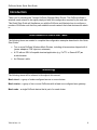
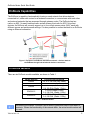
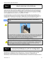
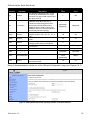
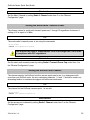
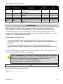
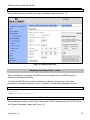
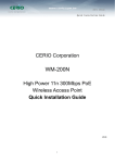
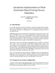
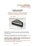
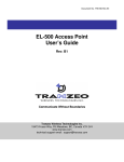
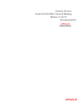
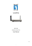
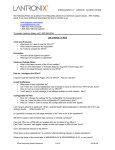
TR0154 Rev F1 EnRoute Series EN404/EN505/EN509/EN524-15/EN558-16 Quick Start Guide Applies to Firmware Version 5.5 Communicate Without Boundaries Tranzeo Wireless Technologies Inc. 19473 Fraser Way, Pitt Meadows, BC, Canada V3Y 2V4 www.tranzeo.com technical support email: [email protected] EnRoute Series Quick Start Guide Tranzeo, the Tranzeo logo and EnRoute are trademarks of Tranzeo Wireless Technologies Inc.. All rights reserved. All other company, brand, and product names are referenced for identification purposes only and may be trademarks that are the properties of their respective owners. Copyright © 2005-2011, Tranzeo Wireless Technologies Inc... TR0154 Rev. 5.5 2 EnRoute Series Quick Start Guide FCC Notice to Users and Operators This device complies with Part 15 of the FCC Rules. Operation is subject to the following two conditions: (1) This device may not cause harmful interference, and (2) This device must accept any interference received, including interference that may cause undesired operation. This equipment has been tested and found to comply with the limits for Class B Digital Device, pursuant to Part 15 of the FCC Rules. These limits are designed to provide reasonable protection against harmful interference in a residential installation. This equipment generates and can radiate radio frequency energy and, if not installed and used in accordance with the instructions, may cause harmful interference to radio communications. However, there is no guarantee that interference will not occur in a particular installation. If this equipment does cause harmful interference to radio or television reception, which can be determined by turning the equipment off and on, the user is encouraged to try to correct the interference by one or more of the following measures. Reorient or relocate the receiving antenna Increase the separation between the equipment and receiver Connect the equipment into an outlet on a circuit different from that to which the receiver is connected Consult the dealer or an experienced radio/TV technician for help Any changes or modification to said product not expressly approved by Tranzeo Wireless Technologies Inc. could void the user's authority to operate this device. The Tranzeo EnRoute Mesh Router must be installed by a trained professional, value added reseller, or systems integrator who is familiar with RF cell planning issues and the regulatory limits defined by the FCC for RF exposure, specifically those limits outlined in sections 1.1307. TR0154 Rev. 5.5 3 EnRoute Series Quick Start Guide Introduction Thank you for choosing the Tranzeo EnRoute Wireless Mesh Router. The EnRoute allows a wireless mesh network to be rapidly deployed with little configuration required by the end user. This Quick Start Guide will familiarize you with the EnRoute and illustrate how to configure a number of EnRoute such that they can establish a mesh network that client devices can attach to. Items Needed For Quick Start Tasks The following items are needed to complete the configuration examples described in this Quick Start Guide: Two or more EnRoute Wireless Mesh Routers, including all accessories shipped with it (power adapters, POE injectors, antennas) A PC with an SSH v2-capable terminal application (e.g. PuTTY or SecureCRT) or a web browser An Ethernet cable Terminology The following terms will be referred to throughout this manual. Mesh cloud – a group of nodes configured as one or more clusters Mesh cluster – a group of two or more EnRoutes with at least one configured as a gateway Mesh node – a single EnRoute device that is part of a mesh cluster TR0154 Rev. 5.5 4 EnRoute Series Quick Start Guide EnRoute Capabilities The EnRoute is capable of automatically forming a mesh network that allows devices connected to it, either with a wired or a wireless connection, to communicate with each other and external networks that are accessed through gateway nodes. The EnRoute has two radios, an 802.11a mesh backhaul radio and an access point radio for 802.11b/g-client devices. An EnRoute will currently support up to four virtual access points (APs), each with different access and performance settings. It is also possible to connect devices to an EnRoute using an Ethernet connection. Figure 1. Example of an EnRoute stand-alone network – devices attach to the EnRoute through both wired and wireless connections EnRoute Models There are six EnRoute models available, as shown in Table 1. Model Number EN404 EN505 EN509 EN524-15 EN558-16 Frequencies Supported 2.4, 4.9, 5.8 GHz (Any Radio) 2.4, 5.8 GHz (Any Radio) 900 MHz (Radio 0 Only) 2.4, 5.8 GHz (Radio 1 Only) 2.4 GHz (Radio 0 Only) 2.4, 5.8 GHz (Radio 1 Only) 5.8 GHz (Radio 0 Only) 2.4, 5.8 GHz (Radio 1 Only) Table 1. EnRoute Models Throughout the manual, “EnRoute” will be used to collectively refer to this family of products. Where the functionality of the variants differ, the actual model number will be used. TR0154 Rev. 5.5 5 EnRoute Series Quick Start Guide EnRoute Interfaces The interfaces available on the EnRoute are Ethernet and two radio ports. Radio 0 Antenna Port Radio 1 Antenna Port Default: MESH Default: ACCESS POINT 10/100Base-T Ethernet Figure 2. EnRoute interfaces (EN505 shown) Interface Radio 0 Port Radio 1 Port Ethernet Port with Passive PoE Description N-type antenna connector for Radio 0, which is associated with the for mesh interface by default N-type antenna connector for Radio 1, which is associated with the access point interface by default 10/100Base-T Ethernet interface (RJ-45) with Passive PoE Support Not compatible with IEEE 802.3af. See the EnRoute User’s Guide for more information on the PoE operation. The EN524-15 and EN558-16 are equipped with an integrated panel antenna for the access point, so only one antenna connector for the mesh interface is available on these two models. TR0154 Rev. 5.5 6 EnRoute Series Quick Start Guide Quick Start Guide Configuration Overview This quick start will walk you through how to configure a basic network using two or more EnRoutes. The guide shows how to: 1. Configure a mesh to have either an Internet extension or stand-alone network topology 2. Give each node a unique ID 3. Assign 802.11 channels used for mesh and AP communication 4. Set a custom WEP encryption key for one of the EnRoute’s APs 5. Configure an EnRoute gateway that will be connected to an external network The EnRoute User’s Guide provides a more comprehensive overview of all of the EnRoute features, many of which are not described in this Quick Start Guide. An EnRoute can be configured using a command-line interface (CLI) or a browser-based graphical user interface (GUI). Instructions for configuring the EnRoute using either interface are provided throughout the Quick Start Guide. TR0154 Rev. 5.5 7 EnRoute Series Quick Start Guide Step 1 Attach antennas to the EnRoute Using the right-angle connectors, attach the supplied antennas to the mesh and access point (AP) radio ports on the back of the EnRoute radio. All of the EnRoute products are shipped with two omni directional antennas. The bigger diameter antenna is for operation at 2.4GHz, and the smaller diameter antenna is for operation at 5.8GHz. It is important that you correctly match the antennas with the radio ports according to the frequency allocation plan for your network. Please refer to the User’s Manual for deployment considerations. The location of the mesh and AP antenna ports are shown in Figure 2. Only the mesh antenna needs to be attached on the EN524-15 and EN558-16 models. It is important that you tighten the N-type connections on both ends of the right-angle connectors. Also, ensure that the antennas are pointed in the desired direction(s), and are tightly wrapped with self-sealing weatherproof tape for maximum environmental protection and to prevent unintended movement. Radio 0 and Radio 1 antenna ports are labeled MESH and ACCESS POINT, espectively, for your convenience to correspond to default settings. These settings can be changed via the web or CLI interfaces, in which case these labels may become irrelevant and should be changed accordingly. Step 2 Connect the EnRoute to a PC for Configuration An EnRoute is configured through its Ethernet port. Connect an Ethernet cable from the Ethernet port of the EnRoute to the computer that you will use to configure the unit. Alternatively, connect the EnRoute to an Ethernet network connected to the computer used for TR0154 Rev. 5.5 8 EnRoute Series Quick Start Guide configuration. The parameters for the EnRoute’s configuration Ethernet interface are listed in Table 2. The EnRoute is equipped with an auto-sensing Ethernet port that allows both regular and cross-over cables to be used to connect to it. Since the configuration IP address (shown in Table 2) is the same for all EnRoutes, you should not simultaneously connect multiple EnRoutes to a common LAN and attempt to access them using the configuration IP address. Parameter IP address Netmask Setting 169.254.253.253 255.255.0.0 Table 2. EnRoute Ethernet configuration interface settings The computer that you are using to configure the EnRoute needs to have an IP address on the same subnet as the EnRoute. The steps below describe how to set the IP address in Windows XP. 1. Open the “Control Panel” 2. Select “Network and Internet Connections” and then “Network Connections when using the Category View for the Control Panel or “Network Connections” when using the Classic View. 3. Double-click the connection you plan on using to connect to the EnRoute. 4. Click on the “Properties” button 5. Select “Internet Protocol (TCP/IP)” and click on “Properties”. TR0154 Rev. 5.5 9 EnRoute Series Quick Start Guide 6. Select “Use the following IP address”, enter 169.254.253.1 as the IP address, set the subnet mask to 255.255.0.0, and then click on “OK”. 7. Click on “Close” to close the network connection properties window and click on “Close” to close the network connection status window. Aliased IP Address If you want to configure a network interface in Windows XP to have multiple IP addresses, follow the first five steps in the procedure above and then carry out the following steps. TR0154 Rev. 5.5 10 EnRoute Series Quick Start Guide Assigning multiple IP addresses to a network interface allows you to use a single physical network interface to communicate directly with devices on multiple subnets. For example, the EnRoute can be on one subnet while the other devices on the LAN are on a different subnet. 1. Select “Use the following IP address”, then enter the IP address and subnet that you want to use for communicating with devices other than the EnRoute. 2. Click on “Advanced…” 3. Click on the “Add…” button in the “IP addresses” box. TR0154 Rev. 5.5 11 EnRoute Series Quick Start Guide 4. Enter 169.254.253.1 as the IP address and 255.255.0.0 as the subnet. This will be the address that is used to communicate with the EnRoute. Click on “OK”. 5. Click on “OK” to close the “Advanced TCP/IP Settings” window, click on “Close” to close the network connection properties window, and click on “Close” to close the network connection status window. Windows XP does not include an SSH client application. You will need to install a 3rd-party client such as SecureCRT from Van Dyke software (http://www.vandyke.com/products/securecrt) or the free PuTTY SSH client (http://www.putty.nl/) to connect to an EnRoute using SSH. TR0154 Rev. 5.5 12 EnRoute Series Quick Start Guide Step 3 Power up the EnRoute and log in Connect the EnRoute radio to the CPE port of the supplied POE injector using a normal Ethernet cable. Connect the power plug of the supplied DC adapter into the power jack of the POE injector, then plug the adapter into an AC outlet. The EnRoute radio will automatically power up. The boot process takes approximately 75-90 seconds. Parameter IP address User name Default password Setting 169.254.253.253 admin default Table 3. EnRoute login parameters Connect an Ethernet cable between the PC port of the POE Injector and your computer. The EnRoute is equipped with an auto-sensing Ethernet port that allows both regular and cross-over cables to be used to connect to it. CLI Log in to the EnRoute using an SSH v2 client. The IP address, username, and default password are listed in Table 3. The EnRoute only supports SSH v2, and not SSH v1. Web Interface Open a browser and enter the URL “https://169.254.253.253”. You will receive a warning about the site’s certificate. This warning can safely be ignored. Enter the username and password listed in Table 3 when prompted to login. Figure 3. Web interface login TR0154 Rev. 5.5 13 EnRoute Series Quick Start Guide Step 4 Configure the EnRoute All initial configuration of the EnRoute is done with Tranzeo’s command line interface (CLI) or web interface. Descriptions for setting parameters are provided for both configuration approaches. CLI Overview The structure of the CLI resembles the user interface commonly used for routers. Please note that after changing a setting with the CLI you will have to apply the changes for the setting to take effect. Note that some settings will trigger a reboot of the EnRoute while others will be applied on the fly. The CLI presents you with a prompt, which indicates the currently selected interface. By default no interface is selected when you log in. Last login: Mon Feb 20 23:11:57 2006 from 169.254.253.1 Shell timeout: 360 minutes. Press '?' for help.. > Figure 4. Prompt after login Below we will configure several parameters for different interfaces. Thus it is important to ensure that you have the correct interface selected when setting a parameter. To select an interface, use the command use <interface name> In this document a ‘use’ command is always shown prior to a ‘set’ or ‘get’ command to avoid the possibility of applying a setting to the wrong interface. It is not necessary to enter the ‘use’ command if your prompt indicates that you already have selected the correct interface. At any time you can get help information about the CLI by pressing ‘?’. Web Interface Overview The web interface can be navigated by using the menu on the left side of the screen and the tabs and sub-tabs that are presented at the top of certain pages. Many of the web interface pages allow you to set the EnRoute’s operating parameters. Each page that contains settable parameters has a “Save Changes” button at the bottom of the TR0154 Rev. 5.5 14 EnRoute Series Quick Start Guide page. When you have made your changes on a page and are ready to commit the new configuration, click on the “Save Changes” button. It typically takes a few seconds to save the changes, after which the page will be reloaded. For the changes to take effect, they must be applied. After one or more changes have been saved, a message reminding the user to apply these changes will be displayed at the top of the screen. Figure 5. Sample page showing "Save Changes" button and message prompting the user to reboot Parameters to Set An overview of the parameters that should be set for a minimal EnRoute configuration is provided in the table below. After familiarizing yourself with the parameters, proceed to set them as described in the section following the table. Interface Sys Parameter id.node TR0154 Rev. 5.5 Description The unique identifier for the node in the mesh cluster. This value will be the last octet in the node’s mesh IP address. It can be set to any value from 1 to 254. All EnRoutes in a given mesh cluster require a unique sys.id.node value to identify them. Suggested value Default value any value in the range from 1 to 254 253 15 EnRoute Series Quick Start Guide Interface Parameter Sys id.mesh sys sys.scheme wlan0 channel wlan0 txpower wlan1 channel wlan1 essid wlan1 wpa.enable wpa.key_mgmt wlan1 wlan1 wlan1 wpa.passphrase txpower Description An identifier in the range from 1 to 254 that uniquely identifies a mesh cluster. All nodes in a given cluster need to have the same mesh ID The EnRoute’s operating mode. Repeater mode allows devices to connect to it both through the built-in access point and the Ethernet port. Gateway mode is used to connect an EnRoute radio to an external network in an Internet extension topology. The 802.11a channel used for the mesh network (must be 149, 153, 157, 161, or 165) Sets the transmit power for the mesh radio The 802.11b/g channel used by the internal access points in an EnRoute The ESSID for the EnRoute’s ‘wlan1’ access point Controls whether WPA is enabled or not Controls what form of WPA is used Sets WPA PSK value Sets the transmit power for the ‘wlan1’ access point radio Suggested value Default value 1 253 aprepeater/ apgateway aprepeater 149 149 30 30 6 1 EnRoute_ap1 EnRoute_ap1 yes No WPA-PSK WPA-PSK N/A (pick a unique passphrase) <blank> 30 30 Many of these parameters can be set via the “Minimal Configuration” page (see Figures 6 & 7) Figure 6. Setting Admin Password, operating scheme, and radio channels TR0154 Rev. 5.5 16 EnRoute Series Quick Start Guide Figure 7. Setting Transmit power, DNS server, Node ID, Mesh ID, Mesh ESSID, and AES key Restoring Factory Settings Load the FACTORY profile to restore defaults settings via the “Load” tab on the “Profile Management” page (Figure 8). Figure 8. Loading Factory Profile TR0154 Rev. 5.5 17 EnRoute Series Quick Start Guide Set the Operating Scheme The operating scheme determines a node’s role in the mesh network. Typically one of two configurations will be used in a network: All EnRoutes will be configured as repeater nodes to create a stand-alone mesh cluster. At least one of the EnRoutes in a mesh cluster will be configured as a gateway node, with the remaining nodes configured as gateways or repeaters. The gateway nodes are connected to an external network using the nodes’ Ethernet interfaces. This network configuration will create an Internet extension network. Mode repeater gateway Description The EnRoute will function as a relay in the mesh network. Client devices can connect to the node using both wired (10/100 Ethernet) and wireless (built-in APs) interfaces. The node can provide IP addresses to clients on both the wired and wireless interfaces. The EnRoute will function as a relay in the mesh network and a gateway to a WAN using the Ethernet interface for backhaul communication. Client devices can only connect to the node using only the wireless (built-in APs) interfaces. The node can provide IP addresses to clients on the wireless interface. Ethernet interface Client devices can connect to it. IP addresses can be provided to client devices using DHCP or be manually configured. Used to connect the mesh cluster to a larger network. Will expect to be provided an IP address by a DHCP server or have a static address assigned to it. Table 4. EnRoute operating schemes The Internet extension network topology example described in this Quick Start Guide has one ‘apgateway’ per mesh cluster. Ensure that only one node in the network is configured as an ‘apgateway’. CLI To set the EnRoute’s Operating Scheme, use the commands > use sys sys> set scheme=<operating scheme> For example, to set the operating scheme ‘apgateway’ mode use: > use sys sys> set scheme=apgateway Web Interface The Operating Scheme is Item 2 on the “Minimal Configuration” page. TR0154 Rev. 5.5 18 EnRoute Series Quick Start Guide Set the Node ID The node ID identifies a node in a mesh cluster and each node in a mesh cluster must be assigned a unique Node ID value. The allowable range for node IDs is 1 through 254. CLI Set the node ID with > use sys sys> set id.node=<node ID> Web Interface The Node ID is part of Item 6 on the “Minimal Configuration” page. Set the Mesh ID The mesh ID identifies a mesh cluster. Each member of a mesh cluster must be assigned the same mesh ID. In order to support multiple different meshes in a single location, each mesh must have a unique mesh ID. The allowable range for mesh IDs is 1 through 254. CLI Set the Mesh ID with > use sys sys> set id.mesh=<mesh ID> Web Interface The Mesh ID is part of Item 6 on the “Minimal Configuration” page. Setting the Mesh Channel All the nodes in a mesh need to be configured to use the same 802.11a channel. Valid values for a 20MHz channel setting are 149, 153, 157, 161, and 165. All of these channels are nonoverlapping and reside in the 5.7-5.8 GHz ISM band. CLI Set the channel used for the mesh with > use wlan0 wlan0> set channel=<channel #> TR0154 Rev. 5.5 19 EnRoute Series Quick Start Guide Web Interface Set the Mesh Channel by setting Radio 0 Channel under Item 3 on the “Minimal Configuration” page. Setting the Mesh Radio Transmit Power The allowed values for mesh radio transmit power are 1 through 30 regardless of channel. A setting of 60 is equal to 24 dBm. CLI The mesh radio’s transmit power is set using the commands > use wlan0 wlan0> set txpower=<tx power> You must set the value of ‘wlan0.txpower’ to be in the range from 1 to 60 to be in compliance with FCC regulations. Web Interface Set the mesh radio transmit power by setting Radio 0 Transmit Power Cap under Item 4 on the ”Minimal Configuration” page. Setting the Access Point Channel The channel used by the EnRoute’s built-in access points can be set. In a deployment with more than one EnRoute radio, the non-overlapping channels 1, 6 and 11 should be used in an alternating fashion to maximize throughput and minimize interference. CLI The channel for the EnRoute’s access point 1 is set with > use wlan1 wlan1> set channel=<channel #> Web Interface Set the access point channel by setting Radio 1 Channel under Item 3 on the “Minimal Configuration” page. TR0154 Rev. 5.5 20 EnRoute Series Quick Start Guide Setting the Access Point Radio Transmit Power The maximum allowed value for ‘txpower’ depends on the access point channel that has been selected, as shown in Table 5. The minimum allowed value is 1. Channel 1 2 – 10 11 Tx Power (dBm) 20 dBm 28 dBm 20 dBm txpower setting 10 25 10 Table 5. Access point transmit power limits CLI The access point radio’s transmit power is set using the commands > use wlan1 wlan1> set txpower=<tx power> You must set the value for ‘wlan1.txpower’ to be in the ranges shown in Table 5 to be in compliance with FCC regulations Web Interface Set the access point radio transmit power by setting Radio 1 Transmit Power Cap under Item 4 on the ”Minimal Configuration” page. Setting the Mesh ESSID Set the ‘wlan0’ mesh interface ESSID to a common value for all nodes in a mesh cluster. It should be different than the ESSID for any adjacent mesh clusters. By default the ‘wlan0’ ESSID is set to ‘newMesh’ The SSID value must be a text string that has a maximum length of 32 characters. It must only contain alphanumeric characters, spaces, dashes (“-“), and underscores (“_”). The SSID setting is case sensitive. CLI The ESSID for the EnRoute’s ‘wlan0’ mesh interface is set with > use wlan0 Wlan0> set essid=<essid name> Web Interface The Mesh ESSID is Item 7 on the “Minimal Configuration” page. TR0154 Rev. 5.5 21 EnRoute Series Quick Start Guide Setting the AES Encryption Key for the Mesh Change the default AES encryption key to prevent unauthorized access to the mesh. The mesh encryption key must be the same for all nodes in a mesh cluster. The mesh “AES key” can either be specified as a 16-character ASCII string preceded by “s:” or a 32-character hexadecimal string. CLI The mesh AES key for the EnRoute’s ‘wlan1’ access point is set with > use wlan0 Wlan0> set key=”s:<ASCII key> or using a hexadecimal key with > use wlan0 Wlan0> set key=”<HEX key> Encryption can be disabled by specifying a blank value as shown below. > use wlan0 wlan0> set key= Web Interface The Mesh Key is Item 8 on the “Minimal Configuration” page. Setting the Access Point ESSID You can assign a common access point ESSID to all the EnRoute’s in your network or you can set ESSIDs to be unique for each EnRoute to enable client connections to specific mesh nodes. By default the ‘wlan1’ ESSID is set to ‘er500ap_default1’ The ESSID name can contain only alphanumeric characters and the characters ‘_’ and ‘-‘. The maximum allowed length for an ESSID is 32 characters. CLI The ESSID for the EnRoute’s ‘wlan1’ access point is set with > use wlan1 wlan1> set essid=<essid name> Web Interface Set the ‘wlan1’ access point ESSID via the “wlan1” tab on the “Interfaces” page (see Figure 9). TR0154 Rev. 5.5 22 EnRoute Series Quick Start Guide Figure 9. Setting the ‘wlan1’ access point ESSID Setting the Access Point Encryption Key By default, the access point has a WEP encryption key set that clients must use in order to connect. It is recommended that WPA encryption is enabled instead of WEP. The minimum number of characters required for the WPA passphrase is 8. However, it is recommended that a longer passphrase, on the order of 15-20 characters, is used to increase the strength of the encryption used for the wireless link. It is possible to set different encryption keys for APs on different EnRoutes. However, if this is done, it will not be possible for client devices to seamlessly connect to any of the EnRoutes using the same AP ESSID in a network since they use different encryption keys. TR0154 Rev. 5.5 23 EnRoute Series Quick Start Guide CLI The example below shows how to enable WPA-PSK encryption for WLAN1. > use wlan1 wlan1> set wpa.enable=yes wlan1> set wpa.key_mgmt=”WPA-PSK” wlan1> set wpa.passphrase=<your passphrase> Web Interface Set the access point encryption key via the “WPA/WEP” sub-tab under the “AAA” tab on the “System Parameters” page (see Figure 10). Select ‘WPA-PSK” from the drop-down menu for WLAN1 and enter a passphrase in the edit box below the drop-down menu. Figure 10. Setting ‘wlan1’ encryption settings Gateway Parameters If you have configured a node as a gateway (sys.scheme set to ‘apgateway’), you may need to change the settings for the parameters listed in the table below, depending on the network to which you are connecting the gateway. It is not necessary to set these variables for repeater nodes. Interface sys Parameter nat.enable TR0154 Rev. 5.5 Description Controls whether NAT is enabled or disabled. Suggested value Default value yes no 24 EnRoute Series Quick Start Guide Interface Parameter eth0 dhcp eth0 ip.address_force eth0 ip.broadcast_force eth0 eth0 ip.netmask_force ip.gateway_force firewall enable Description Controls whether the gateway will attempt to acquire an address via DHCP or use a static address IP address for the Ethernet interface Broadcast address for the Ethernet interface Netmask for the Ethernet interface Gateway for the Ethernet interface Controls the state of the EnRoute’s firewall Suggested value Default value client none N/A 10.253.253.225 N/A 10.253.253.255 N/A N/A 255.255.255.224 <blank> yes yes Enabling NAT Network Address Translation (NAT) isolates your mesh cluster from the network that the cluster gateway is connected to through its Ethernet port. The mesh nodes and their client devices are able to communicate with devices connected to the external network, however, devices on the external network cannot initiate communication with any mesh nodes, or clients of mesh nodes, other than the mesh gateway. The advantages of using NAT are: You can easily attach a mesh to an existing network. You do not need to modify any settings on the router on your existing network to forward packets to the addresses used in your mesh. The mesh nodes are shielded from the network that the gateway is attached to. You only consume a single IP address on your existing network when connecting the mesh to it. The main disadvantage of using NAT is that you are not able to initiate connections with mesh nodes or their clients from outside the mesh network If you do not enable NAT, you will have to configure the router on the LAN segment that the mesh cluster gateway is connected to to forward all traffic for the following subnets to IP address of the mesh cluster gateway’s Ethernet interface: <sys.id.lanprefix>.<sys.id.mesh>.0.0/255.255.0.0 <sys.id.mesh_prefix>.<sys.id.mesh>.0/255.255.255.0 CLI To set the NAT state, use the commands > use sys sys> set nat.enable=<yes|no> TR0154 Rev. 5.5 25 EnRoute Series Quick Start Guide Web Interface Set the NAT state via the “eth0” tab on the “Interfaces” page (see Figure 11). Figure 11. Setting the NAT state Gateway: Ethernet DHCP Client When configured as a gateway, the EnRoute can be configured to use DHCP to get an address for its Ethernet interface. To enable the DHCP client mode for the Ethernet interface, set the value of the ‘dhcp’ parameter in the ‘eth0’ interface to ‘client. To disable it, set the ‘dhcp’ parameter to ‘none’. CLI > use eth0 eth0> set dhcp=<client|none> Web Interface Set the backhaul interface DHCP client state on the “DHCP” sub-tab under the “DHCP” tab on the “System Parameters” page (see Figure 12). TR0154 Rev. 5.5 26 EnRoute Series Quick Start Guide Figure 12. Setting the backhaul DHCP configuration Gateway: Manually Configuring the Ethernet Interface If you have disabled DHCP for the Ethernet interface, you will need to manually configure the interface. TR0154 Rev. 5.5 27 EnRoute Series Quick Start Guide If you have configured the Ethernet interface to be a DHCP client, any settings you manually configure will be overridden when the EnRoute has received an address and other configuration information from a DHCP server. The settings that need to be entered are the IP address, the broadcast address, the netmask, and, optionally, a gateway for the interface. CLI These IP address-related parameters are set using the following commands: > use eth0> eth0> eth0> eth0> eth0 set ip.address_force=<your.ip.address.here> set ip.netmask_force=<your.net.netmask.here> set ip.broadcast_force=<your.broadcast.address.here> set ip.gateway_force=<your.gateway.address.here> Web Interface Set the IP parameters for the wired/backhaul Interface via the “eth0” tab on the “Interfaces” page (see Figure 13). Figure 13. Setting backhaul interface IP settings TR0154 Rev. 5.5 28 EnRoute Series Quick Start Guide Setting the Firewall State An EnRoute has a firewall that can be enabled or disabled. The firewall blocks communication based on a variety of parameters that can be configured with the CLI. The default settings are typically sufficient to allow most types of common communication. It is only suggested that you disable the firewall if you are encountering problems with establishing communication between your mesh and external devices. If you have enabled NAT, you will have an implicit firewall that limits the type of inbound connections that are possible. CLI The commands for controlling the state of the firewall are: > use firewall firewall> set enable=<yes|no> Web Interface It is not currently possible to set the firewall state via the web interface. Optional Parameters The parameters in the following table are optional to change. You can keep the default factory settings for these parameters, or configure them to conform to your network management framework. Be sure to set the interface using prior to setting these parameters. use <interface name> Interface Parameter wlan0 essid sys id.lanprefix sys id.meshprefix sys shell.timeout TR0154 Rev. 5.5 Description The ESSID used by the EnRoute for the mesh. This needs to be set to be the same for all EnRoute devices in a given mesh. The first octet of the local subnet for devices connected to an EnRoute The first two octets of the mesh IP addresses. It is recommended that this value is in the range from 172.16 to 172.29. The CLI will automatically log out a user after a specified time of inactivity. This setting allows you to specify, in minutes, how long this timeout value is. Suggested value Default value newMesh newMesh 10 10 172.16 – 172.29 172.29 20 20 29 EnRoute Series Quick Start Guide Verifying Parameters CLI You can use the following commands to verify parameter settings. Select an interface with use <interface> and then retrieve a parameter setting with get <parameter name> For example, to retrieve a node’s ID, use the commands > use sys sys> get id.node The ‘*” character can be used to specify wildcard characters. The example below illustrates how all the parameters in the ‘sys’ interface that start with ‘id.’ can be retrieved. > use sys sys> get id.* This command will return: sys.id.lanprefix = 10 sys.id.mesh = 4 sys.id.meshprefix = 172.29 sys.id.node = 7 TR0154 Rev. 5.5 30 EnRoute Series Quick Start Guide Web Interface Configuration values can be verified by bringing up the page on which they were set. Many current operating parameters are available on the web interface “Status” page (Figure 14). Figure 14. Sample status page TR0154 Rev. 5.5 31 EnRoute Series Quick Start Guide Step 5 Reboot the EnRoute Reboot the EnRoute either by removing power and reapplying it, issuing the CLI command reboot at a CLI command prompt, or clicking on the “Reboot now” button on the “Reboot” page in the web interface (Figure 15). Figure 15. Rebooting the node By rebooting the node, the configuration changes that have been made will take effect. Step 6 Configure other EnRoutes to be used in the network Repeat steps 1 through 5 for all the EnRoutes to be used in the network. Remember to assign unique node ID (sys.id.node) values to all EnRoutes used in the network. If you are setting up a Internet extension network, remember to set one node to be an ‘apgateway’ by configuring its sys.scheme parameter appropriately. TR0154 Rev. 5.5 32 EnRoute Series Quick Start Guide Using Victor to Locate and Change IP Address of EnRoute Radios The Tranzeo Victor Program is a utility that allows users to quickly locate and change the IP address of Tranzeo radios. It sends out a broadcast on the network and displays a list of other Tranzeo radios connected, from which you can configure the IP address for your device. Figure 16. Victor’s Scan Results Screen You can display the EnRoute information by highlighting a device, and selecting Details from the Run menu. Figure 17. Victor’s Mesh Details Screen You can change the IP address and subnet of the Configuration Interface: Figure 18. Victor’s IP Address Change Screen You can download the latest version of Victor from the Tranzeo Support Website. TR0154 Rev. 5.5 33 EnRoute Quick Start Guide Enabling Victor Access Victor Scans is enabled by default in the EnRoute radios. You may disable Victor access via the Victor tab on the “System Services” page (Figure 19). Figure 19. Configuring Victor’s Access TR0154 Rev. 5.5 34