1
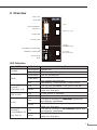
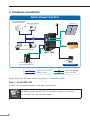
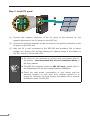
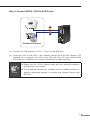
Industrial Solar Power PoE Switch
BSP-300
Quick Installation Guide
Safety Precautions
Please read before using
1.All electrical work must be done in accordance with local, and/or international
electrical codes.
2.Before installing or using this device, read all instructions and cautionary marking
located in (or on) this guide, the controller, the batteries, PV (Photovoltaic) array
and any other device used.
3.To reduce the risk of short-circuits, use insulated tools when installing or working
with the inverter, the controller, the batteries, or any DC source (e.g., PV).
4.Remove all jewelry. This will greatly reduce the chance of accidental exposure to
live circuits.
6.The controller contains more than one live circuit (batteries and PV array). Power
may be present at more than one source.
7.This product contains no user serviceable parts. Do not attempt to repair this
unit unless fully qualified.
Table of Contents
1. Package Contents........................................................................................ 4
2. Overview.................................................................................................... 5
3. Hardware Installation................................................................................... 6
Further Information.........................................................................................11
1.Package Contents
ll 1 x BSP-300
ll 1 x Quick Installation Guide
ll 1 x RS232 Console Cable
ll 1 x CD
ll 2 x Rack Ear
ll 1 x Screw Kit
4
2.Overview
System LED
FAULT LED
FAULT
SYSTEM
+
PV In
1
-
10/100/1000Base-T
PoE port x 2
PV In
+
2
Battery In / Out
-
Link/ACT LED
1
Bat. In/Out
2
Link/ACT
PoE In Use
PoE in Use LED
10/100/
1000Base-T port
3
10/100Base-TX Link/ACT LED
Link/ACT
1000
RJ-45 type
RS-232 Console
1000Base-T Link/ACT LED
DO
GND
4-Pin Terminal
Block
RS-232
GND
+24V
BSP-300
LED Definition
LED
System
Fault
Link/ACT
(For Port 1~2)
PoE in Use
Status
System On.
Fast Blink
The battery is Charging.
Slow Blink
The PV disconnects.
Fast Blink
The battery voltage is less than the value for
low-voltage disconnection.
On
Bad Battery / Over-current / Short-circuit.
On
The 10/100/1000Base-T PoE port is link up.
Blink
The BSP-300 is actively sending or receiving
data over that port.
On
A PoE device is detected.
Off
No PoE device attached.
On
1000
Blink
Link/ACT
(10/100Base-TX
For Port 3)
Description
Slow Blink
On
Blink
The port is running in 1000Mbps speed and
successfully established.
The BSP-300 is actively sending or receiving
data over that port.
The port is running in 10/100Mbps speed and
successfully established.
The BSP-300 is actively sending or receiving
data over that port.
5
3.Hardware Installation
Solar Power System
Long-range Wireless
Backhaul/Bridge
Wireless CPE/AP
Solar PV
OR
DC
PoE
PoE
DC
OR
Battery
Outdoor IP Camera
DC
BSP-300
|O|O|
Laptop
Ethernet Extender/
DC Powered Device
PoE
Local Console
1000Base-T UTP with PoE
1000Base-T UTP
|O|O|
DC
Serial Line (RS-XXX)
Power Line (DC)
Please follow the following steps (sequence) to install the system:
Step 1.Install BSP-300
Fix BSP-300 to desired location with wall mount fixture.
ll Please install the BSP-300 in a proper enclosure or shelter.
Note
6
ll The BSP-300 must be grounded.
Step 2.Install battery
2
DC
DC
1
Bat. In/Out
Battery
(1) Connect the negative electrode of the battery to the terminal for the negative
electrode of the battery on the BSP-300.
(2) Connect the positive electrode of the battery to the terminal for the positive
electrode of the battery on the BSP-300.
(3) After the battery is well connected to the BSP-300, the System LED will ON
with slow blinking for system ready and the Fault LED will slow blinking for PV
not connected.
ll Be noted for the thickness of electric wire and please refer to
the section - Recommended Use of the Connection Wires of
the user manual.
Note
ll The BSP-300 accepts DC 24V battery system, please pay attention to the battery characteristics and also refer to the section
- Recommended Settings for Different Batteries of the user
manual.
ll Check the total power consumption of your connected network
device before installation. Improper battery capacity could
shorten the battery life or make your network device lack of
power supply.
7
Step 3.Install PV panel
PV In
2
DC
DC
1
Solar PV
(1) Connect the negative electrode of the PV panel to the terminal for the
negative electrode of the PV panel on the BSP-300.
(2) Connect the positive electrode to the terminal for the positive electrode of the
PV panel on the BSP-300.
(3) After the PV is well connected to the BSP-300 and providing 24V or above
voltage, the System LED will fast blinking for battery charge if the battery is
not full. And turn off the fault LED.
ll Be noted for the thickness of electric wire and please refer to
the section - Recommended Use of the Connection Wires of
the user manual.
ll The BSP-300 supports maximum 45V DC input, please refer to
the Specification of the user manual before installation.
Note
8
ll Check the total power consumption of your device and the
sunshine duration of your area from weather bureau for a
proper PV. Improper PV could shorten the battery life or provide
insufficient power to BSP-300.
Step 4.Connect 8023af / 802.3at PoE Device
1
PoE
PoE
2
802.3af/at PoE Device
(1) Connect the PoE devices to Port 1 / Port 2 of the BSP-300.
(2) Check the PoE In-Use LED, if the network devices such as PoE Camera, PoE
Wireless AP is powered, the PoE In-Use LED will turns ON and Link/Act LED
will turns on or blinking for a success connection or data receiving.
ll Please use Cat. 5/5e or above cable and the maximum distance
should within 100 meters.
Note
ll If the Network devices are installed outdoor, please consider to
install a lightening arrestor to protect the network device and
BSP-300.
9
Step 5. Connect other device
DC
1
Ethernet Extender
2
(1) Connect any other network device to Port 3 of BSP-300.
(2) If there is device require DC power, connect the pin 3 / pin 4 of the terminal
block from BSP-300 directly.
ll The maximum DC out from BSP-300 is 24VDC, 2A.
Note
ll The external device should also be grounded properly.
After the 5 steps above, the BSP-300 is ready for service.
10
Further Information
For more information about this Solar Power PoE Switch, please refer to the user
manual from the supplied CD-ROM.
11