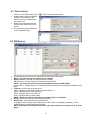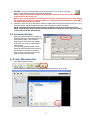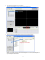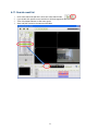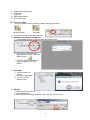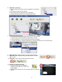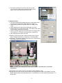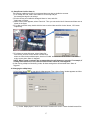
1
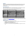
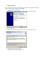
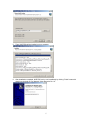
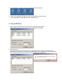
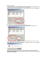
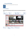
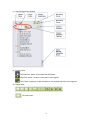
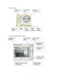
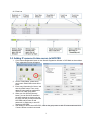
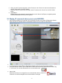
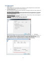
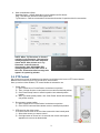
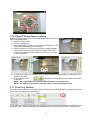
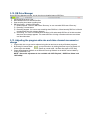
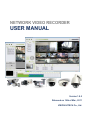
NETWORK VIDEO RECORDER
USER MANUAL
Version 1.0.5
Released on 14th of Mar., 2011
VISION HITECH Co., Ltd.
Table of Contents
About this Document ----------------------------------------------------------------------------------------------- 3
System Requirements --------------------------------------------------------------------------------------------- 4
1. Getting Started ------------------------------------------------------------------------------------------------- 5
2. Set up DB Drive ------------------------------------------------------------------------------------------------ 7
3. Running NVR PRO Main ------------------------------------------------------------------------------------ 9
3-1. User Interface -------------------------------------------------------------------------------------------- 9
3-2. Adding IP cameras & video servers to NVR PRO --------------------------------------------- 12
3-3. Display IP cameras & video servers onto NVR PRO ----------------------------------------- 13
3-4. Group Setup --------------------------------------------------------------------------------------------- 14
3-5. Displaying Group on NVR PRO live viewer ----------------------------------------------------- 15
3-6. Auto Sequence Display ------------------------------------------------------------------------------ 16
3-7. Recording Setup --------------------------------------------------------------------------------------- 16
3-8. Option Setup -------------------------------------------------------------------------------------------- 17
3-9. PTZ Control --------------------------------------------------------------------------------------------- 19
3-10. Digital PTZ and image cropping ------------------------------------------------------------------ 20
3-11. Event Log Window ----------------------------------------------------------------------------------- 21
3-12. DB Drive Manager ------------------------------------------------------------------------------------ 21
3-13. Adjusting the program skin size and video channel movement or change ------------- 21
4. NVR Playback -------------------------------------------------------------------------------------------------- 22
4-1. User Interface --------------------------------------------------------------------------------------------- 22
4-2. Search channel setup ---------------------------------------------------------------------------------- 23
4-3. Start Data Searching ----------------------------------------------------------------------------------- 23
4-4. Searching record data on calendar ----------------------------------------------------------------- 24
4-5. Searching detailed record data on search grid and playback --------------------------------24
4-6. Playback Display ---------------------------------------------------------------------------------------- 25
4-7. Option Setup --------------------------------------------------------------------------------------------- 26
4-8. DB Backup ------------------------------------------------------------------------------------------------ 26
4-9. Secondary Backup -------------------------------------------------------------------------------------- 27
4-10. Open DB backup files --------------------------------------------------------------------------------- 27
4-11. Search event list --------------------------------------------------------------------------------------- 29
5. NVR Event Viewer ---------------------------------------------------------------------------------------------- 30
5-1. Event Viewer User Interface ------------------------------------------------------------------------- 30
5-2. Running Event Viewer --------------------------------------------------------------------------------- 31
6. NVR e-Map ------------------------------------------------------------------------------------------------------- 33
6-1. e-Map User Interface ---------------------------------------------------------------------------------- 33
6-2. Running e-Map ------------------------------------------------------------------------------------------ 34
2
About this Document
Thank you for purchasing VISION Mi- Series and i – Series Network Camera or Network Video
Server(Encoder). This user manual includes instructions for using and managing NVR(Network Video
Recorder) Pro, a video surveillance software, and the IP camera on your network. Networking experience will
be helpful when setting up and using this product. Updated versions of this document will be posted to
www.visionipvideo.com as they become available.
Legal Considerations
Video and audio surveillance can be prohibited by laws that vary from country to country. Please check the laws
in your local region before using this product for surveillance purposes.
Trademark Acknowledgments
Ethernet, Internet Explorer, Linux, Microsoft, Mozilla, Netscape Navigator, OS/2, UNIX, Windows, WWW are
registered trademarks of the respective holders. Java and all Java-based trademarks and logos are trademarks
or registered trademarks of Sun Microsystems, Inc. in the United States and other countries.
Video Standard and Product Classification
(Necessary only for i-Series IP Cameras)
As the video standard varies from country to country, users are asked to check it first and choose the right
model. The two most common video standards used are NTSC and PAL. NTSC is the video system or
standard used in North America and most of South America. In NTSC, 30 frames are transmitted each
second. Each frame is made up of 525 individual scan lines. PAL is the predominant video system or
standard mostly used overseas. In PAL, 25 frames are transmitted each second. Each frame is made up of
625 individual scan lines.
To determine your video standard, refer to the lists below.
PAL: Afghanistan, Algeria, Argentina, Austria, Australia, Bangladesh, Belgium, Brazil, China, Denmark, Finland,
Germany, Hong Kong, Iceland, India, Indonesia, Iraq, Ireland, Israel, Italy, Jordan, Kenya, Kuwait, Liberia,
Malaysia, Netherlands, Nigeria, Norway, New Guinea, Pakistan, Singapore, South Africa, Southwest Africa,
Sudan, Sweden, Switzerland, Thailand, Turkey, Uganda, United Kingdom, United Arab Emirates, Yugoslavia,
Zambia
NTSC: Canada, Chile, Costa Rica, Cuba, Dominican Republic, Ecuador, Japan, Mexico, Nicaragua, Panama,
Peru, Philippines, Puerto Rico, South Korea, Taiwan, USA. Users are asked to read the following before using
the Pro Series Network Camera.
Important Notices
1. Camera surveillance laws may differ for each country. Contact the local authorities to avoid any
surveillance law violations.
2. It is highly recommended that you de-fragment your hard drives on a regular basis to improve
system performance. See your Windows documentation for instructions.
3. Specifications are subject to change without prior notice to enhance the product quality and
stability.
4. The contents of this manual may differ from actual products due to product upgrade or
enhancement.
5. Please read this manual carefully and follow the directions before using NVR PRO.
3
NVR PRO
NVR PRO is an IP or network-based professional video surveillance program enables real time live viewing,
recording, searching and playback. By installing and operating this software into a stable computer system,
state-of-the-art surveillance system can be obtained with all key features necessary for professional
surveillance system.
System Requirements
Please install and operate NVR PRO on a computer dedicated mainly for running this application. Especially
when you use NVR PRO with tens of IP cameras and NVS, dedicated system is needed.
Below minimum system requirement is just for “16 Channel Video and Audio Recording as well as
Live Display & Playback” with each resolution and frame rate.
Resolution and
Max D1 Resolution at 30 FPS
Max HD Resolution at 30 FPS
Frame Rate
CPU
Intel Pentium Dual-Core 2.4 GHz
Intel Core™ i7 3.0 GHz
Graphic Card
128MB or higher
128MB or higher
RAM
2 GB
4 GB
Hard Disk
250 GB
1 TB
Monitor
1024 x 768
1024 x 768
O/S
MS Windows XP Professional SP2 MS Windows XP Professional SP2
MS Windows 7 Home Premium
MS Windows 7 Home Premium
File System
NTFS
NTFS
DirectX
9.0 or later
9.0 or later
Network
10Mbps or higher
100Mbps or higher
The above minimum system requirement varies when you try to install and operate NVR PRO with more than
16 cameras of HD resolution. Please contact those resellers where you bought IP cameras and NVS for better
recommendation or contact [email protected].
NVR PRO contents
NVR PRO consists of 4 kinds of software and they are as follows;
1. NVR Main – Live video monitoring and recording. Shows log messages, connection status, HDD status
and digital zooming or image cropping, etc.
2. NVR Playback – Search recorded data and playback
3. NVR Event Viewer – Live video surveillance when event triggered
4. NVR e-Map – Live video surveillance or monitoring with alarm when event triggered on user defined
map.
4
1. Getting Started
Caution : Please make sure that you de-fragmented your hard drives on a regular basis to improve
system performance before starting setup of NVR PRO.
1. Insert supplied CD on your computer
2. Click “NVR_Pro_x.x_install.exe” to install NVR PRO according to the following process
Click “Next” to continue.
3. When ‘License Agreement’ dialog box appears, check on the check-box and click ‘Next’.
4. Define destination folder and click “Install”
(Default folder is C:\Program Files\NVR Pro 1.0\)
5
5. Then, NVR PRO will be installed on your computer.
6. After installation completed, NVR PRO can be run immediately by clicking ‘Finish’ button with
check-box checked on ‘Run Network Video Recorder Pro 1.0’.
6
7. After installation, 4 shortcut icons will be created on desktop as follows;
8. When you try to delete NVR PRO, you may run uninstall.exe on below location.
Start-up MenuÎAll ProgramsÎNVR PRO 1.0ÎUninstall.exe
2. Set up DB Drive
1. Before using NVR PRO, DB Drive should be set according to below process.
Below DB Drive Setting window appears when you initially run NVR PRO.
2. DB Drive Setting
Select DB Drives among those drives on your computer except for system drive as shown above.
When there is only one drive, your computer and NVR PRO may be unstable while running. In this case,
below warning message comes just after you check system drive as a DB Drive.
7
3. DB Max. Size Setting
Set the maximum DB size for the selected DB Drive by GByte. Set DB Size by clicking up-down key or
enter specific number in the DB Size Setting box and click ‘Create’ button.
NOTE : DB Size can be set up to total free size of selected DB Drives. Free size is 5 GByte less
than total size for recovery purpose, etc.
4. When DB size is full, two kinds of action can be selected.
1) Stop recording : Immediately stops recording when set DB size is full.
2) Overwrite : Continues recording by overwriting on the oldest data when set DB size is full.
5. If DB setting failed and/or DB opening failed, below error messages shows and in this case, only live
video is available even though NVR PRO is running.
Without administrator authorization, DB Setting is not available and in this case, this error may happen.
NOTE : When NVR Main is closed with abnormal or unexpected termination, DB Recovery
window appears when NVR PRO restarted as shown below. If you click ‘Recovery’ button, then
DB recovers automatically.
8
3. Running NVR PRO Main
Double click “NVR Pro” icon on the desktop then NVR Pro will be started.
3-1. User Interface
This chapter provides a brief description of NVR PRO user interface, control buttons and menu options from the
main view. For more detailed description of buttons and menu items refer to the details in each chapter of this
manual.
9
(1) Status & Registration Window
(2) Program Icons
NVR Playback : Search of Recorded Data & Playback
NVR Event Viewer : Shows live video when event triggered
NVR E-MAP : Displays live video and alarm on user defined map when event triggered
(3) Display Mode
Shows live video in 1/4/6/9/10/11/16/25/36/49/64 channel mode.
Full screen mode.
10
(4) PTZ Control
(5) Digital PTZ and Image Cropping
11
(6) Event Log
(7) DB Drive Manager
3-2. Adding IP cameras & video servers to NVR PRO
1. Click ‘Camera Registration’ button on the ‘Status & Registration Window’ of NVR Main as shown below.
Then, registration window will appear.
2. On the ‘Folder Name’, please enter
group name. Blank folder name will be
‘Root’.
3. Enter every information for ‘Server’ and
then click ‘Add’ button. Then, newly
added IP camera will be appeared on
‘Server List’ under group name.
4. When you click ‘Server Discovery’
button, you can find all IP cameras in
the same network environment on the
list. Click one that you want to add onto
NVR PRO and just enter IP and
password. It’s easier way to enroll IP
camera to NVR PRO.
5. After adding IP camera onto NVR PRO, check on the group name or each IP camera name and click
‘Connect’ button to make it connected.
12
6. When you edit IP camera information, select IP camera on the ‘Server List’ and revise information on
the right. After revision, click ‘Edit’ button.
7. When you delete IP camera from NVR PRO, select IP camera on the ‘Server List’ and click ‘Delete’
button.
8. Import/Export
Enables saving of the existing IP camera information on the ‘Server List’(Export) or registering saved
IP camera information onto ‘Server List’.(Import)
3-3. Display IP cameras & video servers onto NVR PRO
1. After finishing registration of IP cameras, all IP cameras are shown on the ‘Status & Registration Window’.
Drag and drop one selected camera on the display window to see live video from that camera.
2. When you want to remove specific camera from live view, click that video window. Then drag and drop it
in reverse direction toward ‘Status & Registration Window’ as shown in the above with red arrow.
3. Even after doing as 1 above, if you cannot see live video, then the camera is disconnected or failed to log
in. In this case, you can see disconnection icon on the camera name.
4. Alarm In/Out
When there is alarm in or out signal from or to external alarm device, ‘Alarm In’ or
‘Alarm Out’ icon will be changed into red color as shown on the right.
13
5. Camera Connection, Audio, Microphone, Alarm can be on or off by context menu with right button of
mouse clicked. (See below)
6. This context menu can be utilized by clicking right mouse
button on a video screen as shown below.
3-4. Group Setup
To make similar or related IP cameras into one group is very convenient for management and this function is
just for that purpose.
1. Click ‘Group Tab’
and ‘Set Group List’ tab
group registration window appears as shown below.
on the ‘Status & Registration Window’. Then
2. Enter group name, description, auto sequence time (by second) and display mode one by one and click
‘Add’ button. Then new group name will appear in the ‘Group List’ on the right.
3. Drag and drop cameras from ‘Server List’ to group name on the ‘Group List’, then click ‘OK’ button.
4. If you try drag & drop of same stream into same group, then there comes warning message as follows.
14
5. You may move cameras from group to group by drag & drop.
6. If you want to delete camera from group list, select that camera and drag & drop in reverse way.
(See red arrow in the above)
Or you may click delete key on the key board after selecting that camera.
(Confirm deleting by clicking ‘Yes’ button)
3-5. Displaying Group on NVR PRO live viewer
1. Click ‘Group Tab’ on ‘Status & Registration Window’. Then all registered groups appear on the list.
2. Just select one group, then drag and drop it on the live view window. Then live videos from cameras on
this group display on the screen in pre-defined display mode.
3. Turning on from the context menu by clicking right button of mouse also
enables live video of group on the screen.
15
3-6. Auto Sequence Display
Auto sequence function shows the video of each camera or group by switching into one by one. Each channel
lasts during the set sequence time.
1. To start auto sequence in server mode, just click ‘Auto Sequence’
button after setting the auto sequence time.
2. Then each channel switches one by one after auto sequence time.
3. In gourp mode, just click ‘Auto Sequence’ button as auto sequence
time is already set when group is registered.
3-7. Recording Setup
Recording setup is available by clicking ‘Set Rec Info’ tab on the ‘Status & Registration Window’.
1. Click ‘Set Rec Info’ tab on the ‘Status & Registration Window’.
2. On the right window, all rgistered
cameras are shown. Select camera,
the drag and drop on a specific DB
channel and check on the check box.
3. For dtailed recording setup, click
‘Schedule’ button as follows.
Then, ‘DB Recording Schedule Setup’ windows opens as
follws. Check on the check box of ‘Continue’ or ‘Event’.
Continue’ means continuous recording, which records all video
according to the set schedule. ‘Event’ means event recording
and recording happens only when event is triggered.
16
To plot recording
scheule, please click
mouse button and
draw a rectangular
area on the time
table.
All above recording
setup is available for
both streams of
H.264 and MJPEG.
(Stream1 and 2)
4. If you check on the
‘Audio’, audio as well
as video will be
recorded.
5. On the bottom, there
is ‘Pre/Post alarm’
setting.
Pre-alarm means
video before event
trigger and you may set 1~5 seconds pre-alarm video.
Post-alarm means video after event trigger. 1~180 seconds can be set for post-alarm video.
6. After setting up all these recording issues, then please make sure to click ‘OK’ button before exit.
7. When recording is started, there is red mark on top right corner of each video.
8. When ‘Event’ recording is set on the schedule and event
triggered, there is event trigger icon on bottom left of each
video.
17
3-8. Option Setup
1. Display Caption
Check on the check box for information to be included on the video image skin such as camera name,
recording status icon, event trigger and audio recording icon.
2. Live Video Display Option
Video recording has priority than live video in NVR PRO. To manage live video from many cameras, one
of the three options is to be selected.
Auto display control for delayed frame – Skip the frame delayed over the pre-defined time. For example,
if 3 seconds is set for this, then those frames delayed over 3 seconds are skipped and not displayed in
live video. (Recommended)
Keep original frame rate – Always keeps original frame rate. Jumpy or jerky live video can be happened
in this mode due to network bandwidth.
i-Frame only – Displays i-Frame only on the live video window.
NOTE : Please make sure to click ‘OK’ button before exit.
3.
DB Setting
DB Drive Setting, DB Max. Size Setting can be changed here. Also the additional action on DB Drive, i.e.
whether to stop recording or to continue recording by overwriting can be changed as well.
NOTE : Application will be terminated when there is change in DB setup. Users should restart
NVR PRO and in this case, changed DB setting will be adopted upon restarting.
18
4. Other miscellaneous Setup
Snapshot Option – defines destination to save snapshot and file format.
Ping – Sets the time interval to check system alive.
Try Reconnect – Defines reconnection trial interval and number of repetitive trials for reconnection.
NOTE : When ‘Try Reconnect’ is checked
and there is disconnection, ‘Reconnecting’
message appears on the video window as
shown below. After all trials set in ‘Try
Reconnect’, and still camera is
disconnected, then ‘DISCONNECTED’
message appears on the video screen. In
this case, ‘Connection failed’ message also
appears on system log window.
3-9. PTZ Control
Pan, tilt and zoom control of camera can be done by just clicking on the icons on PTZ control window.
Below are the function keys for PTZ as well as iris, focus control.
Once you select a video window, PTZ control window is activated to use.
1. Preset Setup
1) Open combo box on ‘Preset Position’ and select one position.
2) Then, click pan tilt zoom control panel to move camera to desired position.
3) Click ‘Preset Setup’ button to save this position into selected position
number.
4) When you delete preset position, click ‘Clear Preset’ button after selecting
one position number.
2. Run camera to preset position
1) Open combo box on ‘Preset Position’ and select one position.
2) Click ‘GOTO’ button and then camera moves to saved preset position.
3. PTZ control on the video screen.
PTZ control can be done on the live video screen with virtual control panel.
1) Select video screen you want to control.
2) Click right button of mouse for 2~3 seconds, then virtual control panel
appears on the screen as shown below.
19
3-10. Digital PTZ and image cropping
NVR PRO enables digital PTZ as well as digital image cropping in both live
viewer and playback mode.
1) Select one video channel
2) Check on ‘Digital Zoom’
3) Draw a rectangular line with your mouse and then this portion of the
video will be zoomed as shown in the figure.
4) When you position your mouse point around the middle of digitally
zoomed part, then the pointer becomes cross arrow mark. Then
click mouse button and move this mark left and right, up and down
to see pan tilt control.
5) In digital zoom mode, you can save or print out digitally zoomed (cropped) image by clicking either save
button or print button.
6) Cropped image can be
adjusted by clicking brightness and contrast control slide
on the right.
NOTE : Only cropped image is recorded in DB drive when you do digital zoom.
NOTE : This digital PTZ and image cropping function is same in the playback mode..
3-11. Event Log Window
Event log window shows every event log message expressing motion detection, alarm-in, system disconnection
or failure and user defined log messages, etc.
Those event log messages can be saved as a file or printed out by clicking related buttons on top right of event
log window. (Max. 1,000 log messages (100 messages for Lite version) can be saved into *.csv file format)
20
3-12. DB Drive Manager
On the DB Drive Manager window, we can check every detailed status of DB Drive.
1.
2.
3.
4.
Percentage of DB Drive used
Recorded DB size over total DB Set Size
Start recording time~latest recording time
DB Drive Status – 4 kinds of DB status
1) DB Not Opened : Failure in ‘DB Create / Recovery’ or user canceled ‘DB Create / Recovery’.
2) Recording : Normal status
3) Recording stopped : If it is set to stop recording when DB Drive is full and actually DB Drive is full with
recorded data, then this message appears.
4) Overwriting : If it is set to overwrite when DB Drive is full and actually DB Drive is full with recorded
data, then this message appears. This means DB Drive is being overwritten with new record data
over the oldest data.
3-13. Adjusting the program skin size and video channel movement or
change
1. Program skin size or type can be adjusted using title bar and mouse as other Windows programs.
2. By clicking full screen button
on top of the skin or by clicking Alt+Enter key on key board, full
screen mode is available.
(Retrun to normal mode : Alt+Enter Key again or ESC Key)
3. ‘Status & Registration Window’ on the left and ‘Event Log Window’ on the bottom can be hidden by
clicking ‘Show/Hide’ icon.
NOTE : Above skin adjustment is also available with ‘NVR Playback’, ‘NVR Event Viewer’ and
‘NVR e-Map’.
21
4. NVR Playback
4-1. User Interface
(1) Program Icons
: NVR Main
: NVR Event Viewer
: NVR e-MAP
Display Mode : Up to 16 channel, 7 types of playback display mode are available.
System time
NVR information showing version
Setup Window : Channel setup, Backup, Open backup files, Option setup and event search, etc. are
available in this window
(6) Calendar showing recorded data
(7) Digital PTZ window
(8) Data search grid
(2)
(3)
(4)
(5)
22
4-2. Search channel setup
1. Click channel setup button. Then, channel setup window opens.
2. Check on the
channel to search
recorded data and
click OK button.
3. All these checked channels will appear on the window as a
tree
4-3. Start Data Searching
1. Just drag and drop
either group name
or camera name on
the display screen.
2. Then, on the
calendar, the dates
with recorded data
will be distinguished
and the latest data
will be shown on
the search grid as a
colored bar.
Drag & Drop
23
4-4. Searching
S
g record data on calendar
c
1.
Select specific date (for example
e
in above fiigure ) and cliick search(
) button.
2.
To refresh ca
alendar, click ‘Refresh’ buttton.
3.
For today’s data,
d
just click ‘Today’ buttton.
4.
5.
6.
Formerr or next year and month re
espectively.
o recorded da
ata on a specific date, all re
elated buttonss are inactivatted.
If there is no
After selectin
ng specific da
ate, then go to
o search grid to do more detailed
d
searcch.
4-5. Searching
S
g detailed
d record data on search
s
grrid and pllayback
1. On a search grid, colored bar shows detailed record
d information..
Record datta with more than
t
20 Fram
mes per secon
nd
Record datta with more than
t
10 Fram
mes per secon
nd
Record datta with less th
han 10 Frame
es per second
d
Audio record data
Event recorrding. The red
d color showss the point when event trigg
gered and pin
nk color show
ws pre or
post alarm record.
Blank with no colored ba
ar indicates no
n record data
a.
2. Another
A
way of detailed se
earch is availa
able by splitting search tim
me into severa
al units search
h as 1
h
hour,
30 minutes, 10 minuttes and 5 min
nutes.
W
When
you click
k time button((
), all
a these deta
ailed types appear as show
wn below.
3. When refresh
hing the record data, click refresh button.
4. Video Playba
ack buttons on the Search Grid and their functions
Stop
Reverse
R
Play / Forward Pla
ay
One
O frame revverse play / One
O frame forw
ward play
Move
M
to the firrst point / Move to the last point
5. Searching fo
or specific eve
ents only
Search
hes motion de
etection eventts only
Search
hes alarm eve
ents only
NOTE : When
N
n the above two
t
buttons or one of the
e two button
ns selected, only
o
notion detection
d
e
event
or alarm
m event reco
ord is being played
p
back
k. If these butttons are res
set, then all record
r
d
data
will be played
p
back.
6. Audio Playb
back button
is activvated only wh
hen one channel is selecte
ed and displayyed
Then, audio can be played
d back by cliccking this buttton. During th
he audio playb
back, audio iccon will be
displayed on the bottom riight of screen
n. (This icon can
c be either displayed
d
or hidden
h
accord
ding to the
setting of ‘Dis
splay’ on NVR
R PRO Main ‘Option’ menu
u)
24
7. Playback Speed : Max. playback speed differs from number of playback channel as follows.
This playback speed can be selected on the search grid by sliding the button.
1 Channel : Max. X16 speed playback
Up to 4 Channel : Max. X8 speed playback
Up to 8 Channel : Max. X4 speed playback
Over 9 Channel : Max. X2 speed playback
8. Data search time and changing the time.
On the time window of search grid displays the data search time and this time is
changeable by enter new time of by clicking up down key on that window.
9. When system time has been changed into earlier time, overlapped recording may happen. In this case,
NVR PRO adds index onto DB to distinguish and search these overlapped data.
When there is overlap data, index search window on search grid is activated to search data by index. The
larger index number indicates recent record data.
10. Direct search on search grid
By clicking the black line with mouse button and drag it to desired search time, users can search record
data directly on the search grid.
4-6. Playback Display
1. Display mode is the same as NVR Main but max. 16
channel display is available and there is no full screen
mode.
2. If you click right button of mouse on a video playback
screen, context menu appears as shown below.
By clicking either ‘Save Image’ or ‘Print Image’, you can
save the selected image as a snapshot or print out from
the printer.
25
4-7. Option Setup
1. When you click ‘Option setup’ button (
2. Display caption determines whether
Channel, Time, Audio icon and
Event icon are to be displayed on
the screen or not.
3. Data/Time Format determines the
format to show system time on the
screen.
4. ‘Etc’ defines the path and file name
to save snapshot image.
), setup window opens as follows.
4-8. DB Backup
1. If DB Backup button is clicked, DB Backup window is opened as follows.
A
2. On DB channel on the top left, you may select DB channels to make backup.
NOTE : In AVI format, only one channel can be selected.
3. Backup Format : Two kinds of backup format are available.
DB File format – Creates backup file in same format as NVR DB.
NOTE : This file format can be searched and played back only with NVR Playbck.
AVI File format – Creates backup file in standard avi file format and it can be played with standard media
player.
4. Contents : Selects contents of backup file
Video – Backups all video data including event recording, etc.
Motion – Backups motion event video only.
Alarm – Backups alarm event video only.
Audio – Backups audio as well as video.
NOTE : Motion and Alarm can be selected only when ‘Video’ is unchecked.
5. Range : Defines the start point and end point for backup.
6. Backup Size : Helps estimating the backup DB size.
Overlapped record data also can be checked here. When there is overlapped record data, you may
select DB index on the DB index search window.
NOTE : When there is overlapped record data, index search window is activated. (see ‘A’ in above
figure)
26
7. File Path : You may enter path and file name for backup file. Or you may click ‘Browse’
button to open Windows Explorer and define backup path.
NOTE : Backup onto former backup file is available but in this case, new backup data will be
overwritten over the former one.
Backup files can be played back in NVR Playback but when you do backup over the open backup
file for playback, it may cause serious problem. So, checking the file path whether it is open DB or
not before starting backup is needed.
8. Start/Stop : When you click ‘Start’ button, backup is started and the progress is shown on the bar. If you
click ‘Stop’ button before completion of backup, then backup terminates immediately.
NOTE : Immediate termination of backup before completion may hinder normal data search.
NOTE : When backup started without selecting DB index for overlapped record data, then backup
is done with latest data automatically.
4-9. Secondary Backup
While looking at the backup file, additional
secondary backup can be made by clicking
backup button again. This secondary
backup can be useful when the original
backup file is too large to search specific
data from that.
The secondary backup window is quite
similar as initial DB Backup but instead of
selecting file format, backup file path is
shown on top. The whole process is the
same as initial backup process.
4-10. Open DB backup files
1. Click ‘Backup Search’ button.
And then explorer window will be opened. Find backup file and click ‘Open’ button.
27
2. Then, backup file will appear in the tree as follows.
Drag and drop the backup file on to the screen and click playback button.
Drag & Drop
3. Backup file can be open by drag and drop or double click from Windows Explorer.
Drag & Drop or Double Click
NOTE : If you double click backup file when NVR Playback is not executed, NVR Playback will
open as backup file search mode.
28
4-11. Search event list
1.
2.
3.
4.
Click event search tab and then it turns into event search mode.
If you double click specific event, search time will be changed into that event time.
Then click playback button to view event record.
Save and print function is the same as NVR Main.
29
5. NVR Event Viewer
5-1. Event Viewer User Interface
1. Program Execution Icons
NVR Main
NVR Playck
NVR e-Map
2.
3.
4.
5.
6.
7.
Display Mode Button : Same as NVR Main
System Time
Program version information
Event Video Display
Detailed Information about Event Video
Event info Show/Hide button
30
5-2. Running Event Viewer
1. Connect to IP camera and set emergency as below.
Configuration Î Event Î Notification Î Check and enter related info on CMS
2. When emergency happens, event info will appear on (6) event info window and event video will appear
on the screen during the defined ‘Dwell Time’.
Video will show on the first blank screen.
31
3. Option Setup : Click ‘Option setup’ button on the top right of event info window and setup window will be
opened.
Check on ‘Display Caption’ and define snapshot option respectively.
4. Display Mode, Show/Hide Function, Context Menu on the screen, Event Info, etc are all same as NVR
Main.
32
6. NVR e-Map
6-1. e-Map User Interface
(3)
1. Program Execution Icons
NVR Main
NVR Playck
NVR Event Viewer
2. Map Manager
3. System Time
4. Program version information
33
5.
6.
7.
8.
9.
Registration & Option Setup
PTZ Control
Digital PTZ
Map Display Window
Event Info Window
6-2. Running e-Map
1. Turns into e-Map edit mode by clicking e-Map monitoring mode button.
Monitoring Mode
Edit Mode
2. Click Map List button to see registered map
3. Add Map to Map Window and Map List
1) Click Add Map button or click on the blank map window button.
2) Enter map name and define the
image path by clicking the Windows
Explorer button
3) Click ‘OK’ and then selected map
image will appear on the map
window.
4. Delete Map
1) Select map from the
map list.
2) Click Delete Map button
3) Click ‘Yes’ to finish
deletion of map.
5. Edit Map
1) Select map from the map list
2) Click Edit Map button
3) Edit map name and change image path. Then click ‘OK’ button to finish.
34
6. Add items on the map
1) Camera, Alarm In and Alarm Out can be added on the selected
map
2) Click server list and connect camera
3) Then Video, Alarm In and Alarm Out will activated.
4) Drag and drop these items on the map as shown below
Drag & Drop
7. Delete items from the map
1) Select item on the map and press ‘Delete’ key on the key board.
2) Or select item on the map and click right button of mouse.
3) Select ‘Delete item’ on the context menu as shown in the figure.
4) Or select item from the map list and delete it by selecting ‘Delete item’ on the context menu.
8. Move map item : Map items can be moved by drag and drop
9. Save map : Save map by clicking ‘Save Map’ button. File name
will be *.map.
10. Open map : Open map by clicking ‘Map Open’ button
11. Pop-up Live Video on the map
1) Connect camera and turn e-Map into
monitoring mode (Be sure to check if it is
locked image)
2) Double click the camera icon on the map and then live video will
pop up.
35
3) By clicking right button of mouse on the pop-up video,
you may turn on audio and microphone as shown in the
figure. Or you may close pop-up video as well.
12. Setup Event Link
1) This function determines whether pop up live video and/or alarm
out when event triggered by motion detection or alarm-in.
2) Before setting up event link, please make sure e-Map is ‘Edit
mode’.
3) Select camera on the map and click right button of mouse.
4) Select ‘Event Link’ on the context menu. Then, below ‘Video event
link information’ window will be opened.
5) Check on ‘Enable’ and check on the sub menu’s of ‘Pop-up video’,
‘Run panorama’, ‘PTZ preset’ and ‘Sound play’, respectively.
6) After setting all above items, click ‘OK’.
■ Duration under ‘Pop-up video’ means the lasting time of pop-up
video. Duration can be set as ‘Continuous’ or 15~60 seconds.
■ Panorama : This function shows a sequence of pre- and post-event
video image when event triggered.
NOTE : In e-Map, pre- and post-event time can be set as 1~3 seconds and 1~5 seconds,
respectively.
■ PTZ Preset is to be set as ‘None’ or one specific number between 1~256.
■ Sound play is a function to play wave file when event triggered. Sound play is selectable one among
NONE, Window Beep or any desired wave file. To add wave file or remove wave file, press either + or –
button there.
36
13. Setup Event Link for Alarm In
This function enables event link for camera and alarm-out that are inside the set area.
1) Turn e-Map into ‘Edit’ mode. Select Alarm In on the map and pull
the rectangular edge line to enlarge.
2) Put the mouse point inside this enlarged ‘Alarm In’ area, and click
right button of mouse.
3) When context menu appears, select ‘Event link’. Then you can see the list of Cameras and Alarm-out as
shown in the figure.
4) For video event link setup, double click the item or select video and click ‘Action’ button, ‘’OK’ button
respectively.
5) For Alarm-out event link setup, select ‘Alarm Out’
from the list, and click ‘Action’ button or double click
alarm-out. When below window opens, check on ‘Enable’ and select one of the ‘Action’. This selected
action occurs when ‘Alarm-In’ happens.
NOTE : When Toggle is selected, the accompanied action will happen as reversely. For example, if
existing alarm-out is set as ‘On’, then it will be off when ‘Alarm In’ event happens.
6) After turning e-Map into ‘Monitoring’ mode, all those setting above will activated when ‘Alarm In’
triggered.
14. Changing the e-Map Setup
1) Click ‘Setup’ button(
) on top right of e-Map program. Then ‘Option Setup’ window appears as follow.
2) On the ‘Display Option’, check on the items to reveal on the screen. These checked items will be
37
shown as an ‘On screen display’ on the live video pop-up.
3) And set the ‘Pre-time’ and Post-time’ respectively on the ‘Panorama’. Panorama image will pop up
during ‘Pre-time+Post-time’ when event triggered. Pre-time can be set as 1~3 seconds while
Post-time 1~5 seconds.
4) Etc. is same as NVR Main.
Vision Hitech Co., Ltd. offers a complete line-up of network video products and solution. Ask
your local dealer for more information or visit www.visionipvideo.com
Copyright © Vision Hitech Co., Ltd.
All products mentioned are trademarks or registered trademarks of their respective owners.
38