1
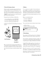
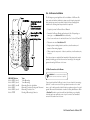
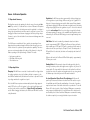
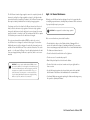
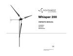
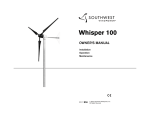
Owner’s Manual Installation Operation Maintenance Southwest Windpower, Inc. 1801 West Route 66 Flagstaff, Arizona 86001 Toll Free Phone: 866.805.9463 Phone: 928.779.9463 Fax: 928.779.1485 www.airbreeze.com September 2008 Southwest Windpower, Inc. All Rights Reserved Southwest Windpower Congratulations on your purchase and welcome to our family! Dear Air Breeze Owner, Thank you for your purchase of Air Breeze. You have purchased the most advanced battery charging wind turbine in the world! We believe you will find it easy to install your Air Breeze and are confident you will experience years of dependable service from it. Before going any further, please complete and return the Warranty Registration Card. Note - Southwest Windpower does not sell or distribute your personal information to any third party. We understand and respect your privacy. If you have any questions or comments, we would like to hear from you. Please call during working hours (Monday-Friday – 8:00am to 5:00pm Arizona Standard Time). Our numbers are 928-779-9463, toll-free 866-805-9463. Again, welcome to our family and thank you for investing in the future of wind energy with Air Breeze. Sincerely, Southwest Windpower Enter the serial and model numbers below Air Breeze Installation Manual Document No. 3-CMLT-1327-01 Revision: B Serial Number __________________________________ Model Number __________________________________ AIR, AIR 403, AIR-X, AIR Wind Module are trademarks of Southwest Windpower 2007 Southwest Windpower, Inc. Air Breeze Owner’s Manual One - Important Safety Instructions Read these instructions in their entirety before assembling, installing or operating your air breeze 1) SAVE THESE INSTRUCTIONS. This manual contains important instructions that must be followed during assembly, installation and maintenance. 2) Read, understand and respect all warnings. 3) Do not install Air Breeze on a windy day. 4) If unusual noise or operation is experienced, turn off machine and contact authorized service personnel. 5) During assembly and installation properly torque all fasteners. 6) Use only proper grounding techniques as established by the NEC. 7) Properly complete the Warranty Registration Card. 8) Breeze must be installed in accordance with this manual and local and national build- ing codes. Failure to comply with this manual and local codes may affect and possibly void your warranty. 9) Rotating blades are a serious mechanical hazard. Install Air Breeze so no one can come into contact with blades. 10) Observe wire size and fuse recommendations listed in the Wiring Section of this manual. In this manual you will see the following icons: IMPORTANT: Indicates instruction or advice that is critical for correct assembly or operation. Damage to equipment may result if not heeded. TIP: Indicates instruction or advice that may simplify or ease task or operation. WARNING: Indicates risk of severe injury or death or possible severe damage to equipment - proceed with caution and follow instructions. LAND USE: Specific to Land Use. MARINE USE: Specific to Marine Use. Air Breeze Owner’s Manual Contents 1) important Safety Instructions___________________ 4 7) AIR BREEZE OPERATION______________________________ 23-25 Warranty_ _________________________________________ 6 7-1 Operational Summary______________________________ 23 TECHNICAL SPECIFICATIONS_ ________________________ 7 7-2 Operating Modes_ ________________________________ 23 2) TURBINE ASSEMBLY_ ________________________________ 8 7-3 Voltage Regulation________________________________ 24 3) SITING_______________________________________________ 9 7-3-1 Adjusting Regulation Voltage___________________ 24 4) TOWERS_____________________________________________ 10 7-3-2 Using an Alternate Charge Controller____________ 24-25 4-1 Tower Options____________________________________ 10 8) MAINTENANCE_______________________________________ 25 4-1-1 27 ft (8.3 m) Tower Kit________________________ 11 9) TROUBLE SHOOTING_________________________________ 26 4-1-2 29 ft (8.8 m) Tower Kit________________________ 11 10) EXPLODED VIEWS & PARTS LIST_ ____________________ 28-29 4-1-3 45 ft (13.7 m) Tower Kit_ _____________________ 12 11) EC DECLARATION OF CONFORMITY_ _________________ 30 4-1-4 Marine Tower Kit ____________________________ 12 5) WIRING OPTIONS_____________________________________ 13-14 5-1 Hybrid System Wiring______________________________ 15 5-2 Multiple Air Breeze Wiring__________________________ 16 5-3 Wire Size________________________________________ 17-18 5-4 Stop Switch______________________________________ 18 5-5 Fuses, Circuit Breakers, Ammeter____________________ 19 5-6 Batteries_ _______________________________________ 19 5-7 Turbine Grounding________________________________ 19-20 5-8 Tower Grounding_ ________________________________ 20 5-8-1 Electrodes Driven in Soil______________________ 20 6) INSTALLATION_ ______________________________________ 21 6-1 Wire Connections_________________________________ 21 6-2 Mounting on Tower________________________________ 22 6-3 Final Connections_________________________________ 22 Air Breeze Owner’s Manual Air Breeze 3-Year Limited Warranty Wind Turbine Warranty Agreement Hardware Warranty Southwest Windpower, Inc., (“Southwest Windpower”) will repair or replace free of charge any part or parts of the Southwest Windpower Air Breeze (Land or Marine) Wind Turbine determined by Southwest Windpower to be defective in materials and/or workmanship under normal authorized use consistent with product instructions for a period of three years from the date the original purchaser (“Customer”) receives the Wind Turbine (“Start Date”). This warranty extends only to the original purchaser. The Customer’s sole and exclusive remedy and the entire liability of Southwest Windpower, its suppliers and affiliates under the warranty is, at Southwest Windpower’s option, either (i) to replace the Wind Turbine with new or reconditioned Wind Turbine; (ii) to correct the reported problem; or (iii) to refund the purchase price of the Wind Turbine. Repaired or replaced products are warranted for the remainder of the original warranty period. Restrictions Problems with the Wind Turbine Products can be due to improper use, improper maintenance, non-Southwest Windpower additions or modifications or other problems not due to defects in Southwest Windpower’s workmanship or materials. No warranty will apply if the Wind Turbine (i) has been altered or modified except by Southwest Windpower; (ii) has not been installed, operated, repaired, or maintained in accordance with instructions supplied by Southwest Windpower; (iii) or (iv) has been exposed to winds exceeding 120 mph (54 m/s), or has been subjected to abnormal physical, thermal or electrical stress, misuse, negligence, or accident. If Southwest Windpower’s repair facility determines that the problem with the Wind Turbine is not due to a defect in Southwest Windpower’s workmanship or materials, then the party requesting warranty service will be responsible for the costs of all necessary repairs and expenses incurred by Southwest Windpower. Warranty Claims & Return Procedures In order to be eligible for service under this warranty, the Customer must submit a service request for Wind Turbine covered by this warranty within the warranty period by contacting Southwest Windpower in writing or via telephone and obtaining a Return Authorization (“RA”) number. This RA must be obtained before returning any product under this warranty. Notification must include a description of the alleged defect, the manner in which the Wind Turbine was used, the serial number, and the original purchase date in addition to the name, address, and telephone number of the party requesting warranty service. Within 3 business days of the date of notification, Southwest Windpower will provide the Customer with an RA number and the location to which the Customer must return the defective Wind Turbine. Any Wind Turbine requiring warranty shall be transported at the expense and risk of the party requiring warranty service, including but not limited to proper packaging of the Product. The Customer must return the entire Wind Turbine kit within 30 days after issuance of the RA number. Southwest Windpower will be Air Breeze Owner’s Manual under no obligation to accept any returned Wind Turbine that does not have a valid RA number. Customer’s failure to return the Wind Turbine within 30 days of its receipt of an RA number may result in cancellation of the RA. All parts that Southwest Windpower replaces shall become Southwest Windpower’s property on the date Southwest Windpower ships the repaired Wind Turbine or part back to the Customer. Southwest Windpower will use all reasonable efforts within five days of receipt of the defective Wind Turbine to repair or replace such Wind Turbine. If a warranty claim is invalid for any reason, the Customer will be charged at Southwest Windpower’s then-current rates for services performed and will be charged for all necessary repairs and expense incurred by Southwest Windpower. Disclaimer EXCEPT FOR THE EXPRESSED WARRANTY SET FORTH ABOVE, SOUTHWEST WINDPOWER DISCLAIMS ALL OTHER EXPRESSED AND IMPLIED WARRANTIES, INCLUDING THE IMPLIED WARRANTIES OR FITNESS FOR A PARTICULAR PURPOSE, MERCHANTABILITY AND NON-INFRINGEMENT. NO OTHER WARRANTY, EXPRESSED OR IMPLIED, WHETHER OR NOT SIMILAR IN NATURE TO ANY OTHER WARRANTY PROVIDED HEREIN, SHALL EXIST WITH RESPECT TO THE PRODUCT SOLD UNDER THE PROVISIONS OF THESE TERMS AND CONDITIONS. SOUTHWEST WINDPOWER EXPRESSLY DISCLAIMS ALL LIABILITY FOR BODILY INJURIES OR DEATH THAT MAY OCCUR, DIRECTLY OR INDIRECTLY, BY USE OF THE PRODUCT BY ANY PERSON. ALL OTHER WARRANTIES ARE EXPRESSLY WAIVED BY THE CUSTOMER. Limitation of Liability UNDER NO CIRCUMSTANCES WILL SOUTHWEST WINDPOWER OR ITS AFFILIATES OR SUPPLIERS BE LIABLE OR RESPONSIBLE FOR ANY LOSS OF USE, INTERRUPTION OF BUSINESS, LOST PROFITS, LOST DATA, OR INDIRECT, SPECIAL, INCIDENTAL, OR CONSEQUENTIAL DAMAGES OF ANY KIND REGARDLESS OF THE FORM OF ACTION, WHETHER IN CONTRACT, TORT (INCLUDING NEGLIGENCE), STRICT LIABILITY OR OTHERWISE, RESULTING FROM THE DEFECT, REPAIR, REPLACEMENT, SHIPMENT OR OTHERWISE, EVEN IF SOUTHWEST WINDPOWER OR ITS AFFILIATE OR SUPPLIER HAS BEEN ADVISED OF THE POSSIBILITY OF SUCH DAMAGE. (Note: some states and provinces do not allow the exclusion or limitation of incidental or consequential damages, so these limitations may not apply to you.) Neither Southwest Windpower nor its affiliates or suppliers will be held liable or responsible for any damage or loss to any items or products connected to, powered by or otherwise attached to the hardware. The total cumulative liability to Customer, from all causes of action and all theories of liability, will be limited to and will not exceed the purchase price of the Product paid by Customer. This warranty gives the Customer specific legal rights and the Customer may also have other legal rights that vary from state to state or province to province. 3-CMLT-1331 REV NC 10-07 Air Breeze Technical Specifications Model Air Breeze Weight 13 lb / 6 kg Rotor Diameter 46 in / 1.17 m Start Up Wind Speed 6 mph / 2.7 m/s Kilowatt Hours/month 38 kWh/month @ 12 mph / 5.4 m/s avg. wind speed Maximum Wind Speed 110 mph Rated Power 160 watts @ 28 mph / 12.5 m/s wind speed Certifications CSA (certificate 1954979) 24.5 in radius (61 cm) Operating Temperature Range Air Breeze is certified under IEC requirements applying to the temperature range 14º F (-10º C) to 104º F (40º C) 12 volt and 24 volt Air Breeze wind turbines are eligible to bear the CSA mark with “C” and “US” indicators. The “C” and “US” indicators signify that the product has been evaluated to the applicable CSA and ANSI/UL standards for use in Canada and the US. Voltage Regulation Set Point (factory setting) 12 Volt Systems 14.1 Volts 24 Volt Systems 28.2 Volts 48 Volt Systems 56.4 Volts 26.6 in (67.5 cm) 46 in (1.15 cm) Regulator Adjustment Range 12 Volt Systems 13.6 to 17.0 Volts (approximately) 24 Volt Systems 27.2 to 34.0 Volts (approximately) 48 Volt Systems 54.4 to 68.0 Volts (approximately) Recommended Fuse Size 12 Volt Systems 20 amp (slow blow) 24 Volt Systems 10 amp (slow blow) 48 Volt Systems 5 amp (slow blow) 22.5 in (56 cm) minimum safe pole length above obstructions 2.0 in (5 cm) Tower Loads Shaft Thrust* 52 lb @ 100 mph wind speed (230 N @ 45 m/s) *Value does not include safety factor. SWWP recommends safety factor of 1.5. Air Breeze Owner’s Manual Two - Air Breeze Turbine Assembly Your Air Breeze is delivered partially assembled. Assembly requires mounting the blades on the blade hub, securing the hub to the turbine body and installing the nosecone on the blade hub. The necessary hex key (Allen) wrenches are furnished with Air Breeze. Torque Specifications: Blade to hub screw, 1/4 - 20 x 1.25, socket head screw 10 ft-lbs (13.6 Nm) Hub to rotor nut, 5/8-18, 50 ft-lbs (68 Nm) Yaw clamp bolts, M5-0.8 x 35 mm 6 ft-lbs (8 Nm) Start the assembly by mounting the blades (Item1) to the blade hub as shown in Fig. 1. Place a nylock nut (Item 4) in the hexagonal detent on the back of the blade hub while positioning the blade on the hub. The blades must be “tilted” into position on the hub and can only be installed in one orientation. If Air Breeze is to be installed after the tower is erected, it will be safer and easier to first install the turbine body on the tower and then install the hub/blade assembly. This will avoid attempting to mount the turbine while the blades are spinning – a dangerous condition. WARNING: Don’t attempt to mount the turbine while blades are spinning. Snap the nosecone into position over the outside edges of the blade hub. Make sure all three edges of the nosecone snap over the edge of the blade hub. After installation tug on the nosecone to make sure it is securely attached. 3 2 1 Place a washer (Item 2) on a 1/4 - 20 socket head screw (Item 3) and coat the screw threads with Tef-Gel. Pass the screw through the base of the blade and screw it into the nylock nut. Tighten the screw to 10 ft-lbs (13.6 Nm). Repeat for the remaining two blades. Nylock nuts may only be used one time; replace after each use. Important: Tef-Gel is a corrosion inhibitor and is especially important in marine applications. If Air Breeze is to be installed on a “tilt-up” tower, mount the blade/hub assembly to the turbine now. Coat the alternator rotor shaft threads and blade hub bore with Tef-Gel and slide the hub onto the shaft. Start the 5/8-18 hub nut on shaft threads and “spin” the hub completely onto the turbine alternator shaft. Fully tighten the hub to 50 ft-lbs (68 Nm) by inserting a 5/16 inch hex key wrench in the turbine alternator shaft and turning the shaft while turning the blades. Air Breeze Owner’s Manual 1- blades 2- washer 3- 1/4 - 20 socket head screw 4- nylock nut 4 Fig. 1 Air Breeze Blade Attachment Detail. Three - Air Breeze Siting Small changes in wind speed can have a dramatic effect on power production. The siting of your wind turbine should be carefully considered. Each installation is different and is often a compromise among tower height, distance from the battery bank, local zoning requirements and obstacles such as buildings and trees. In general the higher the tower, the greater the wind speed and ultimately power production. However, towers are expensive and can easily exceed the cost of the turbine. Safety must be the primary concern when selecting the mounting location. Install Air Breeze so there is no possibility of accidental contact with rotating blades even if it requires installing the wind turbine in a less than ideal location. Safety has precedence over efficiency. WARNING: Install Air Breeze so there is no possibility of accidental contact with rotating blades even if it requires installing the wind turbine in a less than ideal location. The minimum recommended tower height is 25 ft (7.6 m) on open ground or 20 ft (6 m) above nearby obstructions. (Fig. 2) Try to locate the wind turbine in the “cleanest” turbulent free air as possible. Turbulence will reduce the efficiency of the wind turbine and may accelerate wear on rotating components. Prevailing wind 20 feet (6 m) Fig. 2 Optimal Air Breeze location. Air Breeze Owner’s Manual Four - Air Breeze Towers The Air Breeze is designed to mount on tubing or pipe with a nominal 1.875 – 1.900 inch outside diameter. This dimension enables constructing a tower from a range of readily available materials including 1 1/2 inch Schedule 40 steel pipe and 2 inch SS-20 galvanized fence tubing (0.090 inch wall thickness). Under no circumstances should plastic pipe be used to construct a tower. 4-1 Tower Options Southwest Windpower offers a number of tower choices for Air Breeze. The following section provides a summary of the available towers. User manuals for the towers and tower kits are available online and you are encouraged to review them in order to make the most informed tower selection. See Fig. 3. WARNING: Plastic pipe should NEVER be used to construct a tower. Important: User manuals for towers and tower kits are available online at www.windenergy.com. Southwest Windpower recommends reviewing them to make an appropriate tower selection for your Air Breeze. Fig. 3. Tower Options 27 ft (8.3 m) Tower 10 Air Breeze Owner’s Manual 29 ft (8.8 m) Tower 45 ft (13.7 m) Tower 4-1-1 27 ft (8.3 m) Tower Kit (Southwest Windpower part number 1-TWA-10-01) 4-1-2 29 ft (8.8 m) EZ – Tower (Southwest Windpower part number 1-TWA-11-01) The 27 ft (8.3 m) Tower Kit includes a tower clamp/guy wire assembly and all necessary hardware and fasteners to erect a 27 ft tilt-up tower using Schedule 40 steel pipe or tubing with an outside diameter of 1.875 inch. See Fig. 4. The 29 ft (8.8 m) EZ Tower is a complete kit that includes all materials required to assemble a 29 ft guy wire tilt-up tower. Anchors, guy wire assemblies, galvanized steel tubing and all fasteners are included with the kit. See Fig. 5. Note: Anchors and pipe or tubing are not furnished with the kit so 27' AIR TOWER you have the flexibility to use the most appropriate components for the installation. 29'EZ TOWER KIT 4x 4x 4x x8 x16 x8 x4 x2 Fig. 4. 27 ft (8.3 m) Tower Kit Fig. 5. 29 ft (8.8 m) Tower Kit Air Breeze Owner’s Manual 11 4-1-3 45 ft (13.7 m) Tower Kit (Southwest Windpower part number 1-TWA-10-02) 4-1-4 Marine Tower Kit (Southwest Windpower part number 1-TWA-20-02) The 45 ft (13.7 m) Tower Kit includes tower clamp/guy wire assemblies and all necessary hardware and fasteners to erect a 45 ft tilt-up tower using Schedule 40 steel pipe or tubing with an outside diameter of 1.875 inch. See Fig. 6. The Marine Tower Kit is specifically designed to aid mounting the turbine on a boat deck. Kit includes powdercoated aluminum mast and stays, vibration damping mounts and all necessary marine grade hardware to install the kit. See Fig. 7. Note: Anchors and pipe or tubing are not furnished with the kit so you have the flexibility to use the most appropriate components for the installation. 45' AIR TOWER 3x x2 8x 16x Fig. 6. 45 ft (13.7 m) Tower Kit Important: User manuals for towers and tower kits are available online at www.windenergy.com. Southwest Windpower recommends reviewing them to make an appropriate tower selection for your Air Breeze. 12 Air Breeze Owner’s Manual Fig. 7. Marine Tower Kit Five - Air Breeze Wiring Options The recommended way to connect the turbine to your battery bank is to wire the turbine directly to its own set of battery posts. This will allow the turbine to operate independently. The Air Breeze’s internal regulator will monitor the battery and maintain the charge as necessary. Figs. 9 and 10 represent typical single turbine installations. Fig. 10 includes an up-tower junction box for UL (Underwriters Laboratory) compliance. Contact Southwest Windpower for more information about this configuration. AIR BREEZE Wind Turbine Generator TIP: Wire turbine directly to battery bank to its own set of battery posts. Tower User Power Center Junction Box Battery Disconnect Fuse or Breaker Amp Meter Tower Ground Stop Switch Turbine Positive Red Lead Turbine Ground Green Lead Chassis Ground Earth Ground Turbine Negative Black Lead Battery Bank Fig. 9. Single Turbine Installation Ground Rod Air Breeze Owner’s Manual 13 Fig. 10 represents a system with an Up Tower Junction Box. The junction box may be installed close to the top of the tower to ease installing a Lightning Arrestor or it may be mounted close to the tower base and incorporate the stop switch. Typically installing the box will require drilling holes in the tower to install the box – be careful not to compromise the tower strength. Up-Tower Junction Box AIR BREEZE Wind Turbine Generator Lightning Arrestor Tower User Power Center Junction Box Battery Disconnect Fuse or Breaker Amp Meter Stop Switch Turbine Positive Red Lead Turbine Ground Green Lead Chassis Ground Earth Ground Turbine Negative Black Lead Battery Bank 14 Air Breeze Owner’s Manual Earth Ground Fig. 10. Single Turbine Installation with Up-Tower Junction Box 5-1 Hybrid System Wiring P Solar Array Fig. 11 represents a typical “hybrid” system with solar panels. Some charging sources (solar panels, fuel-powered generators, additional wind generators, etc.) connected to the same system may cause interference with the Air Breeze internal electronics and result in pre-regulation. The interference will not harm the turbine; it will just cause it to spin slowly as if “braked” or it may stop the turbine. If this occurs, test for possible interference by disconnecting the other charging sources to determine the possible cause. If possible wire the turbine and PV panels to their own set of battery posts. Amp Meter User Power Center Junction Box Amp Meter Tower Battery Fuse or Disconnect Breaker TIP: In this figure the Air Breeze internal regulator is used. A diversion type external regulator could also have been used. TIP: Voltage “pre-regulation” may be prevented by increasing the regulation set point. See section 7-3-2. A R BREE E Wind Turbine Generator P Charge Controller Battery Disconnect Fuse or Breaker Resistive Load Turbine Positive Red Lead Chassis Ground ptional Diversion Load Controller Tower Ground Stop Switch Turbine Negative Black Lead Turbine Ground Green Lead Earth Ground Battery Bank Ground Rod Fig. 11. Hybrid System with Solar Panels Air Breeze Owner’s Manual 15 5-2 Multiple Air Breeze Wiring It is possible to wire multiple Air Breeze turbines together. A typical multi-turbine system is depicted in Fig. 12. AIR BREEZE Wind Turbine Generator There are two methods used to accomplish this task. AIR BREEZE Wind Turbine Generator AIR BREEZE Wind Turbine Generator Method One: Fuse or Breaker Battery Disconnect Fuse or Breaker Tower Ground Turbine Positive Red Lead Stop Switch Green Lead Turbine Ground Tower Turbine Negative Black Lead Fuse or Stop Breaker Switch Tower Ground Turbine Positive Red Lead Green Lead Turbine Ground Tower Turbine Negative Black Lead Wire each turbine to a “bus” and then run one set of wires from the bus to the battery. Each turbine’s internal regulator or an external diversion type regulator may be utilized. A “bus” system typically results in reduced wire costs. Tower Ground Turbine Positive Red Lead Method Two: Tower Turbine Negative Black Lead Each Air Breeze is treated separately. Each turbine will have its own wires, stop switch and fuse and will connect directly to the battery using the internal regulator to control charging. Green Lead Turbine Ground Stop Switch Amp Meter Battery Bank Fig. 12. Multiple Air Breeze Wiring Ground Rod 16 Air Breeze Owner’s Manual Fuse or Breaker Earth Ground 5-3 Wire Size All electrical systems lose energy due to resistance in conductors: the wires. We recommend these as the minimum wire sizes; for optimal performance use the largest wires that are practical and affordable. Local, state, and national electrical codes have precedence over these recommendations and must be followed to ensure the safety of your system. • Large wires have less resistance but can be considerably more costly. • Resistance losses will also increase with increasing current, therefore, if yours is a high wind site, it may be worthwhile to go with a larger size wire to take advantage of the greater power production potential of your site. Note: Wiring Resistance and Regulation Depending on your exact system configuration including other charging sources in your system, wiring resistance may affect the regulation set point of the turbine. Higher wiring resistance (smaller wires) will tend to lower the voltage at which the turbine enters regulation and stops charging. The recommended wiring sizes should provide little effect on the regulation set point, but all installations should be observed over time to ensure that the batteries are charged to the proper voltage. • Conversely, in low wind sites it may not be cost effective to increase the wire size since power production will be low. The following wiring sizes provide maximum annual energy losses of 5% or less for sites with a 12 mph average wind speed (assuming the standard Rayleigh distribution of wind speeds) which is sufficient for most sites. To determine the size wire, measure the distance from the batteries to your Air Breeze. Be sure to include height of the tower. Refer to the appropriate chart for your system voltage and number of turbines and select the wire size. TIP: Smaller wires will lower the voltage at which the Air Breeze enters regulation and stops charging. 12 Volt Systems, AWG / Metric Wire Size mm2 Number of Turbines: 0-30 ft (0-9 m) 30 ft-60 ft (9-18 m) 60 ft-90 ft (18-27 m) 90 ft-150 ft (27-46 m) 150 ft-190 ft (46-58 m) 190 ft-250 ft (58-76 m) 250 ft-310 ft (76-95 m) 310 ft-390 ft (95-119 m) 390 ft-500 ft (119-152 m) 1 8/10 mm2 6/16 mm2 4/24 mm2 2/35 mm2 1/50 mm2 0/50 mm2 00/10 mm2 000/90 mm2 000/90 mm2 2 6/16 mm2 4/25 mm2 1/50 mm2 00/70 mm2 000/90 mm2 0000/120 mm2 *** *** *** 3 4/25 mm 2/35 mm 0/50 mm 000/90 mm *** *** *** *** 2 2 2 2 0000/120 mm 2 *** If your system requires this length of wire, consider using parallel wires. 24 Volt Systems, AWG / Metric Wire Size mm2 Number of Turbines: 0-30 ft (0-9 m) 30 ft-60 ft (9-18 m) 60 ft-90 ft (18-27 m) 90 ft-150 ft (27-46 m) 150 ft-190 ft (46-58 m) 190 ft-250 ft (58-76 m) 250 ft-310 ft (76-95 m) 310 ft-390 ft (95-119 m) 390 ft-500 ft (119-152 m) 1 14/2.5 mm2 12/4 mm2 10/6 mm2 8/10 mm2 6/16 mm2 4/50 mm2 4/10 mm2 4/90 mm2 2/90 mm2 2 12/4 mm2 8/10 mm2 6/16 mm2 4/25 mm2 4/25 mm2 2/35 mm2 2/35 mm2 1/50 mm2 0/50 mm2 3 10/6 mm2 8/10 mm2 6/16 mm2 4/25 mm2 2/35 mm2 2/35 mm2 1/50 mm2 0/50 mm2 00/10 mm2 Air Breeze Owner’s Manual 17 48 Volt Systems, AWG / Metric Wire Size mm2 Number of Turbines: 0-90 ft (0-27 m) 90 -250 ft (27-76 m) 250 -310 ft (76-95 m) 310 -500 ft (95-152 m) 1 14/2.5 mm 12/4 mm 2 10/6 mm 8/10 mm2 2 12/4 mm2 8/10 mm2 6/16 mm2 4/25 mm2 3 10/6 mm2 8/10 mm2 6/16 mm2 4/25 mm2 2 2 5-4 Stop Switch (Southwest Windpower part number 2-ARAC-101) Stop Switch Assembly Southwest Windpower recommends the use of a stop switch to provide a convenient method for shutting down your Air Breeze. A switch is supplied with each Marine Breeze as standard equipment and is available for purchase from Southwest Windpower for the Land Breeze. 1. Use either the rubber sleeved nut or the knurled nut but do not use both. Install and wire the switch as shown in Fig. 13. A “break then make” switch must be used. The switch first disconnects the battery and then shorts the turbine output wires together causing the turbine to stop spinning (in high winds the blades may spin slowly). Shorting the turbine does not cause any damage or additional wear on the unit. The stop switch model offered by Southwest Windpower is sufficient for most systems, but it should not be used in applications where a code compliant switch is necessary. 3. The backing jam nut may be adjusted to allow the switch to mount flush with the panel. 4. No larger then 8 gauge wire should be connected directly to switch. Short lengths (inches) of 8 gauge wire may be used as a transition to larger gauge wire. Eye connectors are recommended. 5. Large gauge wire should be supported. The switch terminals are not to bear the weight of the wire. 1 TURBINE FUSE MARINE USE: A Stop Switch is standard equipment with the Marine Breeze. 18 Air Breeze Owner’s Manual 2 RED WIRE 3 m BLACK WIRE 12 m NOTE: The center post must be positive from the turbine. Outside posts can be swapped as either battery positive or battery/ turbine negative. 2. Drill 12 mm (0.4725 in) hole in panel. STOP SWITCH 4 Fig. 14. Stop Switch Assembly BATTERY Fig. 13. Stop Switch Wiring 5-5 Fuses, Circuit Breakers and Ammeter 5-6 Batteries Air Breeze is capable of producing high amperages. As with all electrical installations, you must protect each of your turbines with a fuse or circuit breaker. Wire Air Breeze with an appropriate size “slow-blow” fuse or circuit breaker between it and the batteries. Refer to installation figures at the start of Section 5. If a stop switch is used, the fuse or circuit breaker should be placed between the switch and the batteries. There are many battery choices available – flooded lead acid, absorbed glass mat (AGM), gel cell and NiCad. The type of battery utilized will depend largely on the battery bank location and cost. For battery installations where fumes can be safely ventilated and the potential for acid leakage accommodated, the flooded lead acid battery is typically the most economical choice. Recommended Sizes for Circuit Breakers or Slow-Blow Fuses Minimum recommended battery bank size: • 12-volt model: 20 amps DC, part number 3-ELOT-1147-03 • 24-volt model: 10 amps DC, part number 3-ELOT-1147-02 • 48-volt model: 5 amps DC, part number 3-ELOT-1147-01 Circuit Breakers are available from Southwest Windpower. Part numbers are listed above. • 12-volt systems – 400 Amp-hours • 24-volt systems – 200 Amp-hours • 48-volt systems – 200 Amp-hours There are several informative web sites with battery information including: • www.batterycouncil.org • www.windsun.com/Batteries/Battery_FAQ.htm Important: Never use “automotive” batteries or any battery other than a “deep-cycle” battery. 5-7 Turbine Grounding Proper grounding of the Air Breeze provides protection to individuals and equipment by eliminating the possibility of dangerous voltage potentials. Fig. 15 Circuit Breaker Fig. 16 Ammeter (Amp Meter) PN 2-ARAC-102 While not necessary, an ammeter (sometimes called an Amp Meter) is an excellent addition to any system. The Amp Meter allows you to monitor the current output of your turbine. Place it in between your turbine and the battery on the positive lead. It will give you instantaneous readings of output in amps. There are two aspects to grounding any electrical system – grounding one of the conductors of the electrical system and grounding all metal structures in the system that may have a voltage potential caused by an electrical failure. In a typical Air Breeze installation grounding one of the conductors is accomplished by connecting the Air Breeze negative (black) conductor to an “earth” ground close to the battery bank. Installation and connection to grounding rods is described in the following section on Tower Grounding. Grounding the metal structures in the system – typically this includes the tower and turbine – is accomplished by connecting the structures together using conductors of the same size as the positive and negative conductors and then routing a conductor to an earth ground. Air Breeze Owner’s Manual 19 The following section (5-8) describes grounding the tower in detail. To ground the Air Breeze turbine body, connect the Air Breeze ground (green) conductor to the tower ground rod. Alternately the ground (green) conductor may be connected to the negative (black) conductor in which case it will be grounded through the battery bank ground rod. Refer to figures 9 through 12. Note that all system grounds should be connected using conductors of the same size as the positive and negative wires. If you choose to not set up an earth ground system (not required for systems under 50 volts), the Air Breeze green and black conductors MUST be connected to each other or severe damage to Air Breeze may result and void your warranty. Southwest Windpower strongly recommends that boat installations be grounded according to American Boat and Yacht Council recommendations. There are special grounding requirements for boats, in particular boats that connect to shore AC power, that MUST be observed or a serious shock hazard may result. Contact the American Boat and Yacht Council at 410.990.4460 or visit their website at www.abyc.com. 5-8 Tower Grounding Every wind turbine and turbine tower should be grounded at the tower base even though the system may be grounded at the battery bank or service panel by means of the yaw ground lead. Grounding the tower at its base may prevent shocks to persons touching the tower due to lightning or electrical faults. The following sections are provided as a guide to properly grounding the tower and should not be considered completely comprehensive. You are encouraged to reference the National Electrical Code (NEC) and local building and zoning regulations for complete requirements. Relevant sections of the National Electrical Code are referenced. Tower grounding may be accomplished in several ways; the most common method is a copper clad steel electrode(s) driven into the soil and connected to the tower using a wire conductor. 20 Air Breeze Owner’s Manual 5-8-1 Electrodes Driven in Soil Electrodes should be a minimum of 8 ft (2.5 m) in length and free of nonconductive coatings such as paint. Hollow electrodes of pipe or conduit should not be smaller than trade size 3/4 (metric designator 21) and must be galvanized or otherwise protected from corrosion. Solid rod electrodes must be at least 5/8 inch (16 mm) diameter. Stainless steel rods less than 5/8 inch diameter, nonferrous rods or their equivalent less than 1/2 inch diameter shall be “listed” by an organization having jurisdiction in the area. For example: UL in the USA and CSA in Canada. Electrodes shall be installed such that 8 ft (2.5 m) is in contact with the soil. They should be driven into undisturbed soil within 1 ft of the tower foundation. Electrodes should be driven to a depth of 8 ft (2.5 m) except where rock is encountered; then the electrode may be driven at an angle not to exceed 45 degrees from vertical. Some local authorities permit burial of the electrode in a trench that is a minimum of 30 inch (76 cm) deep. The upper end of the electrode and its connection to the grounding conductor should be below grade or if above ground, must be protected from damage. Bonding the grounding conductor to the electrode and to the tower may be accomplished by exothermic weld or by a “listed” mechanical connector. Solder connections are not permitted. Most local authorities require a minimum grounding conductor size of 6 AWG for copper and 4 AWG for aluminum (if aluminum is permitted). The grounding conductor may be buried directly or contained in conduit; in either case it is important that it have no sharp bends to keep its inductance low. The accompanying figure depicts a typical tower grounding technique and the following sections of the NEC are listed for reference. Six - Air Breeze Installation The following are general guidelines for the installation of Air Breeze. Because each wind turbine installation is unique, specific step-by-step installation instructions cannot be provided. However, before attempting final installation the following basic steps should be completed: • Completely review Air Breeze Owner’s Manual. • Assemble Air-Breeze. Blades and hub may be left off depending on tower type – see Section 2.0 Turbine Assembly. • Select tower and tower site and install tower. See Sections 3.0 and 4.0. • Determine wire size. See Section 5.3 • Design system including batteries, switches, circuit breakers, and ammeter. Draw wiring diagram. • Obtain required components – batteries, switches, circuit breakers, wire, tools, etc. Once these steps are completed, final assembly is fairly simple and consists primarily of making good electrical connections according to the wiring diagram and mounting Air Breeze on the tower. 6-1 Wire Connections to Air Breeze 2005 NEC Section Article 250.52, item 5 Article 250.53, item A Article 250.53, item G Article 250.64 Article 250.66, item A Article 270.70 Topic Tower Grounding Tower Grounding Grounding Electrode Installation Grounding Conductor Routing and Placement Grounding Conductor Size Bonding of Grounding Conductor WARNING: Do not connect wires to batteries until all electrical connections are completed. Connect wire leads from Air Breeze to wires to be run down the tower using “split bolt” or solder connectors. Follow good practice and use color coded wires – red for battery positive, black for battery negative, and green for earth ground. Wires must be sized based on turbine to battery bank distance. Refer to Section 5. Insulate connections with heat shrink tubing or good quality electrical tape. Leave sufficient service loop in the wires to accommodate removal of the turbine from the tower. Air Breeze Owner’s Manual 21 Follow system wiring diagram and run wires to disconnect switch, fuse or circuit breaker and ammeter. If a stop switch is utilized (highly recommended) turn switch to OFF until all connections are completed. 6-3 Final Connections Before making final connections to the batteries, make sure circuit breakers and stop switch are in the OFF position. Attach wires to battery; red to positive battery terminal and black to negative battery terminal. 6-2 Mounting on Tower After wires are connected to Air Breeze, route the wires down the tower and slide the turbine yaw over tower top. After the yaw is completely lowered onto tower top, lift the yaw approximately 1/8 inch (3 mm) to 1/4 inch (6 mm) so that the only contact between the yaw and tower top is through the rubber isolation pad. This will reduce noise and vibration transmission to the tower. Once the yaw is positioned on the tower, secure the yaw clamp screws using the supplied 5/32 inch hex key wrench. Torque to 5 ft – lbs (6.8 Nm). If blade/hub assembly is not already installed on turbine, it may be installed now. Position the 5/8-18 nut in the hexagonal detent at the center of the hub. Coat the shaft threads and blade hub bore with Tef-Gel and “spin” the hub completely onto the turbine alternator shaft. Fully tighten hub to 50 lb-ft by inserting a 5/16 inch hex key wrench in the turbine alternator shaft and attempting to turn the shaft while holding the blades. Snap the nosecone into position over the outside edges of the blade hub. Make sure all three edges of the nosecone snap over the edge of the blade hub. After installation tug on the nosecone to make sure it is securely attached. Important: Tef-Gel is a corrosion inhibitor and is especially important in marine applications. 22 Air Breeze Owner’s Manual WARNING: If the battery connections are reversed, Air Breeze’s electronics will be damaged. The polarity of Air Breeze’s wires may be checked by connecting a voltmeter to the wires and spinning the rotor by hand. Complete battery connections and switch on circuit breakers and stop switch. When power is first switched on, the Breeze LEDs will blink twice to indicate that the internal controller is functioning properly. If there is available wind and Air Breeze starts charging the batteries, the LED remains illuminated. The installation is now complete. Seven - Air Breeze Operation 7-1 Operational Summary Wind turbines operate by capturing the kinetic energy of moving air: the wind. They convert it to rotational motion to turn an alternator that produces electrical power. The electrical power must be regulated to a voltage to charge the system batteries, and there must be a system to prevent overcharging the batteries and resume charging as the battery voltage drops. A means to protect the wind turbine from extreme wind damage must also be provided. The Air Breeze accomplishes all these goals by incorporating a threephase brushless permanent magnet alternator and microprocessor controlled electronics to optimize its power production capability. The microprocessor continuously adjusts the loading of the alternator to keep the blades operating at their optimal angle of attack. The result: • high power production; • high blade efficiency; and • lower blade noise. 7-2 Operating Modes Charging: With Air Breeze connected to batteries with the voltage below the voltage regulation set point, the blades will spin in response to the wind. With an available wind, the blades will continue to spin until the battery voltage matches the regulation set point. Note that Air Breeze requires a minimum battery bank voltage (approximately 10.5 volts on a 12-volt system) or the controller will behave as if an open circuit condition exists. Refer to Open Circuit/Free Spinning section. When charging the batteries, the Air Breeze LED will be continuously illuminated. Regulation: As Air Breeze produces power and the battery voltage rises to the regulation set point voltage, Air Breeze will go into “regulation.” At that point it stops producing power and the blade rpm will lower dramatically (almost stopping). Air Breeze will remain in regulation until the battery voltage drops slightly below the regulation set point – this is often referred to as the cut-in voltage. When the cut-in voltage is reached, the blades will resume spinning in response to the available wind. Regulation mode is indicated by the Air Breeze LED blinking at a rate of approximately twice a second. Stall Mode: Stall mode is marked by a dramatic reduction in turbine speed to approximately 500 – 700 rpm. Air Breeze will enter stall mode when a wind speed of 35 mph (15.6 m/s) is sensed, and it will remain in stall mode until the speed drops to 32 mph (14 m/s). If a wind speed of 50 mph (22 m/s) is detected, the turbine will completely shut down for 5 minutes. When in stall mode the Air Breeze LED will blink quickly – approximately 10 times per second. Braking Mode: Air Breeze may be placed in braking mode by directly shorting the turbine positive and negative wires together or by the use of a stop switch. The stop switch first disconnects the turbine from the battery and then shorts the positive and negative wires. In very strong winds the blades may rotate slowly even with the switch activated. No Load Operation /Open Circuit /Free Spinning: Air Breeze will spin freely if disconnected from an electrical load. This results in a cycle of rapid blade speed followed by rapid braking – this mode of operation may accelerate wear of the turbine and is also non-productive. To turn Air Breeze off for short periods of time Southwest Windpower recommends using a properly installed switch. If your Air Breeze will be shut down for an extended period of time Southwest Windpower recommends lowering the turbine completely or securing the blades to prevent rotation. Air Breeze Owner’s Manual 23 7-3 Voltage Regulation Air Breeze continually monitors the battery voltage and compares it to the voltage regulation set point. Refer to specifications for voltage regulation set points. The voltage regulation set points are factory set to the values listed in the specifications. These values may be adjusted to suit individual applications. When the voltage regulation set point is achieved, Air Breeze enters regulation mode – effectively switching off and waiting for the battery voltage to drop to the cut-in voltage. The cut-in voltage is slightly lower than the voltage regulation set point. The difference between the two values is referred to as “hysteresis” and is purposely done so the turbine does not bounce in and out of a single regulation set point. Refer to specifications for specific voltage cut-in values. System Voltage Voltage Regulation Set-Point Adjustment Range* Voltage Change due to 1/8 Turn of Potentiometer** 12 Volt 13.6 – 17.0 Volts 0.56 Volts 24 Volt 27.2 – 34.0 Volts 1.12 Volts 48 Volt 54.4 – 68.0 Volts 2.24 Volts * Adjustment ranges are approximate; actual ranges may be greater. ** Turn clockwise to increase voltage, counter-clockwise to decrease voltage. CAUTION: Increasing the voltage regulation set point above the initial factory setting will NOT increase the power output of Air Breeze. This adjustment changes the point at which the turbine stops charging the batteries. By setting the voltage too high you may increase the probability of overcharging and damaging the batteries. 7-3-1 Adjusting Regulation Voltage The voltage regulation set point is adjustable using the potentiometer on the side of Air Breeze body. Please read the accompanying caution before attempting to adjust the voltage regulation set point. The most accurate method of setting the regulation voltage is to disconnect the turbine from the batteries and use an adjustable voltage source and multi-meter to apply the desired voltage across the positive and negative turbine leads. With the target voltage applied, turn the potentiometer fully clockwise, and then slowly turn the potentiometer counter-clockwise until the LED just illuminates. The regulation set point will then be set to the voltage applied across the turbine leads. Alternatively, the regulation set point voltage may be adjusted using a trial and error method. Use the accompanying chart as a guide to increase or decrease the voltage regulation set point. Monitor the battery voltage over a period of time and make small adjustments until the regulation set point voltage is at the desired level. 24 Air Breeze Owner’s Manual 7-3-2 Using an Alternate Charge Controller There are some conditions under which the Air Breeze internal regulator is not appropriate as the primary regulator. These conditions include: • Systems where battery temperature varies widely Battery charge efficiency varies in extreme temperatures. If these conditions exist, an external regulator with a temperature compensation sensor should be used to optimize the charge rate. There are several regulators available that adjust the charge rate based on ambient battery temperature. • Batteries that are extremely sensitive to charge voltage Follow the recommendations of the battery manufacturer. For most battery systems the Air Breeze internal voltage regulator is completely adequate. • Multiple turbines with a bus system Multiple turbine installations will typically function best using a single voltage regulator close to the battery bank. This is particularly true if the wire lengths connecting each turbine to the bus vary by distance or wire gauge. The Air Breeze internal voltage regulator cannot be completely turned off; however, by setting the voltage regulation set-point to its highest value (potentiometer turned completely clockwise), the Air Breeze internal regulator may be virtually eliminated from the battery charging system. If a charge controller other than the Air Breeze internal controller is utilized, it must be a diversion style regulator. A diversion style regulator charges the batteries, and as the batteries become charged, the excess power is diverted to a resistive load. This technique allows for the capture of full turbine power even after the batteries are charged. Do not use a pulse width modulated (PWM) or shunt style controller; Air Breeze is not designed to work with these types of controllers. Additionally, most controllers designed to work with solar panels are not suitable for use with Air Breeze. These controllers “disconnect” the solar panels – or in this case Air Breeze - from the battery bank when the batteries are charged, allowing Air Breeze to spin free, which is not recommended. Eight - Air Breeze Maintenance Although your Air Breeze has been designed to run for long periods without requiring any maintenance, reliability and performance will be enhanced if you periodically inspect your system. CAUTION: Never approach the turbine during operation. After one month and every six months thereafter: • Check blades for chips or nicks. Replace blades if damaged. Do not operate the turbine with chipped or unbalanced blades. This can cause severe wear, damage, and possible failure. Do not install individual blades. The blades are balanced as sets. • Check the blade bolts and the hub nut for tightness. • Check nosecone for cracks and proper fit. • Wash off any built-up dirt or debris from the blades. CAUTION: Do not use a pulse width modulated (PWM) or shunt style controller; Air Breeze is not designed to work with these types of controllers. Additionally, most controllers designed to work with solar panels are not suitable for use with Air Breeze. These controllers “disconnect” the solar panels – or in this case Air Breeze - from the battery bank when the batteries are charged, allowing Air Breeze to spin free, which is not recommended. • Check all electrical connections to make sure they are tight and free from corrosion. • As with all charging systems, check your battery water levels and add distilled water in accordance with manufacturer’s recommendation. • Southwest Windpower suggests replacing the blades and bearings every five years for optimal performance. Air Breeze Owner’s Manual 25 Nine - Air Breeze Trouble Shooting Three quick bench tests can verify if your Air Breeze is working correctly. Test 1 does not require any equipment. For tests 2 and 3 you will need a battery bank and a power drill. TEST 1 TEST 3 1) Remove the blade/hub assembly from the turbine and place in a safe location. Replace the rotor hub nut on the rotor shaft. 1) With Air Breeze connected to your battery bank, use an electric drill to spin the rotor shaft while observing the LED. A short length cut from the 5/16 inch hex key wrench can serve as a drive if necessary. 2) Attempt to quickly spin the rotor shaft with your fingers while connecting and disconnecting the red and black wires (turbine must not be connected to batteries). A second person may be helpful to perform this test. 3) With the red and black wires connected to each other, the shaft should be more difficult to turn. Replace the rotor hub nut on the rotor shaft. With the yaw wires disconnected it should spin freely. Spinning the shaft quickly makes difference easier to detect. If these conditions do not exist, you should contact your turbine dealer or Southwest Windpower. TEST 2 1) Remove blade/hub assembly from turbine and place in a safe location. 2) Connect the turbine power wires to the appropriate terminals on your battery: RED= Positive, BLACK = Negative. 3) Each time the Air Breeze is connected to a battery, the LED will blink two times to indicate that the controller is running properly. You may need to wait 10 seconds between iterations of this test in order to let the microprocessor reset. If the LED does not blink when the Air Breeze is connected to a battery, you should contact your turbine dealer or Southwest Windpower. 26 Air Breeze Owner’s Manual 2) Below 500 RPM, the rotor should spin freely and the LED should remain off. 3) At 500 RPM and above, the Air Breeze should be charging the battery. There should be resistance on the rotor shaft and the LED should turn on. If the shaft is cogging (difficult to rotate), contact your turbine dealer or Southwest Windpower. Be sure your battery voltage is not high enough to activate the regulation mode during this test. Air Breeze Owner’s Manual 27 Ten - Air Breeze Exploded Views & Parts List 5 1 2 x3 3 x3 x3 4 6 7 x3 8 x3 9 10 11 12 13 14 see view #2 15 16 28 Air Breeze Owner’s Manual 19 item item number item name 3-CMBP-2015-01 NOSECONE - LAND 1 3-CMBP-2015-02 NOSECONE - MARINE 2 3-HDBT-1000-06 SCREW - SOCKET HEAD - 1/4 20 X 1 1/4" - SS 3 3-HDWA-919 WASHER - AIR BREEZE SPECIAL 4 3-HDNT-100-13 NUT - JAM - SAE - 5/8-18 - ZINC 3-CMBP-2017-01 BLADE - AIR BREEZE - LAND 5 3-CMBP-2017-02 BLADE - AIR BREEZE - MARINE 3-CMBP-2016-01 HUB - AIR BREEZE-LAND 6 3-CMBP-2016-02 HUB - AIR BREEZE-MARINE 22 7 3-HDNT-102-05 NUT - NYLOCK - SAE - SS - 6-32 8 3-HDBT-1000-577 SCREW - SOCKET HEAD - 10-24 X 1-1/2" 23 3-CMBP-1013-01 FACE ASSEMBLY - AIR - LAND 9 3-CMBP-1013-02 FACE ASSEMBLY - AIR - MARINE STATOR 10213-CMBP-1341 VIEW #2 ISOLATOR 3-CMBP-1019-02 STATOR - AIR BODY ASSSEMBLY II (FOR 12V BREEZE) 20 17 x2 11 3-CMBP-1019-03 STATOR - AIR (FOR 24V BREEZE) EXPLODED VIEW 3-CMBP-1019-05 STATOR - AIR (FOR 48V BREEZE) 12 3-CMBP-1313 ROTOR - AIR 13 3-CAOT-1002 O-RING item item number item name 3-CMBP-2019-01 BODY ASSEMBLY II - AIR BREEZE - LAND - 12V (SEE VIEW #2) 3-CMBP-2015-01 NOSECONE - LAND 1 3-CMBP-2019-02 BODY ASSEMBLY II - AIR BREEZE - LAND - 24V (SEE VIEW #2) 3-CMBP-2015-02 NOSECONE - MARINE 3-CMBP-2019-03 BODY ASSEMBLY II - AIR BREEZE - LAND - 48V (SEE VIEW #2) 2 3-HDBT-1000-06 SCREW - SOCKET HEAD - 1/4 20 X 1 1/4" - SS 14 3-CMBP-2019-04 BODY ASSEMBLY II - AIR BREEZE - MARINE - 12V (SEE VIEW #2) 3 3-HDWA-919 WASHER - AIR BREEZE SPECIAL 3-CMBP-2019-05 BODY ASSEMBLY II - AIR BREEZE - MARINE - 24V (SEE VIEW #2) 4 3-HDNT-100-13 NUT - JAM - SAE - 5/8-18 - ZINC 3-CMBP-2019-06 BODY ASSEMBLY II - AIR BREEZE - MARINE - 48V (SEE VIEW #2) 3-CMBP-2017-01 BLADE - AIR BREEZE - LAND 5 15 3-CAOT-1006 SNAP RING - 32MM EXTERNAL 3-CMBP-2017-02 BLADE - AIR BREEZE - MARINE 3-CMBP-1004-01 YAW SHAFT - AIR - LAND - 34"WIRES 3-CMBP-2016-01 HUB - AIR BREEZE-LAND 16 6 3-CMBP-1004-04 YAW SHAFT - AIR - MARINE - 34"WIRES 3-CMBP-2016-02 HUB - AIR BREEZE-MARINE 17 3-HDBT-9000 SCREW - TAPTITE - 8/32 X 1" 7 3-HDNT-102-05 NUT - NYLOCK - SAE - SS - 6-32 3-CMBP-2020-01 CIRCUIT AND RECTIFIER TOTAL ASSEMBLY -12V 8 3-HDBT-1000-577 SCREW - SOCKET HEAD - 10-24 X 1-1/2" 18 3-CMBP-2020-02 CIRCUIT AND RECTIFIER TOTAL ASSEMBLY -24V 3-CMBP-1013-01 FACE ASSEMBLY - AIR - LAND 9 3-CMBP-2020-03 CIRCUIT AND RECTIFIER TOTAL ASSEMBLY -48V 3-CMBP-1013-02 FACE ASSEMBLY - AIR - MARINE 19 3-CMBP-1033 WIRE HARNESS - POTENTIOMETER STATOR ISOLATOR 10 3-CMBP-1341 20 3-ELOT-1000 LED CLIP 3-CMBP-1019-02 STATOR - AIR (FOR 12V BREEZE) 11 3-CMBP-1019-03 STATOR - AIR (FOR 24V BREEZE) 3-CMBP-1011-01 BODY ASSEMBLY I - AIR LAND 21 3-CMBP-1011-02 BODY ASSEMBLY I - AIR MARINE 3-CMBP-1019-05 STATOR - AIR (FOR 48V BREEZE) 22 3-HDWA-101-07 WASHER - EXT STAR WASHER SS 1/4" 12 3-CMBP-1313 ROTOR - AIR 23 3-HDNT-101-12 NUT - JAM - SAE - SS 13 3-CAOT-1002 O-RING 3-CMBP-2019-01 BODY ASSEMBLY II - AIR BREEZE - LAND - 12V (SEE VIEW #2) 3-CMBP-2019-02 BODY ASSEMBLY II - AIR BREEZE - LAND - 24V (SEE VIEW #2) Air Breeze Owner’s Manual 29 3-CMBP-2019-03 BODY ASSEMBLY II - AIR BREEZE - LAND - 48V (SEE VIEW #2) 14 3-CMBP-2019-04 BODY ASSEMBLY II - AIR BREEZE - MARINE - 12V (SEE VIEW #2) 3-CMBP-2019-05 BODY ASSEMBLY II - AIR BREEZE - MARINE - 24V (SEE VIEW #2) 3-CMBP-2019-06 BODY ASSEMBLY II - AIR BREEZE - MARINE - 48V (SEE VIEW #2) 18 30 Air Breeze Owner’s Manual AIR Breeze, Land, 12V (SWWP part # 1-ARBL-10-12) AIR Breeze, Land, 24V (SWWP part # 1-ARBL-10-24) AIR Breeze, Land, 48V (SWWP part # 1-ARBL-10-48) AIR Breeze, Marine, 12V (SWWP part # 1-ARBM-10-12) AIR Breeze, Marine, 24V (SWWP part # 1-ARBM-10-24) AIR Breeze, Marine, 48V (SWWP part # 1-ARBM-10-48) Type: Southwest Windpower 1801 West Rt. 66, Suite 100 Flagstaff, AZ 86001, USA Phone: +1 928-779-9463 www.windenergy.com [email protected] (President and Chief Technology Officer, Southwest Windpower) David Calley Dated, May 23, 2007 Remark: The above CE compliance will be invalidated if: - The machine is modified in any way without the explicit written consent of Southwest Windpower. - The machine is used or connected in a manner or configuration that Southwest Windpower does not regard as its intended application. Based on the above indicated conformance, we are applying the CE-mark to the above models for export to Europe. - We are 99% compliant to RoHS directive 2002/95/EC and will fully comply by August 30, 2007. - We fully comply with Directive 2005/88/EC for noise limits and labeling requirements. - We fully comply to the EMC directive 89/336/EC (certified by DARE!! Consultancy). - We fully comply with the Machinery Directive 98/37/EC. - We fully comply with the small wind turbine design standard IEC 61400-2. We hereby declare that AIR Breeze small wind turbine meets the essential European Union requirements by design and construction as follows: AIR Breeze Product: For battery charging applications only Declaration of Conformity Eleven - EC Declaration of Conformity Southwest Windpower, Inc. 1801 West Route 66 Flagstaff, Arizona 86001 Toll Free Phone: 866.805.9463 Phone: 928.779.9463 Fax: 928.779.1485 E-mail: [email protected] Web: www.airbreeze.com