1
Commercial Fire & Burglary Alarm System
5120XM
Installation Instructions • Installation Instructions • Installation Instructions
N8029 6/96
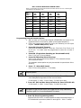
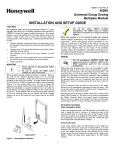
RECOMMENDATIONS FOR PROPER PROTECTION
The Following Recommendations For The Location Of Fire And
Burglary Detection Devices Help Provide Proper Coverage For
The Protected Premises.
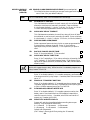
Recommendations For Smoke And Heat Detectors
With regard to the number and placement of smoke/heat detectors, we subscribe to the
recommendations contained in the National Fire Protection Association's (NFPA) Standard #72
noted below.
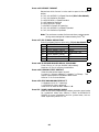
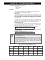
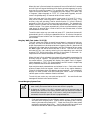
Early warning fire detection is best achieved by the installation of fire detection equipment
in all rooms and areas of the household as follows: For minimum protection a smoke detector
should be installed outside of each separate sleeping area, and on each additional floor of a
multi-floor family living unit, including basements. The installation of smoke detectors in
kitchens, attics (finished or unfinished), or in garages is not normally recommended.
For additional protection the NFPA recommends that you install heat or smoke detectors in
the living room, dining room, bedroom(s), kitchen, hallway(s), attic, furnace room, utility and
storage rooms, basements and attached garages.
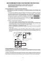
In addition, we recommend the following:
• Install a smoke detector inside every bedroom where a smoker sleeps.
• Install a smoke detector inside every bedroom where someone sleeps with the door partly
or completely closed. Smoke could be blocked by the closed door. Also, an alarm in the
hallway outside may not wake up the sleeper if the door is closed.
• Install a smoke detector inside bedrooms where electrical appliances (such as portable
heaters, air conditioners or humidifiers) are used.
• Install a smoke detector at both ends of a hallway if the hallway is more than 40 feet (12
meters) long.
• Install smoke detectors in any room where an alarm control is located, or in any room
where alarm control connections to an AC source or phone lines are made. If detectors are
not so located, a fire within the room could prevent the control from reporting a fire or an
intrusion.
✪
KITCHEN
▲
DINING
✪
✪
✪
BEDROOM BEDROOM
TV ROOM
▲
KITCHEN
✪
DINING
LIVING ROOM
■
■
✪
✪
LIVING ROOM
BEDROOM
■
✪
✪
BDRM
BDRM
✪
BEDROOM
✪
▲
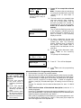
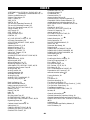
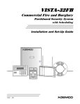
■ Smoke Detectors for Minimum Protection
✪ Smoke Detectors for Additional Protection
▲ Heat-Activated Detectors
■
BEDROOM
✪
■
✪
BEDROOM
TO
BR
BEDROOM
■
▲
▲
KTCHN
.
LVNG RM
■
CLOSED
DOOR
GARAGE
BASEMENT
Recommendations For Proper Intrusion Protection
For proper intrusion coverage, sensors should be located at every possible point of entry to a home or
commercial premises. This would include any skylights that may be present, and the upper windows
in a multi-level building.
In addition, we recommend that radio backup be used in a security system so that alarm signals can
still be sent to the alarm monitoring station in the event that the telephone lines are out of order
(alarm signals are normally sent over the phone lines, if connected to an alarm monitoring station).
–2–
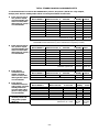
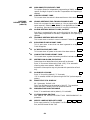
TABLE OF CONTENTS
Section 1.
Section 2.
GENERAL DESCRIPTION ............................................................................................. 8
INSTALLING THE CONTROL ..................................................................................... 10
Mounting the Cabinet ........................................................................................................................ 10
Grade A Mercantile Premises Listing ............................................................................................... 10
Grade A Mercantile Safe & Vault Listing ........................................................................................ 11
Installing the Lock ............................................................................................................................. 11
Installing the Control's Circuit Board .............................................................................................. 11
Telephone Line Connections .............................................................................................................. 12
Connecting the AC Transformer and Backup Battery ..................................................................... 13
Earth Ground Connections ................................................................................................................ 13
Section 3.
INSTALLING REMOTE KEYPADS............................................................................. 14
Keypads That May Be Used .............................................................................................................. 14
Wiring To The Keypads ..................................................................................................................... 14
Mounting The Keypads ...................................................................................................................... 15
Preliminary Check-Out Procedure .................................................................................................... 15
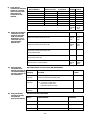
Section 4.
MECHANICS OF PROGRAMMING ............................................................................ 17
General Programming Information .................................................................................................. 17
Entering Program Mode .................................................................................................................... 17
Programming a Data Field ................................................................................................................ 17
Reviewing a Data Field ...................................................................................................................... 18
Erasing an Entry in a Data Field ...................................................................................................... 18
Interactive Mode Programming (✱ 56 and ✱ 82) ............................................................................... 18
Loading Factory Defaults .................................................................................................................. 18
Exiting the Programming Mode ........................................................................................................ 18
Section 5.
BASIC HARD-WIRED ZONES 1–5............................................................................... 19
General Information About Hard-Wired Zones ................................................................................ 19
Wiring Burglary and Panic Devices to Zones 1–5 ............................................................................ 19
Wiring 4-Wire Smoke/Combustion Detectors on Zones 1–5 ............................................................ 19
Zone 4 Tamper Configuration ............................................................................................................ 20
Wiring 2-Wire Smoke Detectors to Zone 5 ........................................................................................ 20
Turning Off Fire Alarm Sounding ..................................................................................................... 21
Programming Hard-Wired Zones ...................................................................................................... 21
Check-Out Procedure for Hard-Wired Zones .................................................................................... 23
Section 6.
SYSTEM ZONES ............................................................................................................. 24
General Information .......................................................................................................................... 24
System Zone Assignments ................................................................................................................. 24
Section 7.
ALARM INDICATING DEVICES ................................................................................ 25
General Information .......................................................................................................................... 25
Connecting Alarm Indicating Devices .............................................................................................. 25
Compatible Alarm Indicating Devices .............................................................................................. 26
Programming External Sounder Options ......................................................................................... 27
Section 8:
AUXILIARY RELAY CONNECTIONS ........................................................................ 28
General Information .......................................................................................................................... 28
Relay Connections .............................................................................................................................. 28
Programming the Auxiliary Relay .................................................................................................... 29
Section 9.
FINAL POWER UP ......................................................................................................... 30
AC Power Connections ....................................................................................................................... 30
Earth Ground Connections ................................................................................................................ 30
Powering Up the System .................................................................................................................... 31
Connecting the Back-Up Battery ...................................................................................................... 31
Calculating the Battery Size Needed ................................................................................................ 31
Total Standby/Alarm Load Worksheets ............................................................................................ 32
Making the Battery Connections ...................................................................................................... 35
Battery Supervision ............................................................................................................ ............... 35
–3–
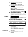
Section 10. ALPHA DESCRIPTION PROGRAMMING ................................................................ 36
Assigning Zone Descriptors ............................................................................................................... 36
Entering Zone Descriptors (in program Menu Mode ✱ 82) .............................................................. 36
Programming the Descriptors ........................................................................................................... 36
Alternate Method for Programming Zone Descriptors .................................................................... 38
Adding Custom Words ............................................................................................................ ........... 39
Alpha Vocabulary List (For Entering Zone Descriptors) ................................................................. 40
Character (ASCII) Chart .................................................................................................................... 41
Section 11. SYSTEM COMMUNICATION ...................................................................................... 42
General Information .......................................................................................................................... 42
Report Code Formats ......................................................................................................................... 42
Table of Contact ID Codes ...................................................................................................... ........... 44
Programming Communication Options ............................................................................................ 45
Section 12. ZONE RESPONSE TYPE DEFINITIONS................................................................... 50
Section 13. DATA FIELD DESCRIPTIONS .................................................................................... 53
Description of System Data Fields .................................................................................................... 53
Section 14. REMOTE PROGRAMMING AND CONTROL (DOWNLOADING) ........................ 61
General Information .......................................................................................................................... 61
Equipment Required .......................................................................................................................... 61
Initial Download ................................................................................................................................. 61
Remote Programming Information ................................................................................................... 62
Remote Programming Advisory Notes .............................................................................................. 62
Section 15. SYSTEM OPERATION ................................................................................................... 63
User Codes .......................................................................................................................................... 63
Master Code ........................................................................................................................................ 63
Secondary User Codes ........................................................................................................................ 63
Keypad Functions .............................................................................................................................. 64
Arming Functions .............................................................................................................................. 64
Panic Keys .......................................................................................................................................... 65
Section 16. TESTING THE SYSTEM................................................................................................ 66
Battery Test ........................................................................................................................................ 66
Dialer Test .......................................................................................................................................... 66
Fire Drill Test ..................................................................................................................................... 66
One Man Fire Walk Test .................................................................................................................... 66
Burglary Walk Test ............................................................................................................................ 67
Armed Burglary Test ............................................................................................................ ............. 67
Trouble Conditions ............................................................................................................................. 68
General Information .......................................................................................................................... 68
"Check" and "Battery" Displays ........................................................................................................ 68
Telephone Line Failure ...................................................................................................................... 68
Power Failure ..................................................................................................................................... 68
Other Displays (Fixed Word Keypads) .............................................................................................. 68
Turning the System Over to the User ............................................................................................... 69
To the Installer ................................................................................................................................... 69
Section 17. TROUBLESHOOTING GUIDE ..................................................................................... 70
Contacting Technical Support In The Event Of Problems .............................................................. 71
Section 18. SPECIFICATIONS & ACCESSORIES ........................................................................ 72
Specifications ..................................................................................................................... 72
Accessories (Compatible Devices) ..................................................................................... 73
SUMMARY OF SYSTEM COMMANDS ....................................................................... 75
REGULATORY AGENCY STATEMENTS .................................................................. 76
LIMITATIONS OF THIS ALARM SYSTEM ............................................................... 78
LIMITED WARRANTY ................................................................................................... 79
INDEX ............................................................................................................................... 80
5120XM SUMMARY OF CONNECTIONS DIAGRAM .................... Inside Back Cover
PROGRAMMING FORM ................................................................................. Centerfold
–4–
LIST OF FIGURES
Figure 1: Cabinet Attack Resistance Considerations ........................................ 10
Figure 2. Installing the Cabinet Lock................................................................. 11
Figure 3. Mounting The PC Board ................................................................ ..... 12
Figure 4. 4-Wire Smoke Detector Connections (Zones 1–5) .............................. 20
Figure 5. 2-Wire Smoke Detector Connected to Zone 5 ..................................... 21
Figure 6. Making Bell Circuit Connections Using Input and Output B of the
PS24 Power Supply Module................................................................ 25
Figure 7. Wiring the Auxiliary Relay Output for Burglary Alarm Devices ..... 28
Figure 8. Wiring the Auxiliary Relay Output for 4-Wire Smoke Detector
Power Usage ........................................................................................ 28
Ademco 5120XM Summary of Connections Diagram ............... Inside Back Cover
–5–
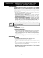
HOW TO USE THIS MANUAL
This manual is written to accommodate both the new and the experienced installer of
Ademco products. A general description of the entire system is located at the
beginning of the manual. The wiring and physical setup of the hardware follows.
The sections at the core of the manual include both hardware setup and
programming requirements of each device to make that specific device operational in
the system. A checkout procedure is included at the end of each section. We
recommend this method to ensure that each device is working properly before
proceeding to the next section. It must also be used if you are making a particular
addition to the system of one of these devices.
Each of the sections covering the installation of peripheral devices includes the
programming for that device. Without an understanding of the programming
methodology, you will not be able to successfully perform the required programming
in each of these sections. We therefore urge you to read Section 4: MECHANICS OF
PROGRAMMING before any programming is performed.
If you are an experienced user of Ademco products, you may choose to wire and then
program the entire system at once. If so, refer to Section 4: MECHANICS OF
PROGRAMMING and Section 13: DATA FIELD DESCRIPTIONS after the hardware
setup is complete. A blank pull-out programming form is included with this manual.
This manual uses various icons to denote critical notes and technical tips to assist
you with the installation of this system. These are easily seen in the left-hand column
of the relevant information.
–6–
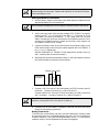
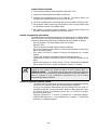
CONVENTIONS USED IN THIS MANUAL
MAIN SECTION TITLES ARE SHOWN IN REVERSE TYPE
Before you begin using this manual, it is important that you understand the
meaning of the following symbols (icons).
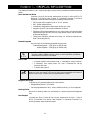
UL
These notes include specific information which must be followed if you are
installing this system for a UL Listed application.
These notes include information that you should be aware of before
continuing with the installation, and which, if not observed, could result in
operational difficulties.
This symbol indicates a critical note that could seriously affect the operation
of the system, or could cause damage to the system. Please read each warning
carefully. This symbol also denotes warnings about physical harm to the
installer.
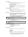
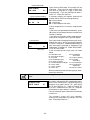
Enter Zn Num.
(00 = Quit)
Many system options are programmed in an
interactive mode by responding to Alpha keypad
display prompts. These prompts are shown in a
double-line box.
01
✱00
When programming the system, data fields are
indicated by a “star” (✱ ) followed by the data field
number.
PRODUCT MODEL NUMBERS: Unless noted otherwise, references to
specific model numbers represent Ademco products.
–7–
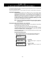
Section 1. GENERAL DESCRIPTION
The Ademco 5120XM is a UL listed fire/burglary control which provides the features outlined
below.
Basic Hardwired Zones
Provides 5 style B (for further explanation of style B, refer to NFPA 72
National Fire Alarm Code Chapter 3: Protected Premises Fire Alarm
Systems) hardwired zones having the following characteristics:
• EOLR supervision supporting N.O. or N.C. sensors
• 300 – 500ms response time
• Individually assignable to bell output and/or aux. relay
• Supports up to 16 2-wire smoke detectors on Zone 5
• Supports 4-wire smoke detectors on any zone (power to these should be
supplied from the control's auxiliary relay power output; see the section
on Hardwired Zones)
• Tolerance of 300-ohm resistance on zones 1-4, 100-ohm resistance on
zone 5 (excluding EOLR)
Remote Keypads
Up to 4 of any of the following keypads may be used :
Fixed-Word Keypads: 6137 (gray) or 6137R (red)
Alpha Keypads: 6139 (gray) or 6139R (red)
A 6139 or 6139R keypad must be used to for keypad programming.
However, these keypads need not remain in the installation provided at
least one 6137 or 6137R is installed.
User Codes
•
•
•
1 Master code for entire system (user 1– intended for use by installer)
5 secondary user codes (users 2–6; user 2 intended for use by
principle end user)
1 duress code (user 8)
Duress Code: An emergency code which, when entered by any user to
disarm or arm the system, will send a silent duress message to the central
station (useful only if report code is programmed for Zone 8).
Keypad Panic Keys
Provides up to 3 programmable panic key functions:
• Designated as Zones 7, 95, and 96
• Can be programmed for 24-hr. silent, audible, auxiliary, or fire responses
Backup Dialer
Has built-in backup dialer for connecting to a second supervised telephone
line.
Bell Outputs
Provides one Style Y (class B) (for further explanation of style Y, refer to
NFPA 72 National Fire Alarm Code Chapter 3: Protected Premises Fire
Alarm Systems), supervised bell output.
–8–
Auxiliary Relay
Provides a built-in 12V wet or dry (jumper selectable) "Form C" relay which
can be used for one of the following:
•
•
•
•
Alarm activation on selected zones, silenced by Code + Off
Trouble/Supervisory activation
4-wire smoke detector reset
Battery saving feature (disconnects power from non-critical loads 4 hours
after AC power loss)
• Alarm activation on selected zones, silenced by Code + #67 (can be used
for elevator recall)
24-Volt Power Supply
Includes the PS24 Power Supply Module, which:
• Supplies two 24VDC, 1.7A full-wave rectified, unfiltered outputs, to be
used as follows:
• One is used to power alarm notification appliances (sirens, strobes, etc.)
• One is used to power 24V auxiliary devices (optional)
Programming
Programmed options are stored in electrically erasable, non-volatile
EEROM memory (information can be reprogrammed at any time and will
not be lost in the event of a power loss). The system can be programmed
by one of the following methods:
• Uploaded, downloaded, or controlled via an IBM compatible computer,
V-Link software and a HAYES modem specified by Ademco
• Programmed through an alpha keypad (6139, 6139R)
UL
Remote programming may only be used when a service technician is at the
site during downloading.
Keypad programming consists of:
• Data field programming
• Interactive (menu) mode programming
A 6139 or 6139R keypad must be used to for keypad programming. However,
these keypads need not remain in the installation provided at least one 6137
or 6137R is installed.
Communication Formats Supported
• Ademco Low Speed (Standard or Expanded)
• Sescoa/Radionics (Standard or Expanded)
• Ademco Express
• Ademco Contact ID
Agency Listings
Fire:
• UL864-NFPA 72 Local, Central Station and Remote Station fire alarm
service
• FM Pending
• CSFM Pending
Burglary:
• UL609 Grade A Local Mercantile Premises and Mercantile Safe and
Vault
• UL611/UL1610 Grade B Central Station Burglary Alarm Service
(Grade A service will be available with future 7720PLUS LORRA)
• UL365 Grade A Police Connect Burglary Alarm Service
–9–
Section 2. INSTALLING THE CONTROL
This section provides instructions for mounting the control cabinet, and installing the cabinet
lock. Also included in this section are instructions for the following:
• Installing the main PC board
• Making phone line connections
• Installing the back-up battery in the cabinet
• Connecting the AC transformer and battery
• Making earth ground connections
Mounting the Cabinet
Mount the control cabinet to a sturdy wall using fasteners or anchors (not
supplied), in a clean, dry area that is not readily accessible to the general
public. Four mounting holes are provided at the back of the cabinet.
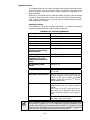
Grade A Mercantile Premises Listing
• The panel door must be supervised. Mount the clip-on tamper switch
(supplied) to the cabinet's right side wall as shown in the diagram below
and wire it to zone 4.
• Use a burglary bell with a tamper protected housing such as the Ademco
AB12. The bell housing's tamper switch and inner tamper linings must
also be wired to zone 4.
Burglary alarm bells should be powered from the control's auxiliary relay
power output.
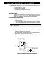
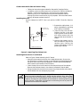
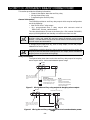
CABINET ATTACK RESISTANCE CONSIDERATIONS
(Shows typical local Grade A listing installation)
PLUG THIS
KNOCK-OUT
PLUG THIS
KNOCK-OUT
CLIP-ON DOOR
TAMPER SWITCH
▲
C-COM
PCB
▲
RUN BELL WIRES
IN CONDUIT
1
1
CABINET
MOUNTING HOLE
(4 PLACES)
PLUG THIS
KNOCK-OUT
TO PLUG AN UNUSED KNOCKOUT OPENING, REMOVE KNOCKOUT AND
INSTALL A PAIR OF DISC PLUGS AND A CARRIAGE BOLT AS SHOWN:
DISC PLUGS (DIMPLES IN DISC
PLUG SHOULD REGISTER INSIDE
KNOCK-OUT OPENING
▲
▲
RUN ALL REMAINING
WIRES THRU HERE
CARRIAGE BOLT
▲
PLUG THIS
KNOCK-OUT
KNOCK-OUT
OPENING
▲
▲
▲
HEX NUT AND
LOCK WASHER
▲
•
▲
•
▲
•
▲
•
Program zone 4 for day trouble/night alarm (type 5, field *56) response
and enable the zone 4 alternate tamper function (field *36).
All wiring between the bell and panel must be run in conduit. Remaining
wires do not need to be run in conduit.
All wiring which is not run in conduit must exit from the knock-out
openings on the bottom or back of the cabinet.
All unused knockouts must be plugged using the disc plugs and carriage
bolts, supplied, as indicated in the diagram below
Fasten the cabinet door to the cabinet backbox using the 18 one inch long
Philips head screws (supplied) after all wiring, programming and
checkout procedures have been completed
▲
•
CABINET SIDEWALL
(OUTSIDE)
Figure 1: Cabinet Attack Resistance Considerations
–10–
Grade A Mercantile Safe and Vault Listing
• Follow the instructions given above for Mercantile Premises listing,.
• In addition, mount a shock sensor such as Sentrol No. 5402 to the panel’s
backbox. Follow the manufacturer's instructions for proper sensor
mounting. Also, a UL listed contact must be used inside the cabinet
through one of the knock-outs for pry-off purposes. Wire the shock sensor
and pry-off tamper contact to zone 4.
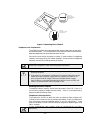
Installing the Lock
Use an Ademco No. N6277 Cam Lock and No. N3422-2 Push-On Retainer
Clip.
RETAINER CLIP
(NOTE POSITION)
LOCKED
RETAINER
CLIP
RETAINER
SLOTS
UNLOCKED
CABINET DOOR BOTTOM
1. Remove the cabinet door. It is
easily removable for servicing
and is easily re-installed.
2. Insert the key into the lock.
Position the lock in the hole
making certain that the latch
will make contact with the
latch bracket when the door is
closed.
3. Hold the lock steady, and insert the retainer clip into the
retainer slots. Position the
clip as illustrated in order to
permit easy removal.
Figure 2: Installing The Cabinet Lock
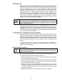
Installing the Control's Circuit Board
Refer to Figure 3 when mounting the PC board.
• Hang the three mounting clips on the raised cabinet tabs. Be sure the
clip orientation is exactly as shown in the diagram to avoid damage to the
clip when mounting screws are tightened. This will also avoid problems
with insertion and removal of the PC board.
• Insert the top of the circuit board into the slots at the top of the cabinet.
Be sure that the board rests in the slots as indicated in step A detail.
• Swing the base of the board into the mounting clips and secure the board
to the cabinet with the accompanying screws.
Be sure that the mounting screws are tight. This ensures that there is a good
ground connection between the PC board and the cabinet. Also, dress field
wiring away from the microprocessor (center) section of the PC board. Use the
2 loops on the left and right sidewalls of the cabinet for anchoring field wiring
using tie wraps. These steps are important to minimizing the risk of panel RF
interference with television reception.
–11–
DETAIL A
SIDE VIEW OF
BOARD INSERTED
INTO SLOTS
DETAIL B
SIDE VIEW OF SHORT
MOUNTING CLIPS
Figure 3. Mounting The PC Board
Telephone Line Connections
The 5120XM provides two supervised dialer outputs referred to as the main
and backup dialers. In fire installations, both outputs must be connected to
separate telephone lines providing loop start service.
Connect the main dialer and back-up dialer (if used) outputs to telephone
company lines using the RJ31X cables supplied. Do not connect to telephone
company lines which provide ground start service.
DO NOT connect both outputs to the same telephone line. A secondary
phone line is required in case of primary phone line failure.
1. To prevent the risk of shock, disconnect phone lines at telco jack before
servicing the panel.
2. If the control is connected to a telephone line inside a PABX, be sure the
PABX has a back-up power supply that can support the PABX for 24
hours (Central Station usage) or 60 hours (Remote Station usage).
Many PABXs are not power backed and connection to such a PABX will
result in a communication failure if power is lost.
Enabling the Dialer Outputs
To enable the dialer outputs, entries must be made in field *79. Enter 1 in
the first entry space to enable the main dialer. Enter 1 in the second entry
space to enable the backup dialer.
Telephone Line Supervision
The supervision circuits on both the main and backup dialer outputs will
indicate a fault when the tip/ring voltage falls below 2 volts, provided that
their supervisory zones are enabled (zones 11 and 12, respectively). These
zones are enabled in field *56 and should be assigned a response type of 19
(24-hr. trouble).
In fire installations, both outputs must be configured for line fault
supervision.
–12–
Dialer Operation
When only the main dialer is enabled ([1,0] in field *79), the 5120XM will
attempt to route all calls over the main output. When both main and back-up
dialers are enabled ([1,1] in field *79), the 5120XM will attempt to route all
calls over the main output until a fault is detected, at which time it will
attempt to use the back-up output. Line faults will result in a Zone 11 MAIN
DIALER FAULT or a Zone 12 BACKUP DIALER FAULT display. The
control will make up to 5 attempts to transmit a report to the primary
number and 5 attempts to the secondary if both numbers are programmed. If
only the primary number is programmed, the control will make 10 attempts
to that number. After the tenth attempt, the control will hang up and a
COMM FAIL will be displayed at the keypad.
The system will not switch to the back-up dialer unless it detects a fault (less
than 2 volts) on the main telephone line. This means that if a report does not
go through on the main phone line due to a programming error, the back-up
dialer will not be activated.
The 5120XM will transmit reports in the following order: alarms (fire,
medical/panic, burglary), fire supervisories and troubles, remaining types of
messages. See the SYSTEM COMMUNICATION section for a description of
communication formats, the types of messages transmitted by the panel, and
for the dialer programming defaults.
Connecting the AC Transformer and Backup Battery
Due to the nature of this product, the transformer must be hardwired into the
premises electrical system. Therefore, we recommend wiring all zones and
expansion modules according to each section's instructions before powering up
the system for programming and testing. Refer to Section 9: FINAL POWER
UP for specific instructions on how to connect the AC transformer and
battery.
If desired, you can wire, program, and test each section individually by
temporarily powering up the control for programming and testing each
section before final power up.
Earth Ground Connections
The 5120XM requires connection to a good earth ground in order to provide
proper 120VAC shock hazard protection, lightening transient protection, and
earth ground fault detection.
Refer to the National Electrical Code for proper earth grounding methods.
To make earth ground connections, do the following:
1. Run an earth ground wire into the transformer enclosure via the same
knockout used for 120VAC wiring.
2. Use a wire nut (not supplied) to splice this earth ground wire to the green
flying lead located inside of and bonded to the transformer enclosure.
Push the mated wires into the enclosure.
3. Connect the green flying lead which emerges from the top of the
transformer enclosure to the 5120XM's earth ground terminal (Terminal
8). Make a connection between this terminal and the PS24's earth ground
terminal (Terminal 3).
4. Replace the transformer enclosure cover after wiring is complete.
–13–
Section 3. INSTALLING REMOTE KEYPADS
This section provides the following information:
• A list of keypads that may be used
• Instructions for wiring and mounting the keypads
• A preliminary check-out procedure to ensure that the keypads are
functioning properly in the system
Keypads That May Be Used
• Fixed-Word Displays: 6137, 6137R
• Alpha Displays: 6139, 6139R
1. A 6139 or 6139R keypad must be used for keypad programming. However,
these keypads need not remain in the installation provided at least one
6137 or 6137R is installed.
2. Many municipalities require fire annunciation devices (keypads included)
to be red in color. Check with the authority having jurisdiction before
selecting a keypad color for your installation.
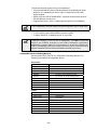
A total of 4 keypads may be used, provided that the 400mA current rating for
Aux. Power #1, Aux. Power #2, and for the system as a whole is not exceeded.
Fixed word and alpha keypads may be used in the same installation.
Multiple keypads may be wired to a single wire run or each may be connected
to a separate wire run back to the control panel using 4-conductor cable.
Follow the maximum wire lengths per gauge defined in the chart below,
taking into consideration the current draw on each wire run.
The total length of all wire runs combined must not exceed 900 feet when
unshielded cable is used (450 ft. if shielded cable is used).
Wire Size
#22
#20
#18
#16
100mA
250 ft.
400 ft.
625 ft.
900 ft.
200mA
125 ft.
200 ft.
310 ft.
450 ft.
300mA
80 ft.
130 ft.
200 ft.
300 ft.
400mA
60 ft.
100 ft.
150 ft.
225 ft.
Example: If you have two keypads on one wire run that draw a total of 200
mA, and you are using #20 AWG wire, the distance from the control panel
Aux + and - terminals to the last device can be up to 200 ft.
Wiring To The Keypads
The 5120XM provides two keypad interface ports. Keypad Port 1 is located
on terminals 17-20 of the terminal block; Keypad Port 2 is located on pins 1,
4, 5, and 7 of the J5 header..
1.
Run field wiring from the control to the keypads (using standard 4conductor twisted wire cable.
If using only one keypad, you may connect it to either Keypad Port 1 or 2, but
it must be mounted on the cabinet or on an electrical box within 3 ft. of the
cabinet with the wiring run in conduit. When using more than one keypad,
you must connect one keypad to Keypad Port 2 and mount it on the cabinet or
on an electrical box within 3 feet of the cabinet with the wiring run in
conduit. Additional keypads can be mounted where desired and connected to
Keypad Port 1 terminals. The keypad on Port 2 is electrically isolated from
those on Port 1 and will continue to function even if wiring problems prevent
the other keypads from working properly.
–14–
2.
3.
Connect the main keypad to Keypad Port 2 as follows, using the 4142TR
cable (supplied):
J5 Header
Keypad Wire
Pin 1
Black (Ground)
Pin 4
Green (Data In)
Pin 5
Red (Aux Power #2 +)
Pin 7
Yellow (Data Out)
Connect remote keypads to the control terminal board as follows:
Terminal Screw
Keypad Wire
17
Red (Aux Power #1 +)
18
Black (Ground)
19
Green (Data In)
20
Yellow (Data Out)
Mounting the Keypads
1. Make sure keypads are set to non-addressable mode (address 31), which
is the factory default setting. If you suspect the address setting is
incorrect (keypads are non-operational), refer to the instructions provided
with the keypad for address setting procedure.
2.
Mount the keypads at a height that is convenient for the user. Refer to
the instructions provided with the keypad for mounting procedure.
You can either surface mount or flush mount 6139(R) keypads (using an
appropriate Trim Ring Kit: 6139TRK). The 6137(R) keypads can be
surface mounted only. Refer to the mounting instructions and template
included with the keypad and/or trim ring kit for specific information.
Preliminary Check-out Procedure
If you want to check that the system is working before connecting field wiring
from zones and devices, do the following:
1. Temporarily connect a 2K-ohm end-of-line resistor across each of the basic
hard-wire zones 1–5, as shown in the Summary of Connections diagram.
Without actual zone wiring or EOL resistors connected, the keypads in the
system will not display the “Ready” message.
2. Power up the system temporarily.
3. B u sy – S tan d by (Alpha keypads) or Not Ready (Fixed-word keypads)
will be displayed.
–15–
After approximately 1 minute*, the green “READY” LED should light,
and Fixed-word keypads should display the word AC. Alpha keypads
should display DISARMED...READY TO ARM (if burglary features are
enabled) or SYSTEM NORMAL (if burglary features are disabled).
* To bypass the 1-minute delay, press # plus 0.
If the “Ready” display does not appear on any of the keypads in the system
or a “Not Ready” message is displayed, check the keypad wiring
connections, and make sure each of the 5 hard-wired zones has a 2K-ohm
resistor connected across its terminals.
4. When you get the proper “Ready” displays on the keypad(s), the system is
functioning properly at this point.
Do not remove the EOL resistors until you are ready to make connections
to the hard-wired zones, to allow for testing later in the installation.
If an OC or OPEN CIRCUIT is present on the keypad, data from the
control is not reaching the keypad. Please check the wiring.
–16–
Section 4. MECHANICS OF PROGRAMMING
This section provides the following information:
• How to enter and exit the programming mode
• How to program a data field
• How to review an entry in a data field
• How to erase an entry in a data field
• How to program user-friendly interactive modes (*56, *82)
• Loading factory defaults
General Programming Information
Characteristics for each installation are stored in non-removable, electrically
erasable, non-volatile EEROM memory. These must be programmed for the
particular installation to establish its specific alarm and reporting features.
It is possible to program the system at any time, even at the installer's
premises prior to the actual installation. Simply apply power temporarily to
the control and then program the unit as desired.
There are two programming modes: data field programming and interactive
(menu) mode programming. Data field programming is used for setting
various system options and interactive programming is used for programming
zone information.
A 6139 or 6139R keypad must be used to for keypad programming.
However, these keypads need not remain in the installation provided at
least one 6137 or 6137R is installed.
Programming can also be performed remotely from the installer’s office/home,
using an IBM personal computer, a modem, and V-Link downloading
software. See the REMOTE PROGRAMMING AND CONTROL
(DOWNLOADING) section.
Entering Program Mode
You may use one of the following methods:
a) Press both the [✱] and [#] keys at the same time within 50 seconds
after power is applied to the Control, or
b) After power up, enter the Master code (5 1 2 0) + 8 0.
This method is disabled if you exit the program mode using ✱98 instead of
✱99. See “Exiting Program Mode” paragraph later in this section.
If a different Master code is subsequently programmed, use it instead of
5120 to gain access to the Programming mode.
Following entry into program mode, data field ✱20 will be displayed (this is
the first field in the system). The system will now accept entries for field ✱ 20.
Programming a Data Field
1. Press [ ✱] plus Field No. (for example, ✱21); then make the required entry.
2. When you have completely programmed a data field, the keypad will
“beep” three times and then automatically display the next data field in
sequence. To go to a different field, press [✱] plus the desired field No.
3. If the number of digits that you need to enter in a data field is less than
the maximum digits available (for example, the phone number field), enter
the desired data, then press ✱ and the next data field number to be
programmed.
4. If you try to enter a non-existent field, the keypad will display EE or
Entry Error. Simply re-enter [✱ ] plus a valid field number.
–17–
Reviewing a Data Field
Press [#] plus Field No. Data will be displayed for that field number. No
changes will be accepted in this mode.
Erasing an Entry in a Data Field
To delete an entry in a field, press [ ✱] plus Field No. + [✱]. (Applies only to
fields ✱40– ✱43, and ✱94).
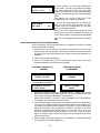
Interactive Mode Programming ( ✱56 and ✱82)
Typical prompt displayed
during interactive mode
programming
Press [ ✱] plus interactive mode No. (for
example, ✱ 56). The Alpha keypad will display the
first of a series of prompts requesting entries.
Make entries, and then press * to continue. To
back up one screen, press the # key.
A detailed procedure (with displays of prompts) is
provided in those sections where programming in
the interactive mode is to be performed.
Enter Zn Num.
(00 = Quit) 01
Zone Number ↑
Interactive Mode
✱56 Zone Programming
✱82
Alpha Programming
Used To Program
Zone characteristics, report codes, and alpha
descriptors.
Zone alpha descriptors
Loading Factory Defaults
To load the factory defaults, enter the programming mode, press
then exit the programming mode.
✱97,
and
Do not press ✱97 to load defaults if any programming has been done
previously—data already programmed into the system will be changed!
✱96
resets the Subscriber Account number and CSID in preparation for an
initial download. If using this, this must be done after *97 if loading factory
defaults.
Exiting the Programming Mode
✱99 allows re-entry into the program mode using Master Code + 8 0.
✱98 inhibits re-entry into the programming mode using the Master code.
–18–
Section 5. BASIC HARD-WIRED ZONES 1–5
This section provides the following information:
• General information about hardwired zones
• Installing 2-wire smoke detectors
• Installing 4-wire smoke/combustion detectors
• Programming hardwired zones
• Checkout procedure for hardwired zones
General Information about Hardwired Zones
Provides 5 Style B supervised hardwired zones having the following
characteristics:
• EOLR supervision supporting N.O. or N.C. sensors, including:
– fire alarm sensors (N.O. only)
– 24-hr. alarm sensors
– burglary sensors
– fire sprinkler supervisory sensors
• 300 – 500ms response time
• Individually assignable to bell output and/or aux. relay
• Supports up to 16 2-wire smoke detectors on Zone 5
• Supports 4-wire smoke detectors on any zone (power to these should be
supplied from the system's auxiliary relay power output; see Installing 4Wire Smoke Detectors later in this section).
• Tolerance of 300-ohms on Zones 1-4, 100-ohms on Zone 5 (excluding
EOLR)
Use the model #610-7 2k EOLR's (supplied) on zones programmed for fire
alarm or fire supervisory response. Use the standard 2k EOLRs (supplied) on
zones programmed for panic and burglary alarm responses.
Wiring Burglary and Panic Devices To Zones 1– 5
1. Connect sensors/contacts to the hardwired zone terminals (see the
Summary of Connections diagram).
2. Connect closed circuit devices in series on the high (+) side the loop. The
EOL resistor must be connected in series with the devices, following the
last device (see the Summary of Connections diagram).
3. Connect open circuit devices in parallel across the loop. The 2K-ohm EOLR
must be connected across the loop wires at the last device.
If the EOLR is not at the end of the loop, the zone will not be properly
supervised, and the system may not respond to an open circuit on the zone.
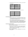
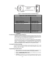
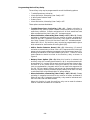
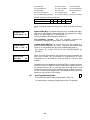
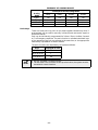
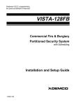
Wiring 4-Wire Smoke/Combustion Detectors on Zones 1-5
The system will support as many 4-wire detectors as can be powered from
Auxiliary Relay Power on Zones 1-5. Refer to the detector’s instructions for
complete details regarding its proper installation and operation.
1. Connect 12-volt power for the detectors from the Auxiliary Relay Output,
(which can be programmed to interrupt power for fire alarm reset).
Observe proper polarity when connecting detectors.
2. Connect detectors (including heat detectors, if used) across terminals of
the zone selected. All detectors must be wired in parallel.
–19–
Remove the 2000 ohm EOL resistor if connected across the zone terminals,
and connect it across the loop wires at the last detector.
3. Power to the smoke detectors must be supervised in fire
installations. To supervise power, we recommend the use of a System
Sensor No. A77-716B supervisory module.
7
POWER
TO
DETECTORS 18
+
-
+
UL LISTED
COMPATIBLE
CONTROL
PANEL
4-WIRE SMOKE
DETECTORS
-
+
•
•
-
EOL
POWER
SUPERVISION
RELAY
MODULE
A77-716B
•
•
ZONE
TERMINALS
+
+
2000Ω
EOLR
HEAT
DETECTOR
Four-Wire Detector Circuit
Figure 4: 4-Wire Smoke Detector Connections (Zones 1-5).
COMPATIBLE 4-WIRE SMOKE/COMBUSTION DETECTORS
1412
System Sensor, 4-wire ionization products of combustion
detector
2412
System Sensor, 4-wire photoelectric smoke detector
2412TH
System Sensor, 4-wire photoelectric smoke detector
w/135º F (57º C) heat detector
2112/24T
System Sensor low-profile 4-wire photoelectric smoke
detector w/135º F (57º C) heat detector
Zone 4 Tamper Configuration
Zone 4 may be used as a tamper loop for the 5120XM cabinet door tamper
switch and for the Ademco AB12 Grade A burglary bell box tamper switches
and tamper liner. To program Zone 4 as a tamper, set program field *36 to
"1" and program Zone 4 for zone response type 5 (Trouble-by-Day/Alarm-byNight).
When set in this manner, the zone will trigger a trouble when the panel is
disarmed and an alarm when the panel is armed, when the zone senses either
an open or a short, or when an earth ground fault caused by drilling through
the AB12 housing is detected. See the section on EXTERNAL SOUNDERS
for information on AB12 bell wiring.
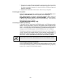
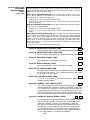
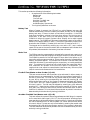
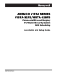
Wiring 2-Wire Smoke Detectors To Zone 5
1. Connect up to 16 2-wire smoke detectors across Zone 5 terminals (2mA
standby current available). Observe proper polarity when connecting the
detectors.
Due to the alarm current available on zone 5, only one smoke detector at a
time can be supported in the alarmed state.
2. If an EOL resistor is presently connected across zone 1 terminals, remove
it. The EOL resistor must be connected across the loop wires at
the last detector.
3. See “Programming Hard-Wired Zones” later in this section for a detailed
programming procedure.
–20–
@@@@@@@@e?@@@@@@@@e?@@@@@@@@?e@@@@@@@@e?@@@@@@@@?e@@@@@@@@e?@@@@@@@@?e@@@@@@@@e?@@@@@@@@?e@@@@@@@@e?@@@@@@@@?e@@@@@@@@
@@@@@@@@e?@@@@@@@@e?@@@@@@@@?e@@@@@@@@e?@@@@@@@@?e@@@@@@@@e?@@@@@@@@?e@@@@@@@@e?@@@@@@@@?e@@@@@@@@e?@@@@@@@@?e@@@@@@@@
@@
@@h?
@@
@@h?
@@
@@h?
@@
@@h?
@@
@@h?
@@
@@h?
@@
@@
@@
@@
@@
@@
@@
@@
@@
@@
@@
@@
@@
@@
@@
@@
@@
@@
@@
@@
@@
@@
@@
@@
@@
@@
@@
@@
@@
@@
@@
@@
@@
@@
@@
@@
@@
@@
@@
@@
@@
@@
@@
@@
@@
@@
@@
@@
@@
@@
@@
@@
@@
@@
@@
@@
@@
@@
@@
@@
@@
@@
@@
@@
@@
@@
@@
@@
@@
@@
@@
@@
@@
@@
@@
@@
@@
@@
@@
@@
@@
@@
@@
@@
@@
@@
@@
@@
@@
@@
@@
@@
@@
@@
@@
@@
@@
@@
@@
@@
@@
@@
@@
@@
(-)
@@
@@
@@
@@
@@
@@
@@
@@
@@
@@
@@
@@
@@
@@
@@
@@
@@
@@
@@
@@
@@
@@
@@
@@
@@
@@
@@
@@
@@
@@
@@
@@
@@
@@
@@
@@
@@
@@
@@
@@
2 WIRE SMOKE
DETECTOR
16
@@
@@
@@
@@
@@
@@
@@
@@
@@
@@
@@
@@
@@
@@
@@
@@
@@
@@
@@
@@
@@
@@
@@
@@
@@g
@@g
@@g
@@g
@@g
@@g
@@@@@@@@
@@@@@@@@
@@
@@
@@
@@
@@
@@
@@
@@
ZONE 1
@@
@@
@@
@@
@@
@@
@@
@@
@@
@@
@@
@@
@@
@@
@@
@@
ZONE 5
2K
EOLR
@@
@@
@@
@@
@@
@@
@@
@@
SMOKE
@@
@@
@@
@@
@@
@@
@@
@@
@@
@@
@@
@@
@@
@@
@@
@@
15
(+)
@@
@@
@@
@@
@@
@@
@@
@@
?@@@@@@@@?e@@@@@@@@e?@@@@@@@@?e@@@@@@@@e?@@@@@@@@?e@@@@@@@@e?@@@@@@@@?e@@@@@@@@e?@@@@@@@@?e@@@@@@@@
?@@@@@@@@?e@@@@@@@@e?@@@@@@@@?e@@@@@@@@e?@@@@@@@@?e@@@@@@@@e?@@@@@@@@?e@@@@@@@@e?@@@@@@@@?e@@@@@@@@
?@@
?@@
?@@
?@@
?@@
?@@
?@@@@@@@@
?@@@@@@@@
Figure 5: 2-Wire Smoke Detector Connected to Zone 5
COMPATIBLE 2-WIRE SMOKE DETECTORS
Detector Type
Device Model #
Ionization, direct wire
System Sensor 1100
Ionization with B110LP base
System Sensor 1151
Ionization, direct wire
System Sensor 1400
Ionization w/B401B base
System Sensor 1451
Ionization duct detect. w/DH400 base
System Sensor 1451DH
Photoelectric, direct wire
System Sensor 2100
Photoelectric w/heat sensor, direct wire
System Sensor 2100T
Photoelectric w/B110LP base
System Sensor 2151
Photoelectric w/heat sensor, direct wire
System Sensor 2300T
Photoelectric, direct wire
System Sensor 2400
Photoelectric w/heat sensor, direct wire
System Sensor 2400TH
Photoelectric w/B401B base
System Sensor 2451
Photoelectric w/heat sensor & B401Bbase
System Sensor 2451TH
Photoelectric duct detector w/DH400 base
System Sensor 2451
Note: Mixing of the above types of smoke detectors on zone 5 is
permitted.
Fire Alarm Verification for Smoke Detectors
This feature applies to 2-wire smoke detectors wired to Zone 5 when set to
response type 16. It also applies to 4-wire smoke detectors wired to any zone
set to response type 16, provided that the detectors are powered from the
auxiliary relay power output (field *34 must be set to "2").
The control panel will “verify” any alarm by resetting the smoke detectors
after the first alarm trigger, and then waiting 90 seconds for a second alarm
trigger. If the smoke detector or thermostat does not trigger again, the
control will disregard the first trigger, and no alarm signal will occur. This
feature eliminates false alarms due to electrical or physical transients.
Turning Off Fire Alarm Sounding
You can turn off fire alarm sounding by entering the [User Code] + OFF on any
keypad. To clear the "memory of alarm" and to reset the detector’s alarm, enter
the [User Code] + OFF again.
Programming Hard-Wired Zones
1.
2.
3.
With at least one 2-line Alpha keypad (6139/6139R) connected to the
keypad terminals on the control, power up the system temporarily.
Enter the programming mode by keying the following on the Alpha
keypad: Master code (5 1 2 0) + 8 0.
Press ✱56. Note that this is an interactive programming mode. You will
use it to program zone numbers, zone types and alarm report codes for
–21–
hard-wired zones.
Enter Zn Num.
(00 = Quit)
01
Zone Number ↑
Typical summary display
Zn ZT
01 09
RC
00
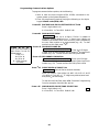
Upon entering ✱ 56 mode, this prompt will be
displayed. Enter the first zone number that
you wish to program (or [0][0] to exit zone
programming). If you are starting with zone 1,
enter “01”. Press ✱ to continue.
A summary display will appear, showing the
present status of that zone's programming.
Zn = zone number;
ZT = zone type;
RC = report code for that zone;
Values displayed are currently programmed
values.
If the zone is programmed satisfactorily, press
[#] to back up one step and enter the next zone
number, if desired.
If you want to change a zone’s programming,
press [ ✱]. A prompt for Zone Type will appear.
↓ Zone Number
01 Zone Type
Fire
09
Zone Type ↑
Each zone must be assigned a zone type, which
defines the way in which the system responds
to faults in that zone. A detailed explanation of
each zone type is provided in “Response Type
Definitions” in Section 12: ZONE RESPONSE
TYPE DEFINITIONS.
Enter the desired zone type code, as listed
below.
00 = Zone Not Used
01 = Entry/Exit Burglary
02 = not used
03 = Perimeter Burglary
04 = Interior, Follower
05 = Trouble Day/Alarm Night
06 = 24 Hr Silent
07 = 24 Hr Audible
08 = 24 Hr Aux
09 = Fire Without
Verification.
10 = Interior w/Delay
16 = Fire With
Verification
17 = Fire Waterflow
18 = Fire Sprinkler
Supervisory
19 = 24-Hr. Trouble
When the display shows the zone type you want,
press [ ✱] to continue.
You must enter “00” as the zone type for any hard-wired zones that are not
used.
01 Report Code
1st 03 2nd 12
3C
The report code consists of 2 hexadecimal digits,
each in turn consisting of 2 numerical digits. For
example, for a report code of "3C", enter [0][3]
for "3" and [1][2] for "C". Refer to Section 11:
SYSTEM COMMUNICATION for complete
information on report codes, if necessary.
Enter the desired report code and then press [✱ ]
to continue.
The summary screen will now reappear,
showing the programming changes for that
zone. Press [ ✱] to continue.
–22–
Program Alpha?
0 = No 1 = Yes
Enter Zn Num.
(00 = Quit)
0
02
Enter next zone number ↑
The next request is to enter Alpha descriptors
for the zones. The entry may be done now (enter
1) or may be done at a later time using ✱ 82
interactive mode (enter 0). We recommend that
the entry of Alpha descriptors be done using ✱ 82
mode.
See Section 10: ALPHA DESCRIPTION
PROGRAMMING for specific procedure.
If “0” (no) was entered above, the system will
return to the "Enter Zone Number" prompt.
Proceed with the programming for the next
zone, as indicated previously.
When you have finished programmed the hardwired zones, exit ✱ 56 interactive mode at the
"Enter Zone Number" prompt by pressing: [0] [0].
Then exit the programming mode by pressing
✱99.
Check-Out Procedure For Hard-Wired Zones
After installation of all hard-wired devices is completed, the security system
should be checked, as follows.
1. Make certain that all devices and sensors connected to the hard-wired
zones are not in a faulted state. Doors and windows with contacts should
be closed, PIRs should be covered (use a cloth to mask them temporarily if
necessary).
2. Power up the system temporarily.
3. After a 50 second delay, with all hard-wired zones intact, the Alpha
keypad connected to the system should display:
(If Burglary features are
enabled)
(If Burglary features
are disabled)
DI SA RM ED
REA DY T O A RM .
SYSTEM
NORMAL
If the following is displayed,
DI SA RM ED P r e ss ✱
to sh o w fa u lts
PRESS * TO SHOW
FAULTS
press the [✱] key to display the faulted zone(s). Restore any faulted
zone(s) as necessary (also make sure that you have connected a 2K-ohm
EOL resistor across the terminals of unused zones).
When the DISARMED...READY TO ARM message or SYSTEM NORMAL
is displayed, you can proceed to the next step.
4. Fault and then restore every contact or sensor on each zone individually to
ensure that it is being monitored by the system. Each time a burglary zone
is faulted, the keypad should display the number of the faulted zone.
When each burglary zone is restored, the READY TO ARM or SYSTEM
NORMAL message should appear again. For fire and 24-hr. zones, this
test may activate external alarm sounders and send a central station
report. Therefore, alert building occupants and the central station before
conducting this test.
5. When you get the proper displays on the keypad(s), the hard-wired zones
in the system are functioning properly.
–23–
Section 6. SYSTEM ZONES
This section provides the following information:
• General information about system zones
• System zone assignments
General Information
System zones may be comprised of the following:
• Zones which monitor various device connections, as well as earth ground
faults
• Keypad panic zones, which may be assigned 24-hr. zone responses that
are activated whether the system is armed or disarmed
• Zones which have a special purpose such as to bypass a relay, or to
assign a zone descriptor to a relay
System Zone Assignments
Zone 6: Bell Supervision – monitors the bell circuit output for open and
short circuit faults. Defaults to zone response type 19 (24-Hr.
Trouble) .
Zone 7: Keypad Panic – activated by pressing the keypad [B] key or by
simultaneously pressing the[*] and [#] keys. Keys must be held for
two seconds.
Zone 8: Keypad Duress – activated by using the duress code (corresponds to
User Code # 8) at the keypad. This generates a call to the central
monitoring station (only useful if a report code is programmed for
Zone 8).
Zone 10: Earth Ground Supervision – monitors the control's field wiring for
earth ground faults. Defaults to zone response type 19 (24-Hr.
Trouble). Supervision must be enabled (response type 19) for fire
installations.
Zone 11: Main Dialer Supervision – monitors the main dialer telephone
connection for line faults. Defaults to zone response type 19 (24-Hr.
Trouble).
Zone 12: Back-up Dialer Supervision – monitors the backup dialer telephone
connection for line faults. Defaults to zone response type 19 (24-Hr.
Trouble).
Zone 13: Auxiliary Relay Disable – represents the auxiliary relay for
purposes of allowing this relay to be bypassed. Does not supervise
anything and does not get assigned a zone response type.
Zone 95: Keypad Panic – activated by pressing the keypad [A] key or by
simultaneously pressing the [1] and [*] keys. Keys must be held for
two seconds.
Zone 96: Keypad Panic – activated by pressing the keypad [C] or by
simultaneously pressing the [3] and [#] keys. The keys must be
held for two seconds to activate the panics.
System zones are programmed through *56 Zone Programming Mode.
The default values for these zones will meet the requirements for most
installations.
–24–
Section 7. ALARM INDICATING DEVICES
This section provides the following information:
• General information about the bell circuit output
• Connecting alarm indicating devices
• Examples of compatible alarm indicating devices
• Using the PS24 Power Supply Module
• Programming external sounder options
General Information
The Ademco 5120XM provides one 12VDC bell circuit output (rated at 1014VDC), which must be connected to the PS24 Power Supply module for
powering 24V alarm indicating devices (horns, bells, sirens, etc.). This output
may be configured for Style Y EOLR supervision or no supervision, and is
intended for use as a supervised fire alarm indicating circuit.
Alarm indicating devices for burglary alarm sounding should be connected to
the auxiliary relay output, as described in the next section.
The total alarm current that can be drawn from 5120XM's bell, auxiliary
relay, auxiliary power output #1, and auxiliary power output #2 outputs
combined must not exceed 1 amp.
The PS24 Power Supply Module provides an additional 1.7A @24VFW (full
wave rectified, unfiltered) current.
Connecting Alarm Indicating Devices
Mount the PS24 module in the 5120XM cabinet as per instructions supplied
with the PS24.
Make connections from alarm output terminals on the control (Terminals 3
and 4) to PS24 Input A Terminals 10(+) and 11(-), or Input B Terminals 15(+)
and 16(-). If Input A is used, Output A must be used to connect alarm
indicating devices; if Input B is used, Output B must be used to connect
alarm indicating devices.
Wire polarized alarm indicating devices to the PS24 Output as shown below.
POLARIZED INDICATING DEVICES
USE EOLR SUPPLIED WITH THE CONTROL
CONNECT TO CONTROL PANEL EOLR SUPERVISED BELL
CIRCUIT RATED 9.5-14 VDC TO CONFIGURE OUTPUT B
AS 24VFW EOLR SUPERVISED BELL CIRCUIT
OUTPUT A RATING: 21 - 30VFW, 1.7 AMPS MAX
(FULL WAVE RECTIFIED, UNFILTERED)
POWER LIMITED
CONNECT TO CONTROL PANEL AUXILIARY POWER
RATED 9.5 - 14 VDC TO CONFIGURE OUTPUT A
AS 24VFW AUXILIARY OUTPUT
{
{
{
▲
2K
EOLR
STROBE
▲
OUTPUT B RATING: 21 - 30VFW, 1.7 AMPS MAX
(FULL WAVE RECTIFIED, UNFILTERED)
POWER LIMITED
BELL
OUTPUT B
(ALARM POLARITY
SHOWN)
WHITE
50 mA CURRENT
DRAW ON ALARM
INPUT B
(ALARM POLARITY
SHOWN)
YEL-
OUTPUT A
50 mA
CURRENT DRAW
ORANGE
INPUT A
GRAY
18
17
16
15
14
13
12
11
10
–
+
–
PS24
MODULE
+
NO
CONNECTION
–
+
–
+
EITHER OUTPUT MAY BE CONFIGURED AS 24VFW
AUXILIARY OUTPUT OR AS 24VFW EOLR SUPERVISED BELL CIRCUIT.
SEE NOTE 3
Figure 6:
Making Bell Circuit Connections Using Input and
Output B of the PS24 Power Supply Module .
–25–
To supervise the bell output wiring, do the following:
• Connect polarized 24V alarm indicating devices in parallel across either
Output A or B (depending on which Input is used) of the PS24 Power
Supply Module.
• Attach a 2K-ohm EOLR (Model #610-7, supplied) across the bell wires at
the last device on the wire run.
• Program Zone 6 for a 24-Hr. trouble response type (this is the default).
In fire installations, the bell output must be configured for EOLR supervision.
To unsupervise the bell output wiring, do the following:
• Cut the white jumper labeled W2 on the control panel.
• Program Zone 6 for a response type of "0" (not used).
The PS24's Low AC and Low Battery outputs must be connected to the
5120XM's Connector J5 pins 8 and 9, respectively, and not to supervised
zones on the 5120XM, as shown in the PS24's Installation Instructions.
Additionally, program field *37 must be set to "1" so that the 5120XM will
read AC and battery power status from the PS24's Low AC and Low Battery
outputs instead of from its internal AC/battery monitoring circuitry.
Compatible Alarm Indicating Devices
Use only polarized 21-30VFW, UL listed alarm indicating devices. The
following are examples of compatible devices.
Horn/Strobes:
System Sensor
MASS2415ADA
System Sensor
MASS2475ADA
System Sensor
MASS24110ADA
System Sensor
MASS241575ADA
Wheelock
MT-24-LS–VFR & MT4-24-LS–VFR
Wheelock
MT-24-LSM –VFR & MT4-24-LSM–VFR
Wheelock
MT-24-MS–VFR & MT4-24-MS–VFR
Wheelock
MT-24-IS–VFR & MT4-24-IS–VFR
Gentex
SHG24–15–1
Gentex
SHG24–1575
Gentex
SHG24–110–1
Strobes:
System Sensor
SS2415ADA
System Sensor
SS241575ADA
System Sensor
SS2475ADA
System Sensor
SS24110ADA
Wheelock
LS1M–24–VFR
Wheelock
MS1–24–VFR
Gentex
GXS–4–15–1
Gentex
GXS–4–1575
Gentex
GXS–4–110–1
–26–
BELL CIRCUIT WIRE RUN LENGTH TABLE
NOTE: Lengths below are measured from PS24 to farthest device on wire run. These lengths
correspond to a voltage drop of 2.4V
Bell
Current
(mA)
#18
AWG
#16
AWG
#14
AWG
#12
AWG
100
1870 ft
2980 ft
4750 ft
7550 ft
250
750 ft
1190 ft
1900 ft
3020 ft
500
375 ft
590 ft
950 ft
1510 ft
750
250 ft
390 ft
630 ft
1000 ft
1000
180 ft
290 ft
470 ft
750 ft
1250
150 ft
230 ft
380 ft
600 ft
1500
120 ft
190 ft
310 ft
500 ft
1700
110 ft
170 ft
270 ft
440 ft
Programming External Sounder Options
1. With at least one 2-line Alpha keypad (6139/6139R)) connected to the
keypad terminals on the control, power up the system temporarily.
2. Enter the programming mode by keying the following on the Alpha
keypad: Master code (5 1 2 0) + 8 0.
3. Press ✱ 30. (Alarm Bell Timeout).
Enter 0 for no timeout (default), 1 for 4 min, 2 for 8 min, 3 for 12 min, or 4
for 16 min. Fire bells must be programmed to sound for at least 5
minutes.
4. Press ✱ 28. (Single Alarm Sounding per Zone/Armed Period).
Enter “1” for yes, “0” for no (default).
5. Press ✱ 76. (Waterflow Alarm Silencing).
Enter “0” for manual silence only (default), “1” for automatic silence
when waterflow ceases.
The automatic silence option may only be used with the permission of the
local AHJ.
6.
Press * 77. (Alarm Bell Sound).
Enter "0" for pulsing (default), "1" for steady.
The pulsing option causes the bell to sound using the NFPA three pulse
temporal pattern.
7.
Press *85. (Bell and Aux. Relay Activation for Zones 1-7).
Enter Relay/Bell assignments for each zone as follows:
0 = No output; 1 = Bell; 2 = Aux. Relay; 3 = Bell & Aux relay
8. Press *86. (Bell and Aux. Relay Activation for Zones 10-12, 95 & 96)
0 = No output; 1 = Bell; 2 = Aux. Relay; 3 = Bell & Aux relay
Zones programmed for fire alarm response (zone types 9, 16, and 17) must be
assigned to trigger the bell output (can trigger the aux. relay additionally).
Therefore, option 1 or 3 must be selected for fire zones.
9. Press *56. (Zone Programming mode).
Program Zone 6 for 24-Hr. trouble response to supervise the bell output, or
"0" to disable bell supervision (default is zone type 19 – 24-Hr. Trouble).
–27–
Section 8: AUXILIARY RELAY CONNECTIONS
This section provides the following information:
• General information about the auxiliary relay
• Wiring the auxiliary relay
• Programming the auxiliary relay
General Information
The 5120XM provides on auxiliary relay output which may be configured as
one of the following:
• Wet 12VDC form C relay output
• Dry, unsupervised form C relay output with contacts rated at
30VAC/VDC, 2A max, resistive loads.
The relay pole (terminal 6) is set at the factory for a 12V nominal (10-14VDC)
output, providing 400mA max standby current/1A max alarm current.
The total combined standby current that can be drawn from the 5120XM's
auxiliary relay, aux. power #1, and aux. power #2 outputs cannot exceed
400mA. The total alarm current that can be drawn from these outputs plus
the bell output cannot exceed 1A.
If configuring the relay as a dry, form C relay output, cut the red jumper
labeled W3 on the PC board.
Installations providing burglary alarm service should use this output for
burglary alarm bell activation (configure as a 12V output, which activates on
burglary alarm and provides arming ding).
Relay Connections
The figures below show how to wire the auxiliary relay output for burglary
alarm output and for 4-wire smoke detector power usage.
ALARM
5
6
7
-
GROUND
+
N.C.
POLE
N.O.
Note: The control provides
12VDC power on terminal 6
when the red jumper (W3) is
intact.
18
AUX RELAY
FACTORY DEFAULTS
• Set for alarm activation (✴34=1)
• No zones trigger by default
(Must program ✴85, ✴86)
• 16 min. timeout(✴31=4)
NOTES:
• Use non-polarized indicating
devices
• Wiring is not supervised
• Take care not to exceed the
terminal 6 and overall system
alarm current ratings.
Figure 7: Wiring the auxiliary relay output for burglary alarm output.
RESET
5
6
TO
HARDWIRED ZONE (ZN 1-5)
7
18
GROUND
N.C.
POLE
-
+
EOLR RELAY
BRK A77-716B
-
N ote: The control provides
12VDC power on terminal 6
4-WIRE
SMOKE
DETECTOR
+
when the red jumper (W3) is
intact.
EOLR
Figure 8: Wiring the auxiliary relay output for 4-wire smoke detector power
usage.
–28–
Programming the Auxiliary Relay
The auxiliary relay may be programmed for one of the following options:
• Trouble/Supervisory Activation
• Alarm Activation, silenced by [User Code] + OFF
• 4-Wire Smoke Detector Reset
• Battery Saver
• Alarm Activation, silenced by [User Code] + # 67
These options are described below:
• Trouble/Supervisory Activation (*34 = 0) : Steady activation in
response to any zone or system related trouble condition or to any fire
supervisory condition. Remains activated until all fault conditions have
been corrected and the User Code + OFF has been entered.
• Alarm Activation, silenced by [User Code] + OFF (*34 = 1): Steady
activation in response to an alarm on one, some or all zones, as selected in
fields *85 and *86. If selected, the auxiliary relay remains activated until
Aux. Relay Timeout (*31) or until the User Code + OFF has been entered.
When field *34 = 1, the auxiliary relay can also be programmed to give a
brief activation for confirmation of arming (field {*35).
• 4-Wire Smoke Detector Reset (*34 = 2): Momentary (6 second)
activation at second entry of User Code + OFF sequence which interrupts
power to 4-wire smoke detectors connected to hard-wired zones (zones 1-5),
allowing the detectors to be reset following an alarm . Power to 4-wire
smoke detectors should be wired to the auxiliary relay as shown in
Figure 8.
• Battery Saver Option (*34 = 3): When this function is selected, the
auxiliary relay will normally be activated (i.e. N.O. and pole contacts will
be connected, N.C. contact will be open) and will de-activate 4 hours after
the start of an AC power failure. Using this feature, non-critical loads
(such as supplementary keypads) which do not need to be supported for
the full 24 hour battery backup period can be disconnected from the
auxiliary outputs, allowing a smaller capacity battery to be used. The relay
re-activates within a few seconds after AC power restores.
• Alarm Activation, silenced by [User Code] + # 67 (*34 = 4): Steady
activation in response to an alarm on one, some or all zones, as selected in
fields *85 and *86. If selected, the auxiliary relay remains activated until
the User Code + #67 has been entered.
When this function is used, the auxiliary relay can be used for elevator
recall or ventilator shutdown on fire alarms.
–29–
Section 9. FINAL POWER UP
This section provides the following information:
•
•
•
•
•
Connecting the AC transformer
Making earth ground connections
Applying power to the control
Installing the backup battery
Backup battery calculations
In Section 2, you made temporary power connections for the purpose of
programming and testing the installation. This section provides information
about final power-up procedures and battery size calculations.
AC Power Connections
The 5120XM has a built-in, enclosed AC power transformer with manually
resettable circuit breaker protection, located in the lower lefthand corner of
the control's cabinet.
UL
1. A dedicated 120VAC circuit must be used for fire applications. Run
120VAC wiring to the control in conduit.
2. Wires must be rated for 90 degrees -C or higher operation.
Follow the steps below to make AC power connections.
1. Remove the cover from the transformer's enclosure.
2. Remove the lower knockout on the lefthand side of the cabinet. Run
120VAC power wires into the transformer enclosure via this knockout.
Make sure that the dedicated AC circuit is not powered at this time.
Apply AC power only after all other wiring, except the backup battery wiring,
has been completed.
3. Use wire nuts (not supplied) to splice the 120VAC wires to the
transformer's black and white flying leads. Push the mated wires back
into the transformer enclosure.
4. Connect the transformer's 18VAC BLUE flying leads which emerge from
the top of the enclosure to the 5120XM's AC terminals (Terminals 1 and 2).
Connect the transformer's 30VAC Yellow flying leads that emerge from the
top of the enclosure to the PS24's AC terminals (Terminals 1 and 2).
Maintain at least 1/4" spacing between the transformer's blue and yellow
wires and other control field wiring. The yellow wires should be tiewrapped to the tie-wrap loop on the cabinet's left side wall when the PS24
will not be used.
5. Connect pin 8 on the J5 header of the 5120XM to Terminal 8 on the PS24
Power Supply for AC power supervision.
6. Make earth ground connections as specified below.
Earth Ground Connections
The 5120XM requires connection to a good earth ground in order to provide
proper 120VAC shock hazard protection, lightening transient protection, and
earth ground fault detection.
Refer to the National Electrical Code for proper earth grounding methods.
To make earth ground connections, do the following:
1. Run an earth ground wire into the transformer enclosure via the same
knockout used for 120VAC wiring.
2. Use a wire nut (not supplied) to splice this earth ground wire to the green
flying lead located inside of and bonded to the transformer enclosure.
Push the mated wires into the enclosure.
–30–
3. Connect the green flying lead which emerges from the top of the
transformer enclosure to the 5120XM's earth ground terminal (Terminal
8). Make a connection between this terminal and the PS24's earth ground
terminal (Terminal 3).
4. Replace the transformer enclosure cover after wiring is complete.
Powering Up the System
Apply AC power to the control. Following power-up, Busy-Standby (Alpha
keypads) or NOT READY (fixed-word keypads) will be displayed.
After approximately 1 minute, the initial displays will revert to
DISARMED...READY TO ARM or SYSTEM NORMAL for Alpha keypads,
or AC for Fixed-word keypads (if there are no faulted zones). This 1-minute
delay allows PIRs, etc. to stabilize.
To bypass this delay, press: [#] + [0].
Connecting The Back-Up Battery
In the event of an AC power loss, the 5120XM control and PS24 power supply
module must be supported by a back-up, rechargeable, lead acid (gel cell type)
battery. Two 12V, 7AH min/17.2AH max. batteries must be connected to the
PS24. The PS24 configures these batteries to provide 24V backup power to
its outputs, and 12V backup power to the 5120XM control and its outputs.
The battery's capacity must be sized to provide 24 hours (UL Central Station
Fire) or 60 hours (UL Remote Station Fire) of standby time followed by 5
minutes (UL Local Fire only) or 15 minutes (UL Local Fire/Burglary) of
alarm time. Use the steps below to calculate the required battery capacity.
Only two 12V, 7AH or 12V, 12AH batteries will fit in the 5120XM's cabinet.
Calculating the Battery Size Needed
Use the worksheets below to determine the total standby and alarm loads,
and the required battery capacity. Then select two batteries having a capacity
greater than or equal to the calculated capacity.
–31–
TOTAL STANDBY/ALARM LOAD WORKSHEETS
To calculate the total current for the 5120XM's Aux. power 1, Aux power 2, bell & aux. relay outputs,
multiply each device's standby and/or alarm current by the number of units used.
1)
Enter devices used on
aux. power 1 output,
calculate standby and
alarm currents, then
add to get aux. power 1
current subtotal.
AUX. POWER 1 OUTPUT
Device Model #
Device Current X
# of Units
Total Current
Alarm
= Standby
Aux. Power 1 Output Subtotal
(terminals 17 & 18) 400mA max 400mA max
Note: 6137/6137R Draws 85mA during alarm and 40mA during battery standby
6139/6139R Draws 100mA during alarm and 40mA during battery standby
2)
Enter devices used on
aux. power 2 output,
calculate standby and
alarm currents, then
add to get aux. power 2
current subtotal.
AUX. POWER 2 OUTPUT
Device Model #
Device Current X
Total Current
# of Units
Aux. Power 2 Output Subtotal
(connector J5-pins 5,1)
3)
Enter devices
connected to bell
output, calculate
alarm currents, then
add to get bell output
current subtotal.
BELL OUTPUT
Device Model #
PS24 PWR. SUP.
4)
Enter devices
connected to the aux.
relay output, calculate
standby and alarm
currents, then add to
get aux. relay output
current subtotal.
AUX. RELAY OUTPUT
Device Model #
= Standby Alarm
400mA max 400mA max
Total Current
Device Current X
# of Units
= Standby
Alarm
50mA
1
XXXXXX
50mA
Bell Output Subtotal
XXXXXX
50mA
Device Current
Note: No entries are
necessary when red
relay power jumper
W3 is cut.
X # of Units
Aux. Relay Output Subtotal
(terminals 5, 6, 7 & 18)
–32–
Total Current
Alarm
= Standby
(400 mA
max)
(1.0 amp
max)
5)
6)
Enter the calculated
subtotals of all listed
outputs then add to
get combined current.
Enter the calculated
combined currents
then add to total PCB
current.
COMBINED AUX. POWER, AND BELL
Total Current
Standby
Alarm
Aux. Power 1 Output Subtotal
Aux. Power 2 Output Subtotal
Bell Output Subtotal
Aux. Relay Output Subtotal
Add all subtotals
(Cannot exceed 400mA max. standby; 1.0 amp max. alarm)
TOTAL 5120XM LOAD @ 12V
XXXXXX
Total Current
Standby
Alarm
Combined aux. power, and bell total
Total 5120XM PCB current
132 mA
214mA
Total 5120XM load*
*Limit the total 5120XM load (standby) to 212mA when a 60 hour standby
time is desired.
7)
Enter the total
5120XM load and
convert to
equivalent 24V load.
Total 5120XM Load
Standby
Alarm
Total 5120XM load at 12V
(from above worksheets)
Equivalent 5120XM load at 24V
(multiply above values by 0.62)
8)
Enter devices
connected to the PS24
Output A,, calculate
alarm currents, then
add to get PS24
Output A current
subtotal.
OUTPUT A
Device Model #
Device Current
X # of Units
Total Current
Alarm
= Standby
Total OUTPUT A load (total for all devices on OUTPUT A)
(570 mA)
max)
–33–
(1.7A
max)
9)
Enter devices
connected to the PS24
Output B,, calculate
alarm currents, then
add to get PS24
Output B current
subtotal.
OUTPUT B
Device Model #
Device Current
X # of Units
Total Current
Alarm
= Standby
Total OUTPUT B load (total for all devices on OUTPUT B)
(570 mA)
max)
10)
Enter the calculated
combined currents
and then add PS24
PCB current and
Equivalent 5120XM
Load from step 7 to
get total PS24
module load.
TOTAL PS24 MODULE LOAD
Total OUTPUT A load
(total for all devices on OUTPUT A)
Total OUTPUT B load
(total for all devices on OUTPUT B)
(1.7A
max)
Standby Alarm
(570 mA
max)
(1.7A
max)
(570 mA
max)
(1.7A
max)
40 mA
40 mA
(610 mA
max)
(4.18A
max)
5120XM LOAD @24V
(equivalent control panel load at 24V
as calculated above)
PS24 PCB current
(these values are fixed)
Total PS24 module load
(add currents in columns above)
11)
12)
BATTERY CAPACITY CALCULATION WORKSHEET
Using the total
calculated PS24
module load (step 10),
calculate the battery Capacity
Formula
capacity required for
the installation.
Standby
Total standby load x 24 (or 60) hours x 1.1 contingency
Capacity
factor (use total PS24 standby load)
Using the battery
capacity from step
11, select the
appropriate battery.
Alarm
Capacity
Total alarm load x alarm time in hours
i.e.: 5 minutes = 0.083 hours
15 minutes = 0.250 hours
(use total PS24 alarm load)
Total
Capacity
Add standby and alarm capacities
Calculated
Value
BATTERY SELECTION TABLE
Amp
Hours
Yuasa
Model Number
Comments
7 AH
NP7-12
2 required
12 AH
NP12-12
2 required
17.2 AH
NPG18-12
2 required
–34–
Use two batteries from the same manufacturer, with the same capacity and
approximately the same age. Replace both batteries at the same time even
if only one battery is low.
Making the Battery Connections
1. Use the battery capacity calculation worksheet (above) to determine the
appropriate battery for the installation.
Do not connect the batteries until all devices have been wired to the control.
2.
Verify that the proper float charging voltage (27.0–27.6VDC) is present
across the BATT 1 (+) (Terminal 4) and Batt 2 (–) (Terminal 7) of the
PS24 before connecting the battery. If not, check that the the blue
18VAC transformer wires are connected to the 5120XM (terminals 1 &2)
and that the 5120XM's auxiliary power and auxiliary relay outputs are
not loaded in excess of their ratings.
3.
Connect the battery tabs on the control board to the battery tabs on the
PS24 Power Supply board using the cables supplied with the 5120XM; +)
to (+), (–) to (–), respectively.
(See the SUMMARY OF CONNECTIONS diagram for location of the (+)
and (–) battery tabs on the control board. )
4.
Both batteries should be mounted as shown in the figure below to ensure
that neither battery's terminals can be shorted.
Battery Fast-on tabs
5.
12v battery
Transformer
Enclosure
Connect a 12V, 7AH min./17.2AH max battery to PS24 Terminals 4 and 5
as follows: (+) side to Terminal 4, (-) side to Terminal 5.
Connect another 12V, 7AH min./17.2AH max battery to PS24 Terminals 6
and 7 as follows: (+) side to Terminal 6, (-) side to Terminal 7.
The PS24 internally connects these two batteries in series for 24V bell
operation, and supplies 12V to the control for back-up.
6.
Connect pin 9 on the 5120XM J5 header to Terminal 9 on the PS24 Power
Supply for low battery supervision.
Battery Supervision
The PS24 runs a brief battery test every minute to determine if battery leads
are connected and runs an extended battery test every 17 hours to determine
if battery capacity is low (less than approximately 23.0V). If a low battery
condition exists, it will be displayed at the control's keypad(s).
–35–
Section 10.
ALPHA DESCRIPTOR PROGRAMMING
This section provides instructions for programming Alpha descriptors, which is recommended
for systems using Alpha keypads.
The ALPHA VOCABULARY LIST and CHARACTER CHART are found later in this section.
Assigning Zone Descriptors
The Alpha Keypad used with the 5120XM can have a user-friendly English
language description/location of all protection zones and keypad panics
programmed into the system. Each description can be composed of a
combination of words (up to a maximum of 3) selected from a vocabulary of
249 words stored in memory (listed later in this section). In addition, up to 5
installer-defined words can be added to those already in memory. Thus, when
an alarm or trouble occurs in a zone, an appropriate description for that
zone's location will be displayed at the keypad.
Note:
Alpha Descriptor entry can be done locally at the Alpha Keypad or
remotely using Downloading software. The Alpha keypad procedure is
described below.
Entering Zone Descriptors (program menu mode ✱82)
The descriptor can be entered when the zone is being defined in field ✱56 but
we recommend that it be done in field ✱ 82.
There are two methods that can be used to enter Alpha descriptors.
The easiest method requires that you simply enter the 3-digit reference
number for the desired word(s). The 3-digit number for each word is provided
in the Alpha Vocabulary list (on a following page).
An alternate method allows you to pick the desired words by scrolling through
the Alpha Vocabulary list.
Programming the Descriptors
1. With the system powered up, enter the programming mode by keying:
Master code (5 1 2 0) + 8 + 0 . The following display will appear:
Master Co de
20
P r o g r a m A lph a ?
0 = No , 1 = Ye s
00
2. Press ✱ 82.
The “Program Alpha ?” prompt will
appear.
Cu sto m Wo r ds ?
0 = No , 1 = Ye s
3. Press “1” (Yes).
The “Custom Words” prompt will
appear.
–36–
00
4. Press “0” (No).* The system will
then automatically display the
descriptor for zone 1.
* The procedure for adding custom words to
the built-in vocabulary will be found later
under “Adding Custom Words”.
Summary Mode Display
Default Descriptor ↓
✳ ZN 0 1
ZO NE 0 1
Flashing Cursor (system is
ready for entry of word).
↓
✳ ZN 0 1 A
Flashing Cursor
↓
✳ ZN 0 1
B A CK
✳ ZN 0 1
BA CK
A
↑
Flashing Cursor if “6” is
pressed (system is ready
for next word).
✳ ZN 0 1
BA CK
D OOR
↑Flashing Cursor
–37–
If a descriptor was not entered
previously for zone 1, the default
descriptor for zone 1 will be displayed.
Note that this a “summary mode”,
and that no entries can be made.
Entries can be made only when the
display contains a flashing cursor,
which signifies the “entry mode”.
5. To delete or change the default
descriptor for zone 1, press ✱ plus
the same zone number (01). This
will clear that descriptor and gain
access to the entry mode with
flashing cursor, allowing changes to
be made.
NOTE: If you do not wish to change
the existing descriptor for zone 1,
enter ✱ plus the next zone number for
which you wish to enter (or check) a
descriptor. A summary display for
that zone will appear. You must then
press ✱ plus the same zone number
again to gain access to the entry mode
(flashing cursor) for that zone.
6. Press # plus 3-digit number for the
first word from the “ Alpha
Vocabulary List”. Example: The
descriptor that we wish to enter for
zone 1 is BACK DOOR. From the list,
BACK = 015. Therefore, you would
enter # 0 1 5.
Note: If you accidentally enter the
wrong word, simply press # plus the
correct 3-digit number for the word
you want.
7. Press “6” to accept the selected
word and continue.
Note: If this is the only word you are
using for the descriptor, press “8”
instead of “6 ” to save that word in
memory, and then go to step 11.
8. Enter the 3-digit number for the
next word. In our example, the word
is DOOR, whose number is “061”.
Enter # 0 6 1. This display will
appear:
✳ ZN 0 1
DO O R
BA CK
A
↑
Flashing Cursor if “6” is
pressed (system ready for
next word).
9. Press “6” to accept the selected
word.
Note: If these are the only words you
are using for the descriptor, press “ 8”
instead of “6 ” to save them in
memory.
10. The two words in our example have
now been entered. Note, however,
that up to three words may be
entered (provided the number of
characters will fit on the screen).
Press “8” to save all words in
memory.
Summary Display
✳ ZN 0 1
The “A” with the flashing cursor over
it will disappear, indicating that the
word(s) are stored in memory for that
zone, as shown in the summary
display at the left.
BA CK
DO O R
P r o g r a m A lph a ?
0 = No , 1 = Ye s
00
11. To enter a descriptor for the next
zone, press ✱ plus the desired zone
number (e.g., ✱ 02. The summary
display following step 4 previously
will appear. Now repeat steps 5
through 10 for the descriptor for the
next zone.
12. To exit the Alpha descriptor mode,
press “ ✱+0+0” at the summary
display.
This prompt will be displayed.
13.
A lph a P g m
Press “0”. This will be displayed.
82
14. Press ✱ 99 to exit the programming
mode.
When entering Zone
Descriptors using Method
2, the keypad keys
perform the following
functions:
[3] Scrolls both alphabet
and actual words in
ascending alphabetical
order.
[1] Scrolls both alphabet
and actual words in
descending alphabetical
order.
[6] Selects between alpha bet and actual word list;
also used to save words.
[8] Stores the zone description in memory.
Alternate Method For Programming Zone Descriptors
1. Perform steps 1 through 5 of previous method.
2. Note that the first letter of the alphabet appears after the zone number,
and that the zone number is automatically included with the description.
If there already is a description for the zone, the description will appear
(with no cursor, since this is a display mode). To enter or change a description , press [ ✱] + Zone Number again. A flashing cursor will now appear.
Assume, for example, that the desired description for zone 1 is BACK
DOOR.
3. Select the first letter of the desired description (note that "A" is
already displayed).
Press key [3] repeatedly to advance through the alphabet (e.g., to "B"), or
key [1] to go backward. Then press [6] to display the first available word
beginning with the desired letter (e.g., BABY).
Next, press [3] repeatedly to move forward, or [1] to move backward, until
the desired word is displayed (e.g., BACK). Then press [6] to accept the
word and toggle back to the alphabet list.
–38–
4.
For selection of the next word (e.g., DOOR), repeat step 3, as follows.
Press key [3] until the first letter of the next word appears (e.g., "D").
Then press [6] to display the first available word beginning with that
letter (e.g. DAUGHTERS). Press [3] repeatedly until the desired word
(e.g., DOOR) appears. To accept the word, press [6], which toggles back to
the alphabet list.
5.
When all desired words have been entered, press [8] to store the
description in memory.
6.
Enter ✱NN, where NN is the next zone that you want to review or for
which you want to program a descriptor. To modify the descriptor, enter
✱NN again. To exit this mode, press “ ✱00”.
Adding Custom Words
You can add up to five installer-defined words to the built-in vocabulary.
Each of the five "words" can actually consist of a "word string" of one or more
words, but no more than ten characters can be used for each word or word
string.
Custom words must begin with an alphabetic character. If a
number or symbol is used as the first character, the word will not
be saved.
When adding Custom
Words in steps 3–6, the
keypad keys perform the
following functions:
[3] Advances through the
al phabet in ascending
order.
[1] Moves through the
alphabet in descending
order.
[6] Selects desired letter;
moves cursor one space
to right.
[4] Moves cursor one space
to left.
[7] Inserts a space at the
cursor location, erasing
any char acter located
there.
[8] Saves the new word in
the system's memory.
1.
Perform steps 1, 2, and 3 of Programming the Descriptors on a
previous page.
Select CUSTOM WORD mode (enter “1”) when the prompt CUSTOM
WORD ? is displayed.
2.
Enter the number ([1]–[5]) of the custom word or word string to be
created (for example, if you are creating the first custom word or wordstring, enter [1], for the second, enter [2], etc.). A cursor will now appear
at the beginning of the second line.
3.
One of two methods of entering the custom word's characters can
now be used (refer to the CHARACTER LIST of letters, numbers, and
symbols on a following page):
Method 1:
Press the [#] key, followed by the two-digit entry for the first letter you
would like to display (e.g., [6][5] for "A"), or...
Method 2:
Use the [3] key to advance through the list of symbols, numbers, and
letters. Use the [1] key to move back through the list.
4.
When you have reached the desired character, press [6] to select it. The
cursor will then move to the right, in position for the next character.
5.
Repeat steps 3 and 4 to create the desired word(s). Note that the [4] key
can be used to move the cursor to the left, if necessary, and that key [7]
can be used to enter a blank (or erase an existing character). Remember,
no word or word-string can exceed 10 characters.
6.
Press the [8] key to save the custom word(s) and return to the "CUSTOM
WORD ?" display.
Repeat steps 2–5 for other custom words to be entered. To change a
custom word, just overwrite it. If no more are to be entered now, press [0]
to return to the Descriptor entry. The custom word(s) will be
automatically added to the built-in vocabulary.
When zone descriptors are being entered as described in step 6 of
Programming the Descriptors, the custom word numbers are 250 to 254
for words 1 to 5 respectively.
When being entered as described in step 3 in Alternate Method For
Programming Zone Descriptors, each word will be found at the end of the
group of words that begin with the same letter as it does.
–39–
ALPHA VOCABULARY LIST
(For Entering Zone Descriptors)
000
001
002
003
004
005
006
007
008
009
010
011
012
013
014
015
016
017
018
019
020
021
022
023
024
025
026
027
028
029
030
031
032
033
034
035
036
037
038
039
040
041
042
043
044
045
046
047
048
049
050
051
052
053
054
055
056
057
(Word Space)
A
AIR
ALARM
ALCOVE
ALLEY
AMBUSH
ANTENNA
AREA
APARTMENT
ART
ATTIC
AUDIO
AUX
AUXILIARY
B
BABY
BACK
BACKUP
BAR
BARN
BASEMENT
BATHROOM
BED
BEDROOM
BELL
BLOWER
BOILER
BOTTOM
BOX
BREAK
BUILDING
BURNER
C
CABINET
CALL
CAMERA
CAR
CASE
CASH
CCTV
CEILING
CELLAR
CENTRAL
CIRCUIT
CLIP
CLOSED
COIN
COLD
COATROOM
COLLECTION
COMBUSTION
COMPUTER
CONTACT
D
DAUGHTERS
DELAYED
DEN
DESK
DETECTOR
DIALER
DINING
058
DISCRIMINATOR
059 DISPLAY
060 DOCK
061 DOOR
062 DORMER
063 DOWN
064 DOWNSTAIRS
065 DRAWER
066 DRIVEWAY
067 DRUG
068 DUCT
E
069 EARTH
070 EAST
071 ELECTRIC
072 EMERGENCY
072 ENTRY
074 EQUIPMENT
075 EXECUTIVE
076 EXIT
077 EXTERIOR
F
078 FACTORY
079 FAILURE
080 FAMILY
081 FATHERS
082 FENCE
083 FILE
084 FIRE
085 FLOOR
086 FLOW
087 FOIL
088 FOYER
089 FREEZER
090 FRONT
091 FUR
092 FURNACE
G
093 GALLERY
094 GARAGE
095 GAS
096 GATE
097 GLASS
098 GROUND
099 GUEST
100 GUN
H
101 HALL
102 HEAT
103 HIGH
104 HOLDUP
105 HOUSE
I
106 INFRARED
107 INSIDE
108 INTERIOR
109 INTRUSION
J
110 JEWELRY
111
112
113
114
115
116
117
118
119
120
121
122
123
124
125
126
127
128
129
130
131
132
133
134
135
136
137
138
139
140
141
142
143
144
145
146
147
148
149
150
151
152
153
154
155
156
157
158
159
160
K
KITCHEN
L
LAUNDRY
LEFT
LEVEL
LIBRARY
LIGHT
LINE
LIQUOR
LIVING
LOADING
LOCK
LOOP
LORRA
LOW
LOWER
M
MACHINE
MAGNETIC
MAIDS
MAIN
MASTER
MAT
MEDICAL
MEDICINE
MICROWAVE
MONEY
MONITOR
MOTHERS
MOTION
MOTOR
N
NORTH
NURSERY
O
OFFICE
OIL
OPEN
OPENING
OUTSIDE
OVERFLOW
OVERHEAD
P
PAINTING
PANIC
PASSIVE
PATIO
PERIMETER
PHONE
PHOTO
POINT
POLICE
POOL
POWER
Q
QUAD
–40–
R
161 RADIO
162 REAR
163 RECREATION
164 REFRIG
165
REFRIGERATION
166 RELAY
167 RF
168 RIGHT
169 ROOM
170 ROOF
S
171 SAFE
172 SCREEN
173 SENSOR
174 SERVICE
175 SHED
176 SHOCK
177 SHOP
178 SHORT
179 SHOW
180 SIDE
181 SKYLIGHT
182 SLIDING
183 SMOKE
184 SONIC
185 SONS
186 SOUTH
187 SPRINKLER
188 STATION
189 STEREO
190 STORE
191 STORAGE
192 STORY
193 STRIKE
194 SUMP
195 SUPERVISED
196 SUPERVISION
197 SWIMMING
198 SWITCH
T
199 TAMPER
200 TAPE
201 TELCO
202 TELEPHONE
203 TELLER
204 TEMPERATURE
205 THERMOSTAT
206 TOOL
207 TRANSMITTER
208 TRAP
209 TRIGGERS
U
210 UP
211 UPPER
212 UPSTAIRS
213 UTILITY
229
230
V
VALVE
VAULT
VIBRATION
VOLTAGE
W
WALL
WAREHOUSE
WASH
WEST
WINDOW
WINE
WING
WIRELESS
WORK
X
XMITTER
Y
YARD
Z
ZONE (No.)
ZONE
231
232
233
234
235
236
237
238
239
240
241
242
243
244
245
246
247
248
249
0
1
1ST
2
2ND
3
3RD
4
4TH
5
5TH
6
6TH
7
7TH
8
8TH
9
9TH
214
215
216
217
218
219
220
221
222
223
224
225
226
227
228
250
Custom Word #1
__________________
251
Custom Word #2
__________________
252
Custom Word #3
__________________
253
Custom Word #4
__________________
254
Custom Word #5
__________________
CHARACTER (ASCII) CHART
(For Adding Custom Words )
32 (space)
33 !
34 "
35 #
36 $
37 %
38 &
39 '
40 (
41 )
42 *
43 +
44 ,
45 –
46 .
47 /
48 0
49 1
51
52
53
54
55
56
57
58
59
60
61
62
63
64
65
66
67
68
69
70
71
72
73
74
75
76
77
78
79
80
81
82
83
84
85
86
87
88
89
90
3
4
5
6
7
8
9
:
;
<
=
>
?
@
A
B
C
D
E
F
–41–
G
H
I
J
K
L
M
N
O
P
Q
R
S
T
U
V
W
X
Y
Z
Section 11.
SYSTEM COMMUNICATION
This section provides the following information:
• General information about system communication
• An explanation of report formats
• Programming communications options
General Information
The process of a successful transmission consists of both the method of
communication between the control panel and the central station receiver
and the actual way the information is sent and displayed at the central
station.
When the panel calls the central station receiver, it waits to hear a
“handshake” frequency from the receiver to confirm that the receiver is online and ready to receive its message. Once the panel hears the handshake it
is programmed to listen for, it sends its message. The panel then waits for a
“kissoff” frequency from the receiver acknowledging that the message was
received and understood.
If the handshake frequency is not given or is not understood by the panel, the
panel will not send its message. Once the handshake frequency is received
and understood by the panel, the panel will send its message. If there is an
error in the transmission (the receiver does not receive a “valid” message), the
kissoff frequency will not be given by the central station receiver.
If the secondary telephone number is programmed for backup reporting only
(program field *47 = 0), the panel will make a total of five attempts to the
primary telephone number and five attempts to the secondary telephone
number to get a valid message through. If only the primary number is
programmed, the panel will make 10 attempts to the primary number. If the
panel is not successful after its numerous attempts, the keypad will display
“Communication Failure” (Alpha keypad) or “FC” (Fixed-word keypad).
The 5120XM has two dialers – a main and a back-up dialer. Each of these is
enabled separately in program field *79 (both are enabled by default). If
enabled, the backup dialer will only become active when a line fault (voltage
on the main dialer drops below 2 volts) is sensed. The main and back-up
dialers are supervised by system zones 11 and 12, respectively.
Report Code Formats
The following chart defines the three sets of (handshake/kissoff) frequencies
that the panel supports and the different formats that can be sent for each.
FORMAT
HANDSHAKE
TRANSMITS DATA
KISSOFF
TRANSMIT TIME
Low Speed
3+1
4+1
4+2
1400Hz
1900Hz (10PPS)
1400Hz
Under 15 secs.
(Standard report)
Sescoa/Rad
3+1
4+1
4+2
2300Hz
1800Hz (20PPS)
2300Hz
Under 10 secs.
(Standard report)
Express
4+2
1400–2300Hz
DTMF (10 cps)
1400Hz
Under 3 secs.
Contact ID
1400–2300Hz
DTMF (10 cps)
1400Hz
Under 3 secs.
–42–
The following describes each format in greater detail.
3+1 and 4+1 Standard Formats
Comprise a 3- (or 4-) digit subscriber number and a single
digit report code (e.g. Alarm, Trouble, Restore, Open, Close,
etc).
3+1 and 4+1 Expanded Formats
Comprise a 3- (or 4-) digit subscriber account number, and a
two-digit report code. The first digit is displayed on the first
line, followed by a second line where the first digit is
repeated 3 (or 4) times and followed by the second digit.
This is the “expanded” digit.
4+2 Format
Comprises a 4-digit subscriber number and 2-digit report
code.
Ademco Contact ID
Reporting Format
Comprises a 4-digit subscriber number, 1-digit event
qualifier ("new" or "restore"), 3-digit event code, and 3-digit
zone number, user number, or system status number (see
example later in this section).
Report
3+1/4+1
Standard
3+1/4+1
Expanded
Alarm
SSS(S) A
Trouble
SSS(S) T
Supervisory
SSS(S) S P
Bypass
SSS(S) B
AC Loss
SSS(S) E
SSS(S) A
AAA(A) Z
SSS(S) T
TTT(T) t
SSS(S) SP
SPSPSP( SP) SP2
SSS(S) B
BBB(B) b
SSS(S) E
EEE(E) AC
Low Batt
SSS(S) L
SSS(S) L
LLL(L) L B
SSSS LL B
Open
SSS(S) O
SSSS OU
Close
SSS(S) C
SSS(S) O
OOO(O) U
SSS(S) C
CCC(C) U
Cancel
SSS(S) C A
SSS(S) C
CACACA(C A C A2
SSSS CACA2
Test
SSS(S) G
SSSS Gg
Test (Off-normal)
SSS(S) G O
Walk Test Start
SSS(S) W S
SSS(S) G
GGG(G)g
SSS(S) GO
GOGOGO( GO) GO2
SSS(S) WS
WSWSWS( WS) WS2
Walk Test End
SSS(S) W E
SSSS WEWE2
Alarm
Restore
Supervisory Restore
SSS(S) R
SSS(S) WE
WEWEWE(W E) WE2
SSS(S) R
RRR(R) Z
SSS(S) RS
RSRSRS ( RS) RS2
AC Restore
SSS(S) R A
SSS(S) R A
RARARA(RA )Ac
SSSSR A Ac
LoBat Res.
SSS(S) R L
SSS(S) R L
RLRLRL(RL )L B
SSSS RL LB
Trouble Res.
SSS(S) R T
SSS(S) R T
RTRTRT (R T)t
SSSS RT t
Bypass Res.
SSS(S) R B
SSS(S) R B
RBRBRB (R B)b
SSSS RB b
SSS(S) R S
–43–
4+2
SSSS AZ
SSSS Tt
SSSS SPSP2
SSSS Bb
SSSS EA C
SSSS CU
SSSS GOGO2
SSSS WSWS2
SSSS RZ
SSSS RSRS2
Where:
SSS or
SSSS =
A=
Z=
Subscriber ID
Alarm Code–1st digit
Typically Zone Number*–2nd digit
Trouble Code (1st & 2nd digits)
Gg =
GOGO2 =
WS W S2 =
SPSP2 =
Bb =
EAC =
Supervisory Code (1st & 2nd digits)
W EWE2 =
LL B =
C=
O=
Low Battery Code(1st & 2nd digits)
Tt =
U=
Bypass Code (1st & 2nd digits)
AC Loss Code (1st & 2nd digits)
R=
RSRS2 =
R Tt =
Test Code (1st & 2nd digits)
Off Normal Test Code (1st & 2nd digits)
Walk Test Start (1st & 2nd digits)
Walk Test End (1st & 2nd digits)
Restore Code (Alarm)
Restore Code (Supv) 1st & 2nd digits
Restore Code (Trbl)1st & 2nd digits
Close Code–1st Digit
Open Code–1st Digit
RBb =
RAAC =
Restore Code (Byps)1st & 2nd digits
Restore Code (AC)1st & 2nd digits
User Number (in hex)
R LLB =
CACA2=
Restore Code (Bat)1st & 2nd digits
Cancel Code (1st & 2nd digit)
*Zone numbers for: [ ✱] & [#], or [B] = 07 [1] + [ ✱], or [A] = 95
[3] + [#], or [C] = 96
Duress = 92
Ademco Contact ID Reporting takes the following format:
CCCC Q EEE GG ZZZ
where: CCCC = Customer (subscriber) ID
Q = Event qualifier, where:
E = new event , and R = restore
EEE = Event code (3 hexadecimal digits)
Note: For a complete list of event codes, refer to the
central office receiver manual.
GG = Always 00
ZZZ = Zone/contact ID number reporting the alarm, or user
number for open/close reports. System status
messages (AC Loss, Walk Test, etc.) contain zeroes in
the ZZZ location.
TABLE OF CONTACT ID EVENT CODES
Code
110
111
113
121
122
123
131
132
134
135
150
200
301
302
310
321
Definition
Fire Alarm
Smoke/Verified Fire Alarm
Waterflow Alarm
Duress
Alarm, 24-hour Silent
Alarm, 24-hour Audible Panic
Alarm, Perimeter
Alarm, Interior
Alarm, Entry/Exit
Alarm, Day/Night
Alarm, 24 Hour Auxiliary
Fire Supervisory
AC Power Loss
Low System Battery
Ground Fault
Bell Trouble
Code
351
352
353
373
374
406
407
408
441
521
524
551
570
602
607
608
–44–
Definition
Main Dialer Trouble
Backup Dialer Trouble
Long Range Radio Trouble
Fire Loop Trouble
Exit Alarm
Cancel by User
Remote Arm/Disarm (Downloading)
Quick Arm AWAY/MAX
Armed STAY/INSTANT , Quick Arm
STAY/INSTANT , Armed STAY
Bell Bypass
Auxiliary Relay Bypass
Main/Backup Dialer Bypass
Bypass
Normal Dialer Test
Fire Walk Test
Off-Normal Dialer Report
Programming Communications Options
To program communications options, do the following:
1. With at least one Alpha keypad (6139, 6139R) connected to the
system, power up the system temporarily.
2. Enter the programming mode by keying the following on the Alpha
keypad: Master code (5120) + 8 0 .
Fields ✱ 40, ✱ 41, ✱ 42:
Enter up to the number of
digits shown. Do not fill
unused spaces.
Enter 0–9,
# + 11 for ‘ ✱ ‘
# + 12 for ‘#’
# + 13 for a pause
(2.5 secs)
Press ✱ 33
BACKUP DIALER PULSE/TONE SELECTION
Enter 1 digit (default = 0)
0 = Pulse Dial, 1 = Tone Dial. Default is 0.
Press ✱ 40
PABX ACCESS CODE
| | |
Enter up to 4 digits if PABX is needed to
access an outside telephone line. If fewer than 4 digits are
needed to be entered, enter them and then press ✱ followed by
the next field number to be programmed (e.g., 41). To clear
entries from this field, press ✱ 40✱ .
Press ✱ 41 PRIMARY PHONE No.
| | | | | | | | | | |
Enter up to 12 digits.
If fewer than 12 digits entered, exit by pressing ✱ and next field
number (e.g., 42). To clear entries from field, press ✱ 41✱
Press
Press
✱ 42
✱ 43
SECONDARY PHONE No.
| | | | | | | | | | |
Enter up to 12 digits.
If fewer than 12 digits entered, exit by pressing ✱ and next field
number (e.g., 43). To clear entries from field, press ✱ .42 ✱ .
SUBSCRIBER ACCOUNT. No.
|
|
|
(Central Station Account Number).
Enter 3 or 4 digits. Enter digits 0–9; #+11 = B; # +12 = C; # +13
= D; #+14 = E; or # +15 = F. If 3-digit entry desired, enter and
then press [*] as fourth digit.
To clear entries from field, press ✱43✱ . See blank Programming
Form for examples of Account No. entries.
Press
✱ 45
MAIN DIALER PULSE/TONE SELECTION
Enter 1 digit (default = 0)
0 = Pulse Dial, 1 = Tone Dial. Default is 0.
–45–
Press
✱ 46
REPORT FORMAT
Determines which format is to be used to report to the central
station.
0 = 3+1; 4+1 ADEMCO Lo Speed Standard (this is the default)
1 = 3+1; 4+1 Radionics Standard
2 = 4+2 ADEMCO Lo Speed Standard
3 = 4+2 Radionics Standard
6 = 4+2 ADEMCO Express
7 = ADEMCO Contact ID Reporting
8 = 3+1; 4+1 ADEMCO Lo Speed Expanded
9 = 3+1; 4+1 Radionics Expanded
Note: The maximum number of alarm and alarm restore reports
during one armed period is determined by field ✱ 92.
Press
✱ 47
SPLIT/DUAL REPORTING
Enter 0 to disable (Backup report only). This is the default.
0=
1=
2=
3=
4=
5=
Press
✱ 48
Press
✱ 50
TO PRIMARY
All
Alarms, Restore, Cancel
All except Open/Close, Test
Alarms, Restore, Cancel
All except Open/Close, Test
All
TO SECONDARY
Used for back-up only
Others
Open/Close, Test
All
All
All
15-SECOND DIALER DELAY, BURGLARY
Enter 0 for no, or 1 for yes. Default is 0 (no delay).
Must be a "0" for UL burglary installations.
✱
Press 49 PERIODIC TEST REPORT
Select the desired test report interval.
0 = none; 1 = 24 hours (default); 2 = weekly; 3 = 30 days. Test
Report Code entered in field ✱ 64 or ✱ 84 is sent.
Must be "1" for fire installations
Press *56
SESCOA/RADIONICS SELECT
0 = Radionics (0–9, B–F reporting)
1 = SESCOA (0–9 only reporting)
Select 0 for all other formats. Default is 0.
ZONE PROGRAMMING MODE
Menu driven zone programming is where you enter report codes
for hardwired zones (see Section 5: BASIC HARDWIRED
ZONES for more information) and for system zones, such as
dialer supervisory zones 11 & 12.
–46–
TO PROGRAM
SYSTEM STATUS
AND RESTORE
REPORT CODES
(✱ 58 – ✱ 74)
The following is a set of guidelines to be used for programming report codes.
The actual digits that you enter depend upon the particular installation, and
should be agreed upon by both you and the central station office receiving the
signals. Use these guidelines to program this entire section.
With a 3+1 or 4+1 Standard Format: Enter a code in the first box: 1–9, A,
B, C, D, E, or F. Enter "#+10" for A (this reports a “0” on some receivers),
"#+11" for B, "#+12" for C, "#+13" for D, "#+14" for E, "#+15" for F.
An entry of "0" in the first box will disable a report.
An entry of "0" in the second box will result in automatic advance to the
next field when programming.
With an Expanded or 4+2 Format: Enter codes in both boxes (1st and 2nd
digits) for 1–9, or A–F, as described above.
An entry of "0" in the first box will disable a report.
An entry of "0" in the second box will eliminate the expanded message for
that report.
With Ademco Contact ID Reporting: Enter a digit in the first box to
enable the zone to report. Use a different digit for each zone until you have
used up available digits. If the number of zones exceeds the number of
available digits, begin with digit 1 again. This is an "enabling" code only and
is not the actual code sent to the central station office. Entries in the second
boxes will be ignored. For system status (non-alarm) codes, enter a “1” in the
first box for all the system conditions you want to send to the central station.
An entry of "0"in the first box will disable the report.
In fire installations, you must program the control to transmit fire alarm,
fire supervisory (if used), trouble, AC loss, restore, and both normal and offnormal dialer test reports. In addition, test reports must be sent every 24
hours (program field *49 = 1 (default). In fire/burglary installations, also
program the control to transmit burglar alarm, open/close, and low battery
reports.
Press ✱ 58 SUPERVISORY REPORT CODE
|
This will be sent when a system supervisory condition exists.
Press ✱ 59 SUPERVISORY RESTORE CODE
|
This will be sent upon restoral of a system supervisory condition.
Press ✱ 60 TROUBLE REPORT CODE
This will be sent if a zone goes into trouble.
|
Press ✱ 61 BYPASS REPORT CODE
This will be sent when a zone is manually bypassed.
|
Press ✱ 62 AC LOSS REPORT CODE
|
This report is sent at a random time between 6 and 12 hours after
the AC power loss occurs. If AC restores before the report goes
out, there is no AC loss report.
Press ✱63 LOW BAT REPORT CODE
|
This will be sent when a low battery condition exists in the
system’s standby battery.
Press ✱64 NORMAL TEST REPORT CODE
|
This is sent periodically to test that the communicator and phone
lines are operational (frequency of report is selected in field
*49).
–47–
Press ✱65 OPEN/EXIT ALARM REPORT CODE
OPEN
EXIT
The OPEN report is sent upon disarming of the system. The 2nd
digit is automatically sent as the User No., if expanded or 4+2
reporting is selected. The EXIT ALARM report is sent if an
entry/exit zone remains faulted after exit time has ended, and
the system is not disarmed within the new entry delay period.
The 2nd digit of the EXIT ALARM REPORT is automatically
sent as the 2nd digit of the zone alarm report code programmed
in *56, if expanded or 4 + 2 reporting is selected.
See TO PROGRAM SYSTEM STATUS AND RESTORE REPORT CODES
explanation on previous page for fields ✱ 66– ✱74, and ✱84.
Press ✱66 ARM AWAY/STAY REPORT CODE
AWAY STAY
This option allows for independent programming of AWAY and
STAY reports . 2nd digit of Report is User No., if expanded or 4+2
reporting is selected.
Press ✱68 CANCEL REPORT CODE
|
This is sent upon disarming of the system after an alarm
condition was reported.
Press ✱69 GROUP RESTORES FOR TROUBLE & BYPASS
Enter 0 if a report is desired for each zone restoral, as it occurs.
This is the default. Enter 1 if a report is not desired until all
zones have restored.
Must be "0" for fire and UL burglary installations.
Note: "1" not applicable to Contact ID reporting.
Press
✱70
ALARM RESTORE REPORT CODE, 1st DIGIT
This is sent when the zone that caused an alarm is restored to its
non-faulted condition. 2nd digit is automatically sent as the 2nd
digit of the zone alarm report code programmed in field ✱56, if
expanded or 4+2 reporting is selected.
Press ✱71 TROUBLE RESTORE REPORT CODE
|
This is sent when a trouble in a zone is restored. Field ✱ 69
applies.
Press ✱72 BYPASS RESTORE REPORT CODE
|
This is sent when a zone that has been bypassed is un-bypassed.
Field *69 applies.
Press ✱73 AC RESTORE REPORT CODE
|
This is sent when AC power has been restored after an AC power
outage.
Press ✱74 LOW BAT RESTORE REPORT CODE
|
This is sent when a system low battery condition is restored to
normal.
Press ✱79 MAIN/BACK-UP DIALER ENABLE
M
B
This option allows you to enable the main and backup dialers
independently. Enter 1 in the first box to enable the main dialer,
and 1 in the second to enable the back-up dialer.Default = [1,1]
–48–
Press ✱ 84 MISCELLANEOUS REPORT CODES
Fire/Burg Walk
Test Start
Fire/Burg Walk
Test End
Off-Norm
Dialer Test
Enter report codes for these miscellaneous reports.
Press ✱92 NUMBER OF REPORTS IN ARMED PERIOD
“0” limits reports to 1 alarm report + 1 restore report per burglary
zone while armed; “1” allows an unlimited number of alarm plus alarm
restore reports. Default is 1. (This feature does not apply to fire or
fire supervisory zones, for which the number of reports is unlimited.)
Press ✱94 DOWNLOAD PHONE NUMBER
| | | | | | | | | | |
Enter up to 12 digits;
0–9, # +11 for “✱ ”, # + 12 for “#”, # + 13 for a pause. Do not fill unused
spaces. End field by entering “ ✱”. To clear entries, press ✱ 94✱ .
Press ✱95 RING DETECTION COUNT FOR DOWNLOADING
Refer to the chart below and program this field accordingly.
Answering
Machine
✱96
Downloading
Field ✱ 95 Programming
No
Yes
Set for value other than “0” (1–14).
Yes
Yes
“15” to bypass answering machine.
No
No
Enter “0”
Yes
No
Enter “0”
INITIALIZE DOWNLOAD ID AND SUBSCRIBER ACCT. No. FOR
DOWNLOADING
Automatically enters the defaults in these fields that the system
requires in order to communicate with a computer for the first time
through V-Link Downloading software. Do not enter *97 after this, as
that would void the *96 action.
This completes the communication programming.
Exit the programming mode by pressing ✱99.
Refer to Section 16. TESTING THE SYSTEM to check system operation.
–49–
Section 12.
ZONE RESPONSE TYPE DEFINITIONS
This section provides the following information:
• General information about zone response types
• Zone response types
General Information
You must assign a zone type to each zone, which will define the way in which
the system will respond to faults in that zone. Zone types are defined below.
Zone Response Types
Type 00
Zone Not Used
• Program this zone type for zones that are not used.
Type 01
Entry/Exit Burglary
• Provides exit and entry delays whenever zone is faulted when control is
armed in the Away or Stay mode.
• Provides exit delay (but not entry delay) when the panel is armed in the
Instant or Maximum mode.
• Entry delay is programmable, but Exit delay is automatically set as
follows:
Exit Delay = Entry Delay (that has been programmed) +15 seconds.
• Usually assigned to sensors or contacts on doors through which primary
entry and exit will take place.
Exit delay begins whenever the control is armed, regardless of the arming
mode selected.
Type 03
Perimeter Burglary
• Provides instant alarm if the zone is faulted when the panel is armed in
the Away, Stay, Instant or Maximum modes.
• Usually assigned to all sensors or contacts on exterior doors and windows.
Type 04
Interior Follower
• Provides a delayed alarm (using the programmed Entry/Exit time) if the
Entry/Exit zone is faulted first. Otherwise this zone type gives an instant
alarm.
• Active when the panel is armed in the Away and Maximum modes.
• Bypassed automatically when the panel is armed in the Stay or
Instant modes.
• Usually assigned to a zone covering an area such as a foyer, lobby, or
hallway through which one must pass upon entry and exit after the system
is armed or before the system is disarmed.
This zone type is designed to provide an instant alarm if an entry/exit zone is
not violated first. Therefore, it will protect an area in the event an intruder
hides on the premises prior to the system being armed, or gains access to the
premises through an unprotected area.
–50–
Type 05
Trouble by Day/
Alarm by Night
• Provides instant alarm if faulted when armed (night mode).
• Provides instant latched trouble sounding at the keypad(s) (and a central
station report, if programmed when the system is in the disarmed state
(day mode).
• Usually assigned to a zone which contains a foil-protected door or window
(such as in a store), or to a zone covering a "sensitive" area such as a stock
room, drug supply room, etc., or on a sensor or contact in an area where
immediate notification of entry is desired.
Type 06
24-hour Silent Alarm
• Sends a report to the Central Station (must be programmed), but provides
no keypad display or sounding.
• Usually assigned to a zone containing an Emergency button.
Type 07
24-hour Audible Alarm
• Provides an alarm sound at the keypad and an audible external alarm.
• Sends a report to the Central Station (if programmed).
• Usually assigned to a zone that has an Emergency button.
Type 08
24-hour
Auxiliary Alarm
• Provides an audible alarm at the keypad only.
provided.
No bell output is
• Sends a report to Central Station (if programmed).
• Usually assigned to a zone containing a button for use in personal
emergencies, or to a zone containing non-fire related monitoring devices
such as temperature sensors, etc.
Type 09
Fire Alarm
Without Verification
•
•
•
•
Provides a fire alarm when zone is shorted.
Provides a trouble response when zone is open.
Can be bypassed only by the installer (Master Code).
Bell output for fire can be programmed as either pulsing or steady (field
*77)
Type 10
Interior w/Delay
• Provides entry and exit delay times.
• Bypassed automatically when panel is armed in the Stay or Instant mode.
No entry delay is provided if tripped when the panel is armed in the
Maximum mode. Exit delay is present for any arming mode.
Type 16
Fire Alarm
With Verification
• Provides a fire alarm when zone is shorted, but only after alarm condition
has been verified. This is done as follows:
After initial short circuit is detected, zone is reset for 6 seconds. A
subsequent short circuit within 90 seconds triggers a fire alarm.
• Provides a trouble response when zone is open.
• Can be bypassed only by the installer (Master Code).
• Bell output for fire can be programmed as either pulsing or steady (field
*77)
–51–
Type 17
Fire Waterflow Alarm
• Provides a fire alarm when zone is shorted for longer than the time
programmed in field *78 delay time setting. For fire installations, the
combined sensor and program field *78 must not exceed 90 seconds .
• Provides a trouble on an open circuit.
• Usually assigned to a zone containing a fire sprinkler waterflow sensor.
• Bell output may be programmed to remain latched on alarm or to restore
when zone restores (see field *76)..
Type 18
Fire Sprinkler
Supervisory
• Provides a supervisory indication when a zone is shorted for longer than
the time programmed in field *78 delay time setting when a delay is
enabled in field *57. For fire installations, the combined sensor and
program field *78 must not exceed 90 seconds .
• Provides either a trouble (field *32 = 0) or a supervisory (field *32 = 1) on
an open circuit.
• No bell output is is provided.
• Usually assigned to a zone containing a fire sprinkler supervisory sensors
such as Post-Indicator-Value sensors.
Type 19
24-Hr. Trouble
• Provides a trouble response on an open or short circuit, and on system zone
faults.
• Usually assigned to system zones such as Zone 10 (earth ground fault) and
Zone 11 (main dialer fault).
–52–
Section 13. DATA FIELD DESCRIPTIONS
Description of System Data Fields
THE BLANK PROGRAMMING FORM INCLUDED WITH THIS MANUAL SHOULD BE USED TO
RECORD THE DATA FOR THIS INSTALLATION
Defaults (where applicable) Are Indicated In Text
The following is a table containing a list of all data fields in this control
(presented in numerical order). If you have performed the programming
instructions that were included with the installation of each of the various
peripheral devices covered in previous sections, this table will simply serve as
a reference for all data fields in the system. If you have decided to program
all the data fields in the system at one time (and therefore did not perform
the programming indicated previously in each section), you can use this table
to program all the data fields now.
✱20
MASTER CODE
| | |
The Master code allows full control over system operation and is
intended for installer use only. The installer should program a User
#2 code for the system's primary end user. See the SYSTEM
OPERATION section for more information. Default is 5 1 2 0.
✱21
QUICK ARM ENABLE
If enabled, the [#] key can be used instead of the User Code when
arming the system.
Enter 0 for disabled or 1 for enabled. Default is 0.
✱23
FORCED BYPASS FUNCTION
This feature allows all faulted zones to be bypassed automatically.
All zones that are bypassed by this function will be displayed after
the bypass is initiated:
0 = No forced bypass. This is the default.
1 = Allows automatic bypass of all open zones.
✱27
OUTPUT TO LONG RANGE RADIO (e.g., No. 7720 PLUS)
*This option is for future use and has not been evaluated by UL. It
must be disabled ( set to "0" ; this is the default setting)
If output to LRR is selected here, all messages that are programmed
to go to the primary telephone line receiver will also be sent to the
7720 PLUS radio. These messages will always be in Contact ID
format (not affected by entry in field ✱46). The data line is
supervised as well as certain functions in the radio.
If communication is lost or a trouble develops, the system will
attempt to send a message via both radio and telephone to the
central station. Trouble restore report (✱ 71) is sent on restore of the
condition.
Enter the first digit of the Trouble dialer report for loss of contact
with the radio; enter 1–9, B (# +11), C (# +12), D (# +13), E (# +14),
or F (# +15). The 2nd digit of Trouble Dialer Report is automatically
the 2nd digit from field ✱60.
Note: The Radio should be programmed for device address 3 on the
keypad lines.
–53–
MISCELLANEOUS
OPTIONS
(✱28–✱ 39)
UL
✱28
SINGLE ALARM SOUNDING PER ZONE (per armed period)
This field limits alarm sounding to once per arming period for a given
zone. Enter 1 for yes; default is 0 (no).
For UL installations, enter 0 for unlimited Alarm Soundings.
✱30
ALARM BELL TIMEOUT
This field determines whether the bell output will shut off after time
allotted, or continue until manually turned off. Enter as follows:
0 = No timeout (default); 1 = 4 min; 2 = 8 min; 3 = 12 min; 4 = 16 min.
Fire bell must be programmed to sound at least 5 minutes.
*31
AUXILIARY RELAY TIMEOUT
This field determines whether the auxiliary relay will shut off after
time allotted, or continue until manually turned off. Enter as follows:
0 = No timeout; 1 = 4 min; 2 = 8 min; 3 = 12 min; 4 = 16 min (default).
*32
SUPERVISORY OPEN/SHORT
Select response of open and short circuits on zones programmed for
fire supervisory response (type 18). Enter "0" for trouble on
open/supervisory on short (default), "1" for supervisory on open or
short.
*33
BACK-UP DIALER PULSE/TONE
*34
Enter "0" for pulse (default), "1" for tone dial.
AUXILIARY RELAY FUNCTION
Enter "0" for Trouble/Supv; "1" for Alarm activation, silenced by Code
+ OFF (default); "2" for Smoke Detector Reset; "3" for Battery Save
option; 4 for Alarm activation, silenced by code + #67 (can be used for
elevator recall).
When function 1 or 4 is selected, program fields *85 and *86 to select zones
which will trigger the aux. relay. When function 1 is selected, program aux.
relay timeout in field *31.
*35
AUXILIARY RELAY ARMING DING
Enter "0" to disable (default); "1" to enable momentary confirmation
of arming on auxiliary relay output. If enabled, field *34 must also be
set to "1."
*36
ZONE 4 ALT TAMPER FUNCTION
Enter "0" to disable (default); "1" to enable zone 4 as a tamper zone.
If enabled, program zone 4 for Day Trouble/Night Alarm (zone type 5)
or 24-hr. Audible response (zone type 7) in field *56.
*37
PS24 MOD AC/LOW BAT INTERFACE
Enter "0" to disable (default); "1" to enable system to monitor low
battery and AC loss conditions from PS24 module instead of the
control's internal circuitry. If enabled, wire PS24 Low Batt & AC
outputs to J5 header (pins 8 & 9)
✱38
ZONE TYPE 01 ENTRY DELAY
System will wait the time allotted before sounding alarm upon
entering. May be selected individually
0 = 0 seconds 2 = 30 seconds 4 = 60 seconds
1 = 20 seconds 3 = 45 seconds 5 = 90 seconds
Default is 2 (30 seconds).
(EXIT delays = Zone type 01 Entry delay plus 15 seconds).
–54–
DIALER
PROGRAMMING
(✱40–✱ 50)
Fields ✱40, ✱ 41, ✱ 42:
Enter up to the
number of digits
shown. Do not fill
unused spaces.
Enter 0–9,
# + 11 for ‘ ✱’
# + 12 for ‘#’
# + 13 for a pause
(2.5 secs)
✱39
AUDIBLE EXIT WARNING
If enabled, this field provides exit warning sound when armed AWAY;
Warning sound consists of slow continuous beeps until last 5 seconds,
when it changes to fast beeps. The warning sound will end at the
termination of Exit time.
0 = no; 1 = yes. Default is 1.
✱40
PABX ACCESS CODE (See Box at Left)
| | |
Enter up to 4 digits if PABX is needed to access an outside line. If
fewer than 4 digits are needed to be entered, exit by pressing ✱ and
next field number (e.g., 41). To clear entries from field, press ✱ 40✱ .
✱41
PRIMARY PHONE No. (See Box at Left)
| | | | | | | | | | |
Enter up to 12 digits. If fewer than 12 digits entered, exit by pressing
✱ and next field number (e.g., 42). To clear entries from field, press
✱41✱ .
Note: Back-up reporting (5 calls are made to the secondary phone
number if no kiss-off is received after 5 attempts to the primary
number) is automatic only if there is a secondary phone number (field
✱42).
✱42
SECONDARY PHONE No. (See Box at Left)
| | | | | | | | | | |
Enter up to 12 digits. If fewer than 12 digits entered, exit by pressing
✱ and next field number (e.g., 43). To clear entries from field, press
✱42✱ . See note above, also.
✱43
SUBSCRIBER ACCOUNT. No.
| |
|
Primary Receiver.
See notes above.
Enter digits 0–9; # +11=B; # +12=C; # +13=D; # +14=E; or # +15=F.
Enter ✱ as the fourth digit if a 3-digit account number (for 3+1 dialer
reporting format) is used. Enter 0 as the first digit of a 4-digit account
number for Nos. 0000–0999. Exit field by pressing ✱ (and press next
field number) if only 3 digits are used. To clear entries from field,
press ✱ 43✱ .
See blank Programming Form for examples of Account No. entries.
✱45
MAIN DIALER PULSE/TONE
0 = Pulse Dial (default); 1 = Tone Dial
✱46
REPORT FORMAT
Determine which format is to be used to report to the central station.
Enter 1 digit (0–9).
0 = 3+1; 4+1 ADEMCO Lo Speed Standard (this is the default)
1 = 3+1; 4+1 Radionics Standard
2 = 4+2 ADEMCO Lo Speed Standard
3 = 4+2 Radionics Standard
6 = 4+2 ADEMCO Express
7 = ADEMCO Contact ID Reporting
8 = 3+1; 4+1 ADEMCO Lo Speed Expanded
9 = 3+1; 4+1 Radionics Expanded
(Enter ✱ as the 4th digit of ✱ 43, if 3+1 dialer reporting is to be used.)
For an explanation of these formats, see Section 11. SYSTEM
COMMUNICATION .
Note:
The maximum number of alarm and alarm restore reports
during one armed period is determined by field ✱92.
–55–
✱47
SPLIT/DUAL REPORTING
Enter 0 to disable (Backup report only). This is the default.
0=
1=
2=
3=
4=
5=
TO SECONDARY
Back-up Reporting Only
Others
Open/Close, Test
All
All
All
✱48
15-SECOND DIALER DELAY (BURGLARY)
If selected, will provide 15-second delay of burglary alarm report to
the central station. Allows time for subscriber to avoid a false alarm
transmission.
Enter 0 for no or 1 for yes. Default is 0 (no delay).
Must be "0" for UL burglary installations.
✱49
PERIODIC TEST REPORT
Select the desired test report interval.
0 = none; 1 = 24 hours (default); 2 = weekly; 3 = 30 days.
Test Report Code entered in field *64 or ✱ 84 is sent.
Must be "1" for fire installations.
✱50
SESCOA/RADIONICS SELECT
0 = Radionics (0–9, B–F reporting)
1 = SESCOA (0–9 only reporting)
Select 0 for all other formats. Default is 0.
CONFIRMATION OF ARMING DING FOR BELL
Enter 1 to enable 1/2 second external alarm sounding “ding” when
closing report goes in, or at the end of exit delay. 0 disables the “ding”
(default).
✱51
✱56
Enter Zn Num.
(00 = Quit)
TO PRIMARY
All
Alarms, Restore, Cancel
All except Open/Close, Test
Alarms, Restore, Cancel
All except Open/Close, Test
All
ZONE ASSIGNMENT/ALARM REPORT CODES
REFER TO THE ZONE ASSIGNMENT TABLE FOR ✱56 IN THE
CENTERFOLD PROGRAMMING FORM .
This is an interactive menu mode that is used to program zone
numbers, zone types, alarm and report codes, and for entering Alpha
descriptors for zones (we recommend entering descriptors in menu
mode ✱ 82.
Upon entering menu mode ✱56, the following is displayed:
Zone Number (Zn): Enter the zone number that you wish to
program (or [0][0] to leave zone programming).
20
Zone 20 entered ↑
Zn ZT
20 09
Press [ ✱]. A summary display will come up, showing the status of that
zone's program.
If it is programmed satisfactorily, press [#] to back up one step and
enter another zone number, if desired.
If the zone is not programmed, or you want to change it, press [ ✱]. A
prompt for Zone Type will appear.
RC
10
↓ Zone Number
20 Zone Type
Perimeter
03
Zone Type ↑
Zone Type (ZT): Each zone must be assigned to a zone type, which
defines the way in which the system responds to faults in that zone.
Enter the zone type code (or change it, if necessary). Zone types are
listed below.
–56–
00 = Not Used
01 = Entry/Exit #1
03 = Perimeter
04 = Interior Follower
05 = Trouble Day/Alarm Night
06 = 24 Hr Silent
07 = 24 Hr Audible
08 = 24 Hr Aux
09 = Fire W/O Verif.
10 = Interior w/Delay
Default values for zones 01 to 05 are:
Zone No.(Zn):
01
02
03
Zone Type Default:
09
09
09
04
09
16 = Fire W/Verif.
17 = Fire Waterflow
18 = Fire Sprinkler
Supv.
19 = 24-Hr. Trouble
05
09
When the display shows the zone type you want, press [✱ ] to advance
to...
Report Code (RC): The report code consists of 2 hexadecimal digits,
each in turn consisting of 2 numerical digits. For example, for a report
code of "3C", enter [0][3] for "3" and [1][2] for "C".
Enter the numbers and press [✱ ] to advance to...
20 Report Code
1st 00 2nd 00 00
The Summary Screen.
This will reappear, showing the
programming changes that were made. Press ✱ to continue.
Program Alpha?
0 = No 1 = Yes
Enter Zn Num.
(00 = Quit)
Custom Alpha Editing: For all zone types, the next request is to
enter Alpha descriptors for the zones. The entry may be done now
(enter 1), or may be done at a later time via ✱82 mode (enter 0).
See Section 10: ALPHA DESCRIPTION PROGRAMMING for
procedure.
0
When all entries to be made for the zone at this time are complete, the
next zone number can be entered for programming, or zone
programming can be ended by entering [0][0] as the next "zone
number".
00
Zone entries can be reviewed by pressing [#][5][6]. Changes cannot be
made here, so this is safer for review. Enter the first zone number to
be viewed and press [#]. To view each zone, press [#] and the zone
number will advance to the next programmed zone. When the end of
the list is reached, press [0][0] to exit. This method of exiting may also
be done at any time during the review.
*57
Zone Type 18 Delay Enable
o = Disable delay (ignore delay programmed in field *78)
1 = Enable delay ( use delay programmed in field *78) (default)
–57–
TO PROGRAM SYSTEM
STATUS AND
RESTORE REPORT
CODES
( ✱ 58 – ✱ 74)
The following is a set of guidelines to be used for programming report codes. The
actual digits that you enter depend upon the particular installation, and should be
agreed upon by both you and the central station office receiving the signals. Use these
guidelines to program this entire section.
With a 3+1 or 4+1 Standard Format: Enter a code in the first box: 1–9, A, B, C, D,
E, or F. Enter "#+10" for A (this reports a “0” on some receivers), "#+11" for B, "#+12"
for C, "#+13" for D, "#+14" for E, "#+15" for F.
An entry of "0" in the first box will disable a report.
An entry of "0" in the second box will result in automatic advance to the next field
when programming.
With an Expanded or 4+2 Format: Enter codes in both boxes (1st and 2nd digits)
for 1–9, or A–F, as de scribed above.
An entry of "0" in the first box will disable a report.
An entry of "0" in the second box will eliminate the expanded message for that
report.
With Ademco Contact ID Reporting: Enter a digit in the first box to enable the
zone to report. Use a different digit for each zone until you have used up available
digits. If the number of zones exceeds the number of available digits, begin with digit
1 again. This is an "enabling" code only and is not the actual code sent to the central
station office. Entries in the second boxes will be ignored. For system status (non alarm) codes, enter a “1” in the first box for all the system conditions you want to send
to the central station.
An entry of "0"in the first box will disable the report.
Press *58 SUPERVISORY REPORT CODE
|
This will be sent when a system supervisory condition exists.
Press *59 SUPERVISORY RESTORE CODE
|
This will be sent upon restoral of a system supervisory condition.
Press *60 TROUBLE REPORT CODE
This will be sent if a zone goes into trouble.
|
Press *61 BYPASS REPORT CODE
This will be sent when a zone is manually bypassed.
|
Press *62 AC LOSS REPORT CODE
|
This report is sent at a random time between 6 and 12 hours after
the AC power loss occurs. If AC restores before the report goes
out, there is no AC loss report.
Press
✱ 63
LOW BAT REPORT CODE
|
This will be sent when a low battery condition exists in the
system’s standby battery.
Press ✱64 NORMAL TEST REPORT CODE
|
This is sent periodically to test that the communicator and phone
lines are operational (frequency of report is selected in field *49).
The 5120XM will transmit a normal dialer test code when no
pre-existing alarm, supervisory, or trouble conditions exist. The
system will transmit an off-normal dialer test code (field *84) if
such conditions are present at the time the report is transmitted.
Press ✱65 OPEN/EXIT ALARM REPORT CODE
OPEN
EXIT
The OPEN report is sent upon disarming of the system. The 2nd
digit is automatically sent as the User No., if expanded or 4+2
reporting is selected. The EXIT ALARM report is sent if an
entry/exit zone remains faulted after exit time has ended, and
the system is not disarmed within the new entry delay period.
The 2nd digit of the EXIT ALARM REPORT is automatically
sent as the 2nd digit of the zone alarm report code programmed
in *56, if expanded or 4 + 2 reporting is selected.
–58–
✱66
ARM AWAY/STAY REPORT CODE
|
This option allows for independent programming of AWAY and STAY
reports. 2nd digit of report is User No. if expanded or 4+2 reporting is
selected.
RESTORE
REPORT CODES
(✱69–✱ 74)
✱68
CANCEL REPORT CODE
This is sent when the control is disarmed from an alarm state.
✱69
GROUP RESTORES FOR TROUBLE AND BYPASS
Enter 0 for no (report for each restore), or 1 for yes (report after all
zones restored). Default is “0”. Note: "1" not applicable to Contact
ID reporting. Must be "0" for fire and UL burglary installations.
✱70
ALARM RESTORE REPORT CODE, 1st DIGIT
2nd digit is automatically sent as the 2nd digit of the zone alarm
report code programmed in field ✱56, if expanded or 4+2 reporting is
selected.
TROUBLE RESTORE REPORT CODE
|
This is sent when a trouble in a zone is restored. Field ✱ 69 applies.
✱71
|
✱72
BYPASS RESTORE REPORT CODE
|
This is sent when a zone that has been bypassed is un-bypassed.
Field *69 applies.
✱73
AC RESTORE REPORT CODE
This is sent when AC power to the control has been restored.
✱74
LOW BAT RESTORE REPORT CODE
|
This is sent when a system low battery condition has been restored.
*76
WATERFLOW ALARM SILENCING
|
Determines when Waterflow alarm zones will be silenced.
Enter "0" for manual silence only (Code + Off); "1" for automatic
silencing when zone restores. Default is 0.
Automatic silence option may only be used with permission of local
AHJ.
*77
ALARM BELL SOUND
*78
Enter "0" for pulsing (default), '"1" for steady.
If "0" is entered, the bell will pulse using the NFPA 3-pulse temporal
pattern.
ZONE TYPES 17 & 18 DELAY
|
*79
00 – 99 seconds. Default is 00.
Zone Type 18 Delay must be enabled in field *57. The combined
sensor and field *78 delay must not exceed 90 seconds.
MAIN/BACKUP DIALER ENABLE
|
Enter "1" to enable each dialer (default), "0" to disable.
✱82
CUSTOM ALPHA EDITING
See Section 10. ALPHA DESCRIPTION PROGRAMMING for
procedure.
✱84
MISCELLANEOUS REPORT CODES
|
|
|
Enter report codes for Fire /BurgWalk Test Start, Fire/Burg Walk Test
End, and Off-Normal Dialer Test.
–59–
*85
ZONES 1-7 BELL & AUX. RELAY ACTIVATION
*86
Enter the Bell/Aux relay assignments for zones as follows:
0 = none; 1 = bell; 2 = aux. relay; 3 = bell & aux. relay
(Defaults are 1, 1, 1, 1, 1, 0, 0.)
ZONES 10-12, 95 & 96 BELL & AUX. RELAY ACTIVATION
Enter the Bell/Aux relay assignments for zones as follows:
0 = none; 1 = bell; 2 = aux. relay; 3 = bell & aux. relay
(Defaults are 0, 0, 0, 0, 0, 0.)
Installer must enter "0" in the first box. The second box
represents zone 10.
DOWNLOAD
INFORMATION
(✱94, ✱ 95)
*87
BURGLARY FEATURE ENABLE
Enter "0" to Disable arming & chime features; "1" to Enable (default)
✱92
NUMBER OF REPORTS IN ARMED PERIOD
This option can be used to limit the number of messages (alarm &
alarm restore reports) sent to the central station in an armed period.
“0” limits reports to 1 alarm + alarm restore per zone; “1” allows an
unlimited number of reports. Applies to burglary zones only. Default
is 1.
✱94
DOWNLOAD PHONE NUMBER
| | | | | | | | | | |
Enter up to 12 digits; 0–9, # +11 for “ ✱”, # + 12 for “#”, # + 13 for a
pause. Do not fill unused spaces. End field by entering ✱. To clear
entries from field, press ✱94✱ .
✱95
RING DETECTION COUNT FOR DOWNLOADING
Enter number of rings before control picks up phone line (or 0 or 15).
Refer to the chart below and program this field accordingly.
Answering
Machine
TO EXIT
PROGRAMMING MODE
(✱98 or ✱ 99)
Downloading
Field ✱ 95 Programming
No
Yes
Set for value other than “0” (1–14).
Yes
Yes
“15” to bypass answering machine.
No
No
Enter “0”
Yes
No
Enter “0”
✱96
INITIALIZE DOWNLOAD ID AND SUBSCRIBER ACCT. No.
FOR DOWNLOADING
(No data entry required, press ✱96)
✱97
SET ALL PROGRAM FIELDS TO DEFAULT VALUES
(No data entry required, pressing ✱ 97 automatically loads all
defaults).
✱98
EXITS PROGRAMMING MODE and prevents re-entry by :
Master Code + 8 + 0.
✱99
EXITS PROGRAMMING MODE and allows re-entry by:
Master Code + 8 + 0 or by: Power-up, then "✱ " and "#"
simultaneously .
–60–
Section 14.
REMOTE PROGRAMMING AND
CONTROL (DOWNLOADING)
General Information
The Ademco 5120XM can be remotely programmed from an IBM compatible
Personal Computer (PC), a HAYES Modem, and Ademco's V-LINK® Software
(as specified below).
Programming the control from a remote location is protected against
compromise by someone attempting to defeat the system, using multi-levels
of security protection:
1. Security Code Handshake: An 8-digit Download ID code must be
matched be tween the control and the downloader .
2. Site Initiated Remote Programming: The installer initiates the
callback from the subscriber premises (by entering Master code + # + 1)
while disarmed. All parameters can then be downloaded via the phone
lines using a personal computer.
3. Station Initiated Remote Programming: The operator calls the site
from your office to initiate the download call. The control hangs up and
then calls back the PC via the preprogrammed telephone number. The
unit can then be uploaded, downloaded, or controlled from your office .
4. Data Encryption: Data passed between the PC and the control is encrypted for security so that it is very difficult for a foreign device tapped
into the phone line to take over communication and substitute system
Remote programming may only be performed when a service technician is at
compromising informtion.
the site during downloading.
UL
Equipment Required
At the premises:
Ademco 5120XM and keypad.
At the installer's office/home:
An IBM PC compatible computer.
Either a HAYES brand SMARTMODEM 1200 [Level 1.2 or higher external
or Level 1.1 or higher (with 4 position DIP switch) internal style],or a
HAYES brand Optima 24 Plus FAX96 Modem (set Aux Modem command
to: X&D2&C1&Q0N).
V-LINK® Downloading Software Diskette (at revision level 3.1 or higher).
Appropriate interconnecting cables.
Initial Download
Site Initiated:
1.
Enter program mode by entering Master code (5120) + 8 + 0.
2.
Program the download phone number in field *94.
3.
Initialize the download ID and subscriber account number by entering
*96.
4.
Exit program mode by entering *98 (prevents re-entry using Master code)
or *99 (allows re-entry using Master code).
5.
Wait approx. 1 minute for system to stabilize. Then initiate the
downloading session by entering Master code + # + 1 (this causes the
control to make the phone call).
–61–
Central Station Initiated:
1. Enter program mode by entering Master code (5120) + 8 0.
2. Program the download phone number in field *94.
3. Program the ring detect count to "4" in field *95. The central station can
change this as required when on-line with the control.
4. Initialize the download ID and subscriber account number by entering *96.
5. Exit program mode by entering *98 (prevents re-entry using Master code)
or *99 (allows re-entry using Master code).
6. Wait approx. 1 minute for system to stabilize. Then the central station can
initiate the downloading session by calling the control.
Remote Programming Information
The downloading system can perform many functions when in communication
with the control unit. Besides uploading and downloading, the status of the
system can be observed and various commands can be initiated, as follows:
Arm the System in the Away Mode; Disarm the System.
Bypass a Zone.
Force the System to Accept a New Program Download.
Shut Down Communication (dialer) Functions (non-payment of monitoring
fees in an owned system).
Shut Down all Security System Functions (non-payment for a leased
system).
Inhibit Local Keypad Programming (prevents account takeover).
Command the System to Upload a Copy of its Resident Program to the
office.
Read: Arming Status, AC Power Status, Lists of Faulted Zones, Bypassed
Zones, Zones Currently in Alarm, and Zones Currently in Trouble.
After the control and the PC have established valid communication, each
keypad on the system will become inactive and will display "C C" or
"MODEM COMM.". The keypads will become active after the download
communication is terminated. The detailed operation of the download functions is covered in the installation instructions for the V-LINK®
Downloading Software Diskette.
Remote Programming Advisory Notes
The control does not scan zones for faults and ignores keypad entries while
the control is in communication with the downloading computer.
A copy of the program downloaded may be produced from the IBM PC
compatible computer, using the product's internal report generator, when
an optional printer is connected (consult your PC manual for proper
printer and connections).
Program upload time: 1 minute 30 seconds for a complete program.
Program download time — varies depending on changes – 2 minutes 40
seconds for a complete program.
–62–
Section 15. SYSTEM OPERATION
This section provides the following information:
User Codes
Keypad functions
Panic keys
User Codes
This system provides 1 Master code, 5 secondary codes (Users 2-6), and 1
duress code (User 8) These are described below.
Master Code
The installer programs the 4-digit Master Code initially as part of the
programming procedure. The factory default Master code is "5120", but may
be changed in field ✱20. The master code is intended for use by the installer
only. The installer must program a User #2 code for use by the system's
primary end user.
The Master code is the only code that is allowed entry into programming
mode and also, in normal operation mode, is used to enter the other user
codes, which are allowed access to the normal functions of the system.
Secondary User Codes
In normal operation mode, the Master user code can be used to assign up to 5
secondary 4-digit user codes, as well as 1 duress code. It can also be used to
remove secondary codes from the system (individually).
To assign (or change) a Secondary user code, enter (via keypad):
Master Code + [CODE key] + User # (2–6 or 8) + desired
Secondary Code
The system will emit a single beep when each secondary code has been
successfully entered.
To delete a Secondary user code, enter (via keypad):
Master Code + [CODE key] + User # (2–6 or 8)
1. All Master and Secondary user codes permit access to the system for
arming, disarming, etc.
2. If a secondary code is inadvertently repeated for different users, the lower
user number will take priority.
3. Opening and closing reports are sent for the Master code as User No. 1,
with the appropriate subscriber account number. Secondary user codes
are sent as User Nos. 2 through 6 and 8, respectively, with the appropriate
subscriber account number.
USER CODE FUNCTION SUMMARY TABLE
USER #
ENTER
PROGRAM
MODE
YES
2 (MAIN
USER)
3-6
8 (DURESS)
1 (MASTER)
ARM/DISARM
BURG ZONES
ADD/CHANGE
USERS
BYPASS
ZONES
ENTER TEST
MODES
YES
SILENCE
ALM, SUPV,
& TRBLE
YES
YES, USERS 1-8
ALL
NO
YES
YES
YES, USERS 2-8
BURG
NO
YES
YES
NO
BURG
NO
YES, SENDS
SILENT PANIC
ALARM
YES
NO
NO
FIRE & BURG
WALK, FIRE
DRILL
BURG WALK
&FIRE DRILL
BURG WALK
TEST
NO
–63–
Keypad Functions
The keypad allows the user to arm and disarm the system, and perform other
system functions, such as bypassing zones, and display zone descriptors.
Zone and system conditions (alarm, trouble, bypass) are displayed in the
Display Window.
Note that if you enabled QUICK ARM (field ✱ 21), the [#] key can be pressed
instead of entering the user code, for any of the arming procedures (Away,
Stay, Instant, Maximum, etc.). The user code is always required, however,
when disarming the system.
Arming Functions
The following is a brief list of system commands. For detailed information
concerning system functions, refer to the User's Manual.
SUMMARY OF SYSTEM COMMANDS
Arming Away
Code + AWAY [2].
Arming Stay
Code + STAY [3].
Arming Instant
Code + INSTANT [7].
Arming Maximum
Code + MAXIMUM [4].
Disarming
Code + OFF [1].
Silencing Sounders
Code + OFF [1].
Resetting Smoke
Detectors and Clearing
Alarm Memory
Code + OFF [1] twice.
Bypassing Zones
Code + BYPASS [6] + zone number(s).
Unbypassing Zone
Types 9, 16, 17, 18, 19,
and System Zones 6 and
10-13
Code + BYPASS [6] + zone numbers
Un-bypassing Other
Zones
Code +OFF [1]
Fire Walk Test Mode
Fire Drill Mode
Master Code + # + 68 (Code + OFF to exit)
Master or User #2 Code + # + 69 (Code +
OFF to exit)
Displaying Faulted Zones
Before arming, the system must be in the
READY condition (all zones must be
intact). If the "NOT READY" message
appears, press the READY [ ✱] key to
display faulted zones.
Forced (Quick) Bypass
(If enabled) To automatically bypass all
faulted zones, use the "Quick Bypass"
method:
Enter code + BYPASS, then wait for all
open zones to be displayed. Arm when
display indicates “bypass” and “ready to
arm”.
Chime Mode
Enter Code + CHIME [9]. To turn chime off,
enter Code + [9] CHIME again.
Only the Master code can be used to bypass hard-wired zones programmed
for fire alarm (types 9, 16, 17), fire supervisory (type 18) responses, 24 hr.
trouble zones (type 19), and system zones 6 and 10–13. Bypasses on these
zones can only be removed by re-entering the bypass command. Bypasses on
other zones can be removed by entering the User code + OFF.
–64–
Arming
Mode
AWAY
STAY
INSTANT
MAXIMUM
SUMMARY OF ARMING MODES
Features for Each Arming Mode
Exit
Entry
Perimeter
Interior
Delay
Delay
Armed
Armed
Yes
Yes
Yes
Yes
Yes
Yes
Yes
No
Yes
No
Yes
No
Yes
No
Yes
Yes
Panic Keys
There are three panic key pairs or (on some keypads) lettered keys that, if
programmed, can be used to manually initiate alarms and send a report to
the central station.
Each can be individually programmed for 24-hour Silent, Audible, Personal
or Fire Emergency responses. The panic function is activated when both keys
of the appropriate key pair are pressed at the same time, or the appropriate
lettered key is pressed for at least 2 seconds.
The panic functions are identified by the system as follows:
Keys
Displayed as Zone
[1] & [✱ ], or [A]
95
[✱] & [#], or [B]
7
[3] & [#], or [C]
96
1. Key [D], if present, is not active here.
2. For the Silent Panic functions to be of practical value, the system must be
connected to a central station.
–65–
Section 16. TESTING THE SYSTEM
This section provides the following information:
• An explanation of the following test modes:
Battery test
Dialer test
Fire Drill test
One Man Fire Walk test
Burglary Walk test
Armed Burglary System test
• Turning the system over to the user
Battery Test
When AC power is present, the PS24 will run a brief battery test every 60
seconds to determine if there is a battery connected, and will run an extended
battery test every 17 hours to check on the battery’s condition. If the PS24
finds that the battery voltage is low (less than approx. 23V) during one of
these tests, it will open circuit its low battery output, which causes the
5120XM to initiate a keypad “System LoBat” display and a rapid keypad
beeping sound. The 5120XM will also send a low battery report to the central
station (if the dialer feature is used). (The PS24's Low Battery output must
be wired to the 5120XM's J5 header pin 9 and field *37 must be set to "1".)
The keypad can be cleared by entering any user code + OFF, and a restore
report will be sent to the central station after a subsequent test indicates that
the problem (disconnected or low battery) has been corrected.
Dialer Test
The 5120xm may be programmed to automatically transmit test reports to a
central station at intervals ranging from once per 24 hours to once per month.
The 5120XM transmits its first test report 12 hours after initial power up, 12
hours after exiting program mode, or 12 hours after the end of a downloading
session, whichever applies. The 5120XM will transmit a normal dialer test
code (field *64) when no pre-existing alarm, supervisory, or trouble conditions
exist. The system will transmit an off-normal dialer test code (field *84) if
such conditions are present at the time the report is transmitted. UL
requires that a test report be transmitted at least once every 24 hours (field
(*49) for central and remote station fire installations.
Fire Drill Test (Master or User 2 code + [#] + 69)
This test causes external alarm sounders to be activated (in either steady or
pulsing manner as programmed for the bell) for the purpose of conducting a
fire drill or a bell test. This test can only be activated by the master code or
by user #2, by entering the corresponding user code and pressing [#] + 69
while the burglary portion of the system is disarmed. Keypads will display
"FIRE DRILL ACTIVE" (alpha keypads) or "TEST dF" (fixed keypads) while
this test is active. The test may be stopped by entering any user code and
pressing OFF. Note that the system continues to monitor all 24 hour zones
(fire, panic, etc.) while this test is active, and will end the test when an alarm
condition is detected. This test should be conducted at periodic intervals as
determined by the local authority having jurisdiction.
One Man Fire Walk Test (Master code + [#] + 68)
This test causes the system to sound keypad beeps and bell dings in response
to fire zone faults (zone type 9, 16 & 17) for the purpose of allowing proper
zone operation to be checked without triggering alarms. Note that the system
will not be operational as an alarm system (i.e. cannot sense alarms) while
this test is active. The test can only be activated by entering the master code
and pressing [#] + 68 while the burglary portion of the system is disarmed.
This test should be conducted at periodic intervals as determined by the local
authority having jurisdiction.
–66–
When this test is first activated, the system will sound fire bells for 3 seconds
and will light all keypad indicators and display window segments to verify
that they are working properly. The system will send a Walk Test Start
report to the central station. The keypads will then display “Fire Walk Test
in Progress” (alpha keypads) or "TEST CF" (fixed word keypads), and will
sound a single beep every 15 seconds while this test is active.
Fault and reset each fire alarm sensor (zone types 9, 16, and 17) in turn.
Each action should cause keypads to beep and fire bells to ding. (The
auxiliary relay will also ding if set for Alarm function "1" in field *34 and if
assigned in field *85 to the fire zone that was faulted.) The keypads will
display the zone number and the associated alpha descriptor while the zone
remains faulted. The system automatically issues a smoke detector power
reset about 10 seconds after it finds a fault on one of these zones, to allow
faulted detectors to be reset.
To end the test, enter any user code and press OFF. Note that the test will
automatically end if no faults are detected within a 30 minute time period.
The system will send a Walk Test End report to the central station when the
test is ended.
Burglary Walk Test (code + TEST [5])
This test causes the system to sound keypad beeps in response to faults on
burglary and non-fire related 24 hour zones for the purpose of allowing
proper zone operation to be checked without triggering alarms. Note that the
system will not trigger alarms for burglary and non-fire related 24 hour zones
but will trigger fire alarms while this test is active. This test can only be
activated by any user code by entering the corresponding user code and
pressing TEST while the burglary portion of the system is disarmed. UL
requires that this test be conducted on a weekly basis.
When this test is first activated, the system will sound bells connected to the
auxiliary relay for 1 second. The system will send a Walk Test Start report to
the central station. The keypads will display “Burg Walk Test in Progress”
(alpha keypads) or "TEST Cb" (fixed keypads) and will sound a single beep
every 15 seconds while the test remains active.
Open and close each protected door and window in turn. Each action should
produce 3 beeps from the keypad. Walk in front of any motion detectors.
Listen for three beeps when the detector senses movement. The keypad will
display the zone number and alpha descriptor while a door or window
remains open or while a detector remains activated.
To end this test, enter any user code and press OFF. An end-of-walk test
message will be sent to the central station.
Armed Burglary System Test
1. Alarm messages will be sent to the central station during the following
tests. Notify the central station that a test will be in progress.
2. A display of "COMM. FAILURE" indicates a failure to communicate (no
kissoff by the receiver at the central station after the maximum number of
transmission attempts is tried). If this occurs, verify that the phone line is
connected, the correct report format is programmed, etc.
1.
Fault and restore every fire and 24-hour sensor in turn. Arm the system
and fault each burglary zone. Silence alarm sounder(s) each time by
entering the code and pressing OFF. Check that Entry/Exit delay zones
provide the assigned delay times. Verify that the that the proper local
indications and central station reports are provided for all zones.
–67–
2.
Check the keypad-initiated alarms, if programmed, by pressing the Panic
keys (* & #, 1 & *, and/or 3 & #). If the system has been programmed for
audible emergency, the keypad will emit a loud, steady alarm sound. The
word ALARM and a descriptor "07" will be displayed for * and #. (if 1 and
* are pressed, a "95" will be displayed; if 3 and # are pressed, a "96" will
be displayed). Silence the alarm by entering the User Code and pressing
OFF. If the system has been programmed for silent panic, there will be no
audible alarms or displays. A report will be sent to the central station,
however.
3.
Notify the central station that all tests are finished and verify results
with them.
Trouble Conditions (See Troubleshooting Guide also)
General Information
The word "CHECK" on the Keypad's display, accompanied by a rapid
"beeping" at the Keypad, indicates that there is a trouble condition in the
system. The audible warning sound can be silenced by entering any User code
+ OFF. Instruct users to call for service immediately upon seeing any of the
following messages.
"Check" and "Battery" Displays
When the problem has been corrected, the display can be cleared by entering
the OFF sequence (code plus OFF key) twice.
• A display of "CHECK" accompanied by a zone number means there is an
open circuit condition on a fire zone, or that there is a system trouble
condition such as an earth ground or telephone line fault.
• A display of "BAT" (Fixed-word keypads) or “SYSTEM LO BAT” (Alpha
keypads) with no zone number indicates that the system's main standby
battery is weak.
Telephone Line Failure
A display of Check 11 or Check 12 (fixed word keypads), or Check 11:
Main Dialer or Check 12: Back-Up Dialer (alpha keypads) indicates that a
monitored telephone line has been cut (or disconnected). The keypad will also
produce a trouble sound (silence by entering code plus OFF).
Power Failure
Power failure may be exhibited in one of the following ways:
• If there is no keypad display at all, operating power for the system has
stopped and the system is inoperative.
• If the message "AC LOSS" (Alpha keypads) or "NO AC" (Fixed-word
keypads) is displayed, the keypad is operating on battery power only.
Other Displays (Fixed Word displays are in parenthesis)
Busy-Standby (dI). If this remains displayed for more than 1 minute, the
system is disabled.
Modem Comm (CC) The system is in communication with the central
station for change of function or status verification.
Comm. Failure (FC) A communication failure has occurred.
Open Circuit (OC) The keypad is not receiving signals from the control and
sees an open circuit.
Long Rng Trbl (bF) Back-up LRR communication failure.
–68–
Turning the System Over to the User
1.
Fully explain the operation of the system to the user by going over each of
its functions as well as the User's Manual supplied.
2.
In particular, explain the operation of each zone (entry/exit, perimeter,
interior, fire, etc.). Be sure the user understands how to operate any
emergency feature(s) programmed into the system.
In the spaces provided in the User's Manual, record the Entry and Exit Delay
times, and those functions that have been programmed into the available
pairs of PANIC keys (* & #, 1 & *, 3 & #).
3.
Make sure the user understands the importance of testing the burglary
system at least weekly, following the procedure provided in the User's
Manual.
TO THE INSTALLER
Regular maintenance and inspection (at least annually) by the installer and frequent testing by the user are
vital to continuous satisfactory operation of any alarm system.
The installer should assume the responsibility of developing and offering a regular maintenance program to
the user as well as acquainting the user with the proper operation and limitations of the alarm system and
its component parts. Recommendations must be included for a specific program of frequent testing (at least
weekly) to insure the system's proper operation at all times.
–69–
Section 17.
TROUBLESHOOTING GUIDE
S YS TE M
SYMPTOM
POSSIBLE CAUSE
Low Battery message on
keypad.
1.
2.
Periodic beep(s) from
keypad.
2a. System is in TEST mode.
2b. A supervision CHECK has occurred.
2a. Enter "Code" + OFF to exit TEST mode.
2b. Check the zone indicated. If system zone
is displayed, check corresponding
connections.
3.
Intrusion alarm for no ap parent reason.
3a.
3a.
3b.
"Bat" or “System Lo Bat” (no zone Nos.)
REMEDY
1.
Protected door or window opened while
system armed.
Improper user operation of exit/entry delays.
1.
System battery is low or missing.
Check with all occupants of protected
home.
3b. Check setting of entry delay . Exit delay
is 15 seconds longer than the entry delay
time. Remind user of same.
3c. Check all openings for proper switch and
magnet orientation.
3c.
Magnets located too far from switches,
and/or doors and windows not properly
aligned.
4.
Control has sensed a high resistance
condition on a loop in one of the hard wired zones.
4.
4.
“CHECK” and zone number
1–5 is displayed.
Check the sensor or the loop wiring in
the affected zone. The system will not
arm until this condition is corrected (or
the affected zone is bypassed).
5a. Ademco 5120XM in TEST mode.
5a. Remove from TEST mode.
5b. Telephone connection not secure.
5b. Check all connections.
5c. Digital communicator malfunctioning.
5c. Check with a different Ademco 5120XM.
5d. Telephone number in program needs prefix 5d. Program prefix or access code into the
or access code.
Ademco 5120XM.
5e. Telephone call to central monitoring station 5e. Ademco 5120XM system cannot work in
requires operator assistance.
this situa tion.
5.
Digital communicator mes sage not being received.
6.
Does not arm properly.
6.
Ready light not on.
6.
Check for faulted zones and make intact,
or use Bypass arming, if desired.
7.
System doesn't respond to
keystrokes on keypad.
7a.
"CC" or "MODEM COMM" displayed.
7a.
7b.
"d1" or "System Busy" displayed.
7b.
7c.
Keypad address setting incorrect.
7c.
System is in communication with down loader at central station. Wait until
down load session is finished.
System has just been powered and is in
its one minute initialization. To bypass
this time, press '#' + '0'.
Keypads must be set for address 31 (non addressable mode).
S M OKE DE TE C TOR
SYMPTOM
1.
Detector alarms, no apparent reason.
POSSIBLE CAUSE
1a. Dust, dirt in sensing chamber.
1b.
Improper location.
1c.
Unit malfunctioning.
–70–
REMEDY
1a. Clean unit's sensing chamber with
vacuum cleaner per unit's instructions.
1b. See unit's instructions for locations to
avoid. Relocate as necessary.
1c. Replace detector.
CONTACTING TECHNICAL SUPPORT
PLEASE,
Before you call Technical Support, be sure you:
• READ THE INSTRUCTIONS!
• Check all wiring connections.
• Determine that the power supply and/or backup battery are supplying proper
voltages.
• Verify your programming information where applicable.
• Note the proper model number of this product, and the version level (if known) along
with any documentation that came with the product.
• Note your ADEMCO customer number and/or company name.
Having this information handy will make it easier for us to serve you quickly and
effectively.
You may contact Technical Support via Toll-Free FAX. Please include your return FAX number.
You will receive a reply within 24 hours. You may also contact Technical Support via modem to
ATLIS–BBS, Technical Support's Electronic Bulletin Board System. Replies are posted within 24
hours.
East Coast Technical Support: 1–800–645–7492 (8 a.m.–6 p.m. E.S.T.)
West Coast Technical Support: 1–800–458–9469 (8 a.m.–5 p.m. P.S.T.)
Technical Support FAX Number: 1–800–447–5086
ATLIS–BBS Electronic Bulletin Board System: 1–516–496–3980
(1200 – 9600 Baud, 8 Data Bits, 1 Start/Stop Bit, No Parity)
ATLIS FAX – Automated Fax Retrieval System: 1–800–573–0153
1–516–921–6704/Ext. 1667
ADEMCO World Wide Web Page - HTTP//:WWW.ADEMCO.COM
Internet E-Mail Address - [email protected]
–71–
Section 18.
SPECIFICATIONS & ACCESSORIES
Specifications––––––––––––––––––––––––––––––––––––––––––––––––––––
SECURITY CONTROL
1. Physical: 18" H x 14-1/2" W x 4.3" D
2. Electrical:
VOLTAGE INPUT: From built-in transformer supplying 18VAC for
5120XM and 30VAC for PS24 Power Supply Module. Transformer
requires nominal 120V, 2.5A input.
RECHARGEABLE BACK-UP BATTERY: (2) 12VDC, 7AH to 17.2AH (Gel
type) connected to PS24 Power Supply Module.
Charging Voltage: 27.0 – 27.6VDC from PS24 Power Supply..
BELL OUTPUT: 12V, 1.0 Amp output should be connected to a PS24
Power Supply Module input (but can power 12V indicating devices
instead, if desired). Selectable for Style Y EOLR supervision (using 610-7
EOLR) or no supervision. PS24 provides separate 1.7A/24VFW output.
RELAY OUTPUT: One Auxiliary Relay Output selectable for wet form C
output rated at 12V/400mA standby max/1A alarm max, or dry form C
output with contacts rated at 30VAC/VDC, 2A max resistive loads.
OUTPUT POWER: Combined Auxiliary Power #1, Auxiliary Power #2,
and Auxiliary Relay standby currents cannot exceed 400mA.
Combined above currents plus Bell Output current cannot exceed 1.0A.
(Bell output current is 50mA if connected to PS24 Power Supply Module.)
STANDBY TIME: (see Table in the FINAL POWER UP section)
FUSING: PTC circuit protectors on battery input and on Aux. Pwr #1,
Aux. Pwr #2, Aux. Relay, and Bell outputs.
3. Telephone Interface:
Two telephone interfaces with programmable line fault supervision
Line Seize: Double Pole
Ringer Equivalence: 0.7B
FCC Registration No.: AC398U-68192-AL-E
TLM Threshold: Good when tip-ring voltage exceeds 2V;
Faulted when less than 2V.
4. Communication:
FORMATS SUPPORTED:
Ademco Express,
10 characters/sec, DTMF (TouchTone) Data Tones, 1400/2300Hz ACK,
1400Hz KISSOFF.
Ademco Contact ID Reporting,
10 characters/sec., DTMF (TouchTone) Data Tones, 1400/2300Hz ACK,
1400Hz KISSOFF.
Ademco Low Speed, 10 pulses/sec, 1900Hz Data Tone,
1400Hz ACK/KISSOFF.
Radionics/SESCOA, 20 pulses/sec, 1800Hz Data Tone, 2300Hz
ACK/KISSOFF. Can report 0–9, B–F
5. Maximum Zone Resistance:
Zones 1–4 = 300 ohms (excluding EOLR); Zone 5 = 100 ohms (excluding
EOLR)
–72–
KEYPADS SUPPORTED
Up to four of the following keypads for audible/visual annunciation and
control (depending on Aux. Pwr #1 and #2 loading):
6137/6137R Fixed English keypad
6139/6139R Alpha keypad
AGENCY LISTINGS
Fire:
• UL864-NFPA 72 Local, Central Station and Remote Station fire alarm
service
• FM Pending
• CSFM Pending
Burglary:
• UL609 Grade A Local Mercantile Premises and Mercantile Safe and
Vault
• UL611/UL1610 Grade B Central Station Burglary Alarm Service
(Grade A service wil be available with future 7720PLUS LORRA)
• UL365 Grade A Police Connect Burglary Alarm Service
Accessories (Compatible Devices) –––––––––––––––––––––––––––––––––––
UL Listed 24V Alarm
Indicating Devices
(Connect to PS24
Output)
Horn/Strobes:
System Sensor
System Sensor
System Sensor
System Sensor
Wheelock
Wheelock
Wheelock
Wheelock
Gentex
Gentex
Gentex
MASS2415ADA
MASS2475ADA
MASS24110ADA
MASS241575ADA
MT-24-LS–VFR & MT4-24-LS–VFR
MT-24-LSM –VFR & MT4-24-LSM–VFR
MT-24-MS–VFR & MT4-24-MS–VFR
MT-24-IS–VFR & MT4-24-IS–VFR
SHG24–15–1
SHG24–1575
SHG24–110–1
Strobes:
System Sensor
System Sensor
System Sensor
System Sensor
Wheelock
Wheelock
Gentex
Gentex
Gentex
SS2415ADA
SS241575ADA
SS2475ADA
SS24110ADA
LS1M–24–VFR
MS1–24–VFR
GXS–4–15–1
GXS–4–1575
GXS–4–110–1
–73–
Compatible 2-Wire
Smoke Detectors
Compatible 4-Wire
Smoke/Combustion
Detectors
Detector Type
Ionization, direct wire
Ionization with B110LP base
Ionization, direct wire
Ionization w/B401B base
Ionization duct detect. w/DH400 base
Photoelectric, direct wire
Photoelectric w/heat sensor, direct wire
Photoelectric w/B110LP base
Photoelectric w/heat sensor, direct wire
Photoelectric, direct wire
Photoelectric w/heat sensor, direct wire
Photoelectric w/B401B base
Photoelectric w/heat sensor & B401Bbase
Photoelectric duct detector w/DH400 base
1412
2412
2412TH
2112/24T
Device Model #
System Sensor 1100
System Sensor 1151
System Sensor 1400
System Sensor 1451
System Sensor 1451DH
System Sensor 2100
System Sensor 2100T
System Sensor 2151
System Sensor 2300T
System Sensor 2400
System Sensor 2400TH
System Sensor 2451
System Sensor 2451TH
System Sensor 24 51
System Sensor , 4-wire ionization products of combustion
detector
System Sensor, 4-wire photoelectric smoke detector
System Sensor, 4-wire photoelectric smoke detector
w/135º F (57º C) heat detector
System Sensor low-profile 4-wire photoelectric smoke
detector w/135º F (57º C) heat detector
–74–
SUMMARY OF SYSTEM COMMANDS
Enter Program Mode
Enter Master code + [Code] key +
0, or simultaneously press * & #
within 50 seconds of power up.
Requires 6139/6139R keypad.
Enter *98 or *99 to exit.
View Faulted Zones
Press the [Ready] key.
Displays faulted zones when
burglary system "not ready"
to arm.
Arm Burglary
Protection
Enter User code + desired arming
mode key (Away, Stay,
Maximum, or Instant)
Arms burglary protection in
selected mode.
Quick Arm (if
programmed)
Press [#] + desired arming mode
key (Away, Stay, Maximum, or
Instant)
Arms system in selected
mode without the use of User
Code. Code must always be
used to disarm.
Disarm Burglary
Protection
Enter User code + [Off] key.
Silence Alarm,
Supervisory, or
Trouble Sounds
Enter User code + [Off} key.
Keypad displays zone
numbers of faulted zones/
zones in trouble
Reset Smoke Detectors Enter User code + [Off} key a
and Displays
second time.
Will reset only if condition
(alarm/trouble) has been
corrected.
Manually Activate
Panic Alarms
Press and hold remote keypad
panic key(s) for at least two
seconds.
Panic zones (95, 96 and 07)
must be enabled.
Trigger Duress Alarm
Enter User 8's User Code to arm
or disarm.
Arms/disarms normally, but
sends a silent alarm message
to the central station (report
code must be programmed).
Bypass
Enter User code + [Bypass] key +
Zone # to be bypassed.
Master code can bypass any
zone. User 2-6 can bypass
burglary zones only.
Remove Zone Bypass
Fire & system zones: Enter
Master code + [Bypass] key + Zone
# to unbypass.
Remaining (burglary) zones:
Enter User code + [Off] key
Chime Mode
Enter User code + [Chime] key to
turn on. Re-enter User code +
[Chime] to turn off.
Causes keypads to beep when
doors/windows are opened.
Activate Fire Drill
Command
Master or User code 2 + [#] + 69.
Enter User code + [Off] to
turn off.
Activate Fire Walk
Test
Enter Master code + [#] + 68.
Enter User code + [Off] to
turn off.
Activate Burglary
Walk Test
Enter User code + [Test] key.
Enter User code + [Off] to
turn off.
Assign, Change, or
Delete User Code
Enter Master code (or User 2
code) + new user # + new user
code.
When deleting, stop after
entering new user #.
–75–
REGULATORY AGENCY STATEMENTS
The 5120XM can provide UL listed local, central, or remote station fire alarm, local or central station burglary
alarm, and police connected burglary alarm service. Some general comments about these installations are
provided below.
UL864/NFPA72A Local Fire
•
Configure the bell output for EOLR supervision and wire polarized fire alarm indicators to it. Program the
bell for pulsed operation when burglary protection will be installed. Burglary sounders should be wired to
the auxiliary relay output.
UL864/NFPA72 Central and Remote Station
•
•
•
Enable both main and back-up dialers and connect both dialers to separate telephone lines. Program both
dialers for line fault supervision.
Program the panel to send fire alarm, fire supervisory (if used), trouble, AC loss, restore, normal dialer test
, and off-normal test reports. Also program the panel to transmit test reports every 24 hours.
Size the backup battery for 24 hours of standby time (central station installations) or for 60 hours of
standby time (remote station installations).
UL609 Grade A Local Mercantile Premises/Local Mercantile Safe and Vault
•
•
•
•
Wire the ADEMCO AB12 grade A bell/box to the auxiliary relay. The relay must be configured as 12V
output and be programmed to activate on burglary alarms, to provide 16 minute or longer timeout, and to
provide arming ding. Bell wires must be run in conduit.
Attach a door tamper switch (supplied) to the 5120XM back-box. For safe and vault installations, a shock
sensor (not supplied) and a pry-off tamper contact (not supplied) must also be attached to the back-box
[MOUNTING THE CABINET].
Wire the bell box and 5120XM cabinet door tamper (and shock sensor, if used) to zone 4. Select the zone 4
alternate tamper function and assign zone 4 a day trouble/night alarm response.
Entry delays must not exceed 45 seconds and exit delays must not exceed 60 seconds.
UL 365 Police Station Connected Burglar Alarm
•
•
•
•
Follow the instructions for UL 609 local mercantile installations
You may use the main dialer alone, or both main and back-up dialers.
When using the main dialer alone, program it to send burglary alarm, low battery and normal dialer test
reports. Program the control panel to send dialer test reports every 24 hours.
When using both main and backup dialers, program both dialers for line fault supervision. Program the
control panel to send burglary alarm, trouble, and low battery reports.
UL611/UL 1610 Grade B Central Station Burglar Alarm
•
•
Follow the instructions for UL 609 local installations
You may use the main dialer alone. Program the control panel to send burglary alarm, opening/closing,
normal dialer test, and low battery reports. Program the control panel to send normal dialer test reports
every 24 hours.
–76–
FEDERAL COMMUNICATIONS COMMISSION (FCC) Part 15 STATEMENT
This equipment has been tested to FCC requirements and has been found acceptable for use. The FCC
requires the following statement for your information:
This equipment generates and uses radio frequency energy and if not installed and used properly, that
is, in strict accordance with the manufacturer's instructions, may cause interference to radio and
television reception. It has been type tested and found to comply with the limits for a Class B computing
device in accordance with the specifications in Part 15 of FCC Rules, which are designed to provide
reasonable protection against such interference in a residential installation. However, there is no
guarantee that interference will not occur in a particular installation. If this equipment does cause
interference to radio or television reception, which can be determined by turning the equipment off and
on, the user is encouraged to try to correct the interference by one or more of the following measures:
•
If using an indoor antenna, have a quality outdoor antenna installed.
•
Reorient the receiving antenna until interference is reduced or eliminated.
•
Move the radio or television receiver away from the receiver/control.
•
Move the antenna leads away from any wire runs to the receiver/control.
•
Plug the receiver/control into a different outlet so that it and the radio or television receiver are on
different branch circuits.
If necessary, the user should consult the dealer or an experienced radio/television technician for
additional suggestions. The user or installer may find the following booklet prepared by the Federal
Communications Commission helpful: "Interference Handbook"
This booklet is available from the U.S. Government Printing Office, Washington, DC 20402.
The user shall not make any changes or modifications to the equipment unless authorized by the
Installation Instructions or User's Manual. Unauthorized changes or modifications could void the user's
authority to operate the equipment.
FEDERAL COMMUNICATIONS COMMISSION (FCC) Part 68 STATEMENT
This equipment complies with Part 68 of the FCC rules. On the front cover of this equipment is a label
that contains, among other information, the FCC registration number and ringer equivalence number
(REN) for this equipment. If requested, this information must be provided to the telephone company.
This equipment uses the following jacks:An RJ31X is used to connect this equipment to the
telephone network.
The REN is used to determine the quantity of devices which may be connected to the telephone line.
Excessive RENs on the telephone line may result in the devices not ringing in response to an incoming
call. In most, but not all areas, the sum of the RENs should not exceed five (5.0). To be certain of the
number of devices that may be connected to the line, as determined by the total RENs, contact the
telephone company to determine the maximum REN for the calling area.
If this equipment causes harm to the telephone network, the telephone company will notify you in
advance that temporary discontinuance of service may be required. If advance notice is not practical, the
telephone company will notify the customer as soon as possible. Also, you will be advised of your right to
file a complaint with the FCC if you believe necessary.
The telephone company may make changes in its facilities, equipment, operations, or procedures that
could affect the operation of the equipment. If this happens, the telephone company will provide advance
notice in order for you to make the necessary modifications in order to maintain uninterrupted service.
If trouble is experienced with this equipment, please contact the manufacturer for repair and warranty
information. If the trouble is causing harm to the telephone network, the telephone company may
request you remove the equipment from the network until the problem is resolved.
There are no user serviceable components in this product, and all necessary repairs must be made by the
manufacturer. Other repair methods may invalidate the FCC registration on this product.
This equipment cannot be used on telephone company-provided coin service. Connection to Party Line
Service is subject to state tariffs.
This equipment is hearing-aid compatible.
When programming or making test calls to an emergency number, briefly explain to the dispatcher the
reason for the call. Perform such activities in the off-peak hours; such as early morning or late evening.
–77–
WARNING
THE LIMITATIONS OF THIS ALARM SYSTEM
While this System is an advanced design security system, it does not offer guaranteed protection against
burglary, fire or other emergency. Any alarm system, whether commercial or residential, is subject to
compromise or failure to warn for a vari ety of rea sons. For example:
• Intrusion detectors (e.g., passive infrared detectors), smoke detectors, and many other sensing devices will
not work without power. Battery-operated devices will not work without batteries, with dead batteries, or if
the batteries are not put in properly. Devices powered solely by AC will not work if their AC power supply is
cut off for any reason, however briefly.
• Signals sent by wireless transmitters may be blocked or reflected by metal before they reach the alarm
receiver. Even if the signal path has been recently checked during a weekly test, blockage can occur if a
metal object is moved into the path.
• A user may not be able to reach a panic or emergency button quickly enough.
• While smoke detectors have played a key role in reducing residential fire deaths in the United States, they
may not activate or provide early warning for a variety of reasons in as many as 35% of all fires, according to
data published by the Federal Emergency Management Agency. Some of the reasons smoke detectors used in
conjunction with this System may not work are as follows. Smoke detectors may have been improperly
installed and positioned. Smoke detectors may not sense fires that start where smoke cannot reach the
detectors, such as in chimneys, in walls, or roofs, or on the other side of closed doors. Smoke detectors also
may not sense a fire on another level of a residence or building. A second floor detector, for ex ample, may not
sense a first floor or basement fire. Finally, smoke detectors have sensing limitations. No smoke detec tor can
sense every kind of fire every time. In general, detectors may not always warn about fires caused by
carelessness and safety hazards like smoking in bed, violent explosions, escaping gas, improper storage of
flammable materials, overloaded electrical circuits, children playing with matches, or arson. Depending on
the nature of the fire and/or location of the smoke detectors, the detector, even if it operates as anticipated,
may not pro vide sufficient warning to allow all occupants to escape in time to prevent injury or death.
• Passive Infrared Motion Detectors can only detect intrusion within the designed ranges as diagrammed in
their installation manual. Passive Infrared Detectors do not provide volumetric area protection. They do
create multiple beams of protection, and intrusion can only be detected in unobstructed areas covered by
those beams. They cannot detect motion or intrusion that takes place behind walls, ceilings, floors, closed
doors, glass partitions, glass doors, or windows. Mechanical tampering, masking, painting or spraying of any
material on the mirrors, windows or any part of the optical system can reduce their detec tion ability. Passive
Infrared Detectors sense changes in temperature; however, as the ambient temperature of the protected area
approaches the temperature range of 90° to 105°F (32° to 40°C), the detection performance can decrease.
• Alarm warning devices such as sirens, bells or horns may not alert people or wake up sleepers if they are
located on the other side of closed or partly open doors. If warning devices are located on a different level of
the residence from the bedrooms, then they are less likely to waken or alert people inside the bedrooms. Even
persons who are awake may not hear the warn ing if the alarm is muffled by noise from a stereo, radio, air
conditioner or other appliance, or by passing traffic. Fi nally, alarm warning devices, however loud, may not
warn hearing-impaired people.
• Telephone lines needed to transmit alarm signals from a premises to a central monitoring station may be out
of service or temporarily out of service. Telephone lines are also subject to compromise by sophisticated
intruders.
• Even if the system responds to the emergency as intended, however, occupants may have insuffi cient time to
protect them selves from the emergency situation. In the case of a monitored alarm system, authorities may
not respond appropriately.
• This equipment, like other electrical devices, is subject to component failure. Even though this equipment is
designed to last as long as 20 years, the electronic components could fail at any time.
The most common cause of an alarm system not functioning when an intrusion or fire occurs is inade quate
maintenance. This alarm system should be tested weekly to make sure all sensors and transmitters are working
properly. The security keypad (and remote keypad) should be tested as well.
Wireless transmitters (used in some systems) are designed to provide long battery life under normal operating
conditions. Longevity of batteries may be as much as 4 to 7 years, depending on the environment, usage, and the
specific wireless device being used. External factors such as humidity, high or low temperatures, as well as large
swings in temperature, may all reduce the actual battery life in a given installation. This wireless system,
however, can identify a true low battery situation, thus allowing time to ar range a change of battery to maintain
protection for that given point within the system.
Installing an alarm system may make the owner eligible for a lower insurance rate, but an alarm system is not
a substitute for in surance. Homeowners, property owners and renters should continue to act prudently in
protecting themselves and continue to insure their lives and property.
We continue to develop new and improved protection devices. Users of alarm systems owe it to them selves and
their loved ones to learn about these developments.
–78–
ADEMCO LIMITED WARRANTY
Alarm Device Manufacturing Company, a Division of Pittway Corporation, and its divisions,
subsidiaries and affiliates ("Seller"), 165 Eileen Way, Syosset, New York 11791, warrants its
products to be in conformance with its own plans and specifications and to be free from defects in
materials and workmanship under normal use and service for 24 months from the date stamp control on the product or, for products not having an Ademco date stamp, for 12 months from date of
original purchase unless the installation instructions or catalog sets forth a shorter period, in which
case the shorter period shall apply. Seller's obligation shall be limited to repairing or replacing, at its
op tion, free of charge for materials or labor, any product which is proved not in compliance with
Seller's specifications or proves defective in materials or workmanship under normal use and service.
Seller shall have no obligation under this Limited Warranty or otherwise if the product is altered or
improperly repaired or serviced by anyone other than Ademco factory service. For warranty service,
return product transportation prepaid, to Ademco Factory Service, 165 Eileen Way, Syosset, New
York 11791.
THERE ARE NO WARRANTIES, EXPRESS OR IMPLIED, OF MERCHANTABILITY, OR
FITNESS FOR A PARTICULAR PURPOSE OR OTHERWISE, WHICH EXTEND BEYOND THE
DESCRIPTION ON THE FACE HEREOF. IN NO CASE SHALL SELLER BE LIABLE TO
ANYONE FOR ANY CONSEQUENTIAL OR INCIDENTAL DAMAGES FOR BREACH OF THIS
OR ANY OTHER WARRANTY, EXPRESS OR IMPLIED, OR UPON ANY OTHER BASIS OF
LIABILITY WHATSOEVER, EVEN IF THE LOSS OR DAMAGE IS CAUSED BY THE SELLER'S
OWN NEGLIGENCE OR FAULT.
Seller does not represent that the products it sells may not be compromised or circumvented; that
the products will prevent any personal injury or property loss by burglary, robbery, fire or oth erwise;
or that the products will in all cases provide adequate warning or protection. Customer understands
that a properly installed and maintained alarm may only reduce the risk of a burglary, robbery, fire
or other events occurring without providing an alarm, but it is not insurance or a guarantee that
such will not occur or that there will be no personal injury or property loss as a result.
CONSEQUENTLY, SELLER SHALL HAVE NO LIABILITY FOR ANY PERSONAL INJURY,
PROPERTY DAMAGE OR OTHER LOSS BASED ON A CLAIM THE PRODUCT FAILED TO GIVE
WARNING. HOWEVER, IF SELLER IS HELD LIABLE, WHETHER DIRECTLY OR INDIRECTLY,
FOR ANY LOSS OR DAMAGE ARISING UNDER THIS LIMITED WARRANTY OR OTHERWISE,
REGARDLESS OF CAUSE OR ORIGIN, SELLER'S MAXIMUM LIABILITY SHALL NOT IN ANY
CASE EXCEED THE PURCHASE PRICE OF THE PRODUCT, WHICH SHALL BE THE
COMPLETE AND EXCLUSIVE REMEDY AGAINST SELLER. This warranty replaces any previous
warranties and is the only warranty made by Seller on this product. No increase or alteration,
written or verbal, of the obligations of this Limited Warranty is authorized.
–79–
INDEX
CHARACTER LIST, 39
Charging Voltage, 72
Chime Mode, 64
Communication, 72
communication failure, 69
Communication Formats Supported, 9
Compatible 2-Wire Smoke Detectors, 21
compatible alarm indicating devices, 25
CONFIRMATION OF ARMING DING FOR
BELL, 56
Contact ID, 44, 47, 58
CONTACT ID EVENT CODES, 44
Contact ID Reporting, 72
control cabinet, 10
CUSTOM ALPHA EDITING, 59
Custom Words, 39, 41
–D–
Default Descriptor , 37
Dialer Operation, 13
DIALER PROGRAMMING, 55
Dialer Test, 66
Disarmed, Not Ready, 64
Disarming, 64
DOWNLOAD INFORMATION, 60
DOWNLOAD PHONE NUMBER, 60
DOWNLOAD PHONE NUMBER , 49
Downloading, 49, 60
Duress Code, 8
–E–
Enabling the Dialer Outputs, 12
Entering Program Mode, 17
Entry Delay, 50, 70
Entry/Exit Burglary, 50
EOL resistor, 15, 19, 20, 23
Exit Delay, 50, 70
EXIT PROGRAMMING MODE, 60
Expanded or 4+2 Format, 47, 58
external sounder options, 25
–F–
Factory Defaults, 18
FCC, 77
Fire Alarm, 51
fire alarm sounding, 21
Fire Alarm Verification, 21
Fire Drill Test (Master or User 2 code + [, ] + 69)
Fire Sprinkler Supervisory, 52
Fixed-Word Keypads, 8
FORCED BYPASS FUNCTION, 53
formats, 42
–G–
General Information, 42
Grade A Mercantile Premises Listing, 10
Grade A Mercantile Safe and Vault Listing, 11
GROUP RESTORES FOR TROUBLE & BYPASS,
48,59
handshake, 42
HAYES modem specified by Ademco, 9
HAYES Modem,, 61
15-SECOND DIALER DELAY, BURGLARY, 46
2112/24T
photoelectric smoke detector 20, 74
24-hour Audible Alarm, 51
24-hour Silent Alarm, 51
24-Hr. Trouble, 52
2412, 20, 74
2412TH, 20, 74
3+1 and 4+1 Expanded Formats, 43
3+1 and 4+1 Standard Formats, 43
3+1 or 4+1 Standard Format, 47, 58
3-digit number, 36, 37
4+2 Format, 43
6137, 6137R, 8, 14
6139 or 6139R, 8,9,17
6139TRK, 15
–A–
AC LOSS REPORT CODE, 47, 58
AC Power Connections, 30
AC RESTORE REPORT CODE, 48, 59
Accessories, 73
Ademco Contact ID, 9, 43
Ademco Express, 9, 72
Ademco Low Speed, 9, 72
AGENCY LISTINGS, 73
Alarm Bell Timeout, 27, 54
alarm output, 25
ALARM RESTORE REPORT CODE 48, 59
Alpha, 18
Alpha descriptor, 36, 38
Alpha keypad, 8,18
Alpha Vocabulary List, 37
Answering machine., 49, 60
ARM AWAY/STAY REPORT CODE, 48, 59
Armed Burglary System Test, 68
Arming Away, 64
Arming Instant, 64
Arming Maximum, 64
ARMING MODES, 65
Arming Stay, 64
AUDIBLE EXIT WARNING, 55
auxiliary relay output, 28
–B–
Back-Up Battery, 31
Basic Hardwired Zones, 8
battery capacity formula, 35
BATTERY SELECTION TABLE, 34
Battery Size, 31
Battery Test, 66
bells, 25
block, 14
Burglary Walk Test, 67
BYPASS REPORT CODE, 47, 58
BYPASS RESTORE REPORT CODE, 48, 59
Bypassing Zones, 64
–C–
Cabinet Attack Resistance, 10
cabinet lock, 10
CANCEL REPORT CODE, 48, 59
CHARACTER (ASCII) CHART, 41
CHARACTER CHART, 36
–80–
–I–
IBM compatible Personal Computer, 17,61
INITIALIZE DOWNLOAD ID AND
SUBSCRIBER ACCT. No. FOR DOWNLOADING,
49, 60
interactive programming, 21
Interior w/Delay, 51
Interior, Follower, 50
–K–
Keypad Panic Keys, 8
keypads, 14, 15
KEYPADS SUPPORTED, 73
kissoff, 42
–L–
Lock, 11
LOW BAT REPORT CODE, 47, 58
LOW BAT RESTORE REPORT CODE, 48, 59
Low Battery message, 70
LRR communication failure, 69
–M–
Magnets, 70
MAIN DIALER PULSE/TONE SELECTION., 45
main PC board, 10
MASTER CODE, 53
MISCELLANEOUS OPTIONS, 54
modem, 17
monitored telephone line, 68
–N–
No. A77-716B, 19
NORMAL TEST REPORT CODE, 47, 58
NO. OF REPORTS IN ARMED PERIOD, 49, 60
–O–
One Man Fire Walk Test, 66
OPEN/EXIT ALARM REPORT CODE, 47, 58
Optima 24 Plus FAX96 Modem, 61
OUTPUT TO LONG RANGE RADIO, 53
–P–
PABX ACCESS CODE, 55
PABX ACCESS CODE., 45
Perimeter Burglary, 50
PERIODIC TEST REPORT, 46, 56
Power Failure, 69
PRIMARY PHONE No., 45, 55
Program upload time: 1 minute 30 seconds for a
complete program. Program download time, 62
PS24 power supply module, 31
–Q–
QUICK ARM, 64
QUICK ARM ENABLE, 53
–R–
Radionics/SESCOA, 72
Recommendations For Proper Intrusion
Protection, 2
Recommendations For Smoke/Heat Detectors, 2
REGULATORY AGENCY STATEMENTS, 76
Relay Connections, 28
Remote Keypads, 8
REMOTE PROGRAMMING, 61
Report Code, 57
report codes, 47, 58
REPORT FORMAT, 56
REPORT FORMAT, 46
RESTORE, 59
RING DETECTION, 49
RING DETECTION COUNT FOR
DOWNLOADING, 60
–S–
SECONDARY PHONE No., 45, 55
Secondary User Codes, 63
Sescoa/Radionics, 9
SESCOA/RADIONICS SELECT, 46, 56
SET ALL PROGRAM FIELDS TO DEFAULT
VALUES, 60
Silent Panic, 65
SINGLE ALARM SOUNDING PER ZONE, 54
Single Alarm Sounding per Zone/Armed Period, 27
sirens, 25
SMARTMODEM 1200, 61
Specifications, 72
SPLIT/DUAL REPORTING, 46, 56
SUBSCRIBER ACCOUNT. No., 45, 55
SUMMARY OF SYSTEM COMMANDS, 75
SYSTEM COMMUNICATION, 42
system status and restore REPORT CODES, 47,
48, 58
System zone assignments, 24
–T–
Technical Support, 71
Telephone Line, 12
Telephone Line Supervision, 12
TOTAL STANDBY/ALARM LOAD
WORKSHEETS, 32
trouble condition, 68
TROUBLE REPORT CODE, 47, 58
TROUBLE RESTORE REPORT CODE, 48, 59
TROUBLESHOOTING GUIDE, 70
–V–
V-LINK® Downloading Software Diskette, 62
V-LINK® Software, 61
VOCABULARY LIST, 40
Wiring 2-Wire Smoke Detector, 20
Wiring Burglary and Panic Devices, 19
–Z–
Zone 4 Tamper Configuration, 20
ZONE ASSIGNMENT/ALARM REPORT CODES,
56
Zone Descriptors, 38
Zone Descriptors), 40
Zone Not Used, 50
Zone Programming, 18
zone type, 22
Zone Type Defaults, 57
Zone types, 50
–81–
NOTES
–82–
–83–
ALARM DE V I CE MANUFACTURI NG CO .
A DIVISION OF PITTWAY CORPORATION
165 Eileen Way, Syosset, New York 11791
Copyright © 1996 PITTWAY CORPORATION
N8029 6/96